CN112027584A - Automatic loading attachment that anti-drop falls - Google Patents
Automatic loading attachment that anti-drop falls Download PDFInfo
- Publication number
- CN112027584A CN112027584A CN202011075341.7A CN202011075341A CN112027584A CN 112027584 A CN112027584 A CN 112027584A CN 202011075341 A CN202011075341 A CN 202011075341A CN 112027584 A CN112027584 A CN 112027584A
- Authority
- CN
- China
- Prior art keywords
- frame
- shaft
- feeding frame
- movable
- fixedly connected
- Prior art date
- Legal status (The legal status is an assumption and is not a legal conclusion. Google has not performed a legal analysis and makes no representation as to the accuracy of the status listed.)
- Granted
Links
Images


Classifications
-
- B—PERFORMING OPERATIONS; TRANSPORTING
- B65—CONVEYING; PACKING; STORING; HANDLING THIN OR FILAMENTARY MATERIAL
- B65G—TRANSPORT OR STORAGE DEVICES, e.g. CONVEYORS FOR LOADING OR TIPPING, SHOP CONVEYOR SYSTEMS OR PNEUMATIC TUBE CONVEYORS
- B65G47/00—Article or material-handling devices associated with conveyors; Methods employing such devices
- B65G47/02—Devices for feeding articles or materials to conveyors
- B65G47/04—Devices for feeding articles or materials to conveyors for feeding articles
- B65G47/06—Devices for feeding articles or materials to conveyors for feeding articles from a single group of articles arranged in orderly pattern, e.g. workpieces in magazines
- B65G47/08—Devices for feeding articles or materials to conveyors for feeding articles from a single group of articles arranged in orderly pattern, e.g. workpieces in magazines spacing or grouping the articles during feeding
- B65G47/084—Devices for feeding articles or materials to conveyors for feeding articles from a single group of articles arranged in orderly pattern, e.g. workpieces in magazines spacing or grouping the articles during feeding grouping articles in a predetermined 2-dimensional pattern
- B65G47/088—Devices for feeding articles or materials to conveyors for feeding articles from a single group of articles arranged in orderly pattern, e.g. workpieces in magazines spacing or grouping the articles during feeding grouping articles in a predetermined 2-dimensional pattern cylindrical articles
Landscapes
- Engineering & Computer Science (AREA)
- Mechanical Engineering (AREA)
- Making Paper Articles (AREA)
Abstract
The invention discloses an anti-falling automatic feeding device which comprises a frame, wherein mounting seats are fixedly connected to two sides of the frame, a fixed feeding frame is fixedly connected to the rear side of the upper end of the frame, slide rails are arranged on the upper end faces of the left end and the right end of the frame, a movable feeding frame is connected to the slide rails, a telescopic plate is fixedly connected to the side face of the front end of the fixed feeding frame and connected with the movable feeding frame, cylindrical blanks are arranged in the fixed feeding frame and the movable feeding frame, a shaft lever connecting seat is fixedly connected to the middle of the bottom faces of the fixed feeding frame and the movable feeding frame, a width adjusting threaded rod is connected to the shaft lever connecting seat, and a shaft lever supporting seat is fixedly connected to the upper surface of the front end of the frame. This automatic loading attachment that prevents to drop can be convenient for prevent that cylindrical stock from taking place the condition that drops at material loading in-process to make automatic loading attachment's material loading efficiency improve, and can be convenient for carry out the material loading to the cylindrical stock of different length, thereby make automatic loading attachment's suitability improve.
Description
Technical Field
The invention relates to the technical field of automatic feeding, in particular to an anti-falling automatic feeding device.
Background
In industrial production, the production machine adds man-hour to the production raw materials and need place the assigned position of production machine with the raw materials, and traditional material loading mode all adopts the mode of artifical material loading, and artifical material loading is placed inefficiency, influences the production efficiency of machine, and needs artifical incessant on duty, and staff intensity of labour is big, along with the development of science and technology, has appeared automatic loading attachment.
But present automatic feeding device is when cylindrical stock material loading, can often produce the condition that drops, it not only can influence the production efficiency of product to take place to fall the material, still can make machine idle running, cause the waste of electric energy, and present automatic feeding device is not convenient for carry out the material loading to the cylindrical stock of different length, the suitability is relatively poor, must change automatic feeding device when needing to produce different specification products, the manufacturing cost of enterprise has been increased, consequently, need an automatic feeding device who prevents to drop, in order to solve above-mentioned problem.
Disclosure of Invention
The invention aims to provide an anti-falling automatic feeding device, which aims to solve the problems that the existing automatic feeding device often generates material falling and is inconvenient to feed cylindrical blanks with different lengths in the background art.
In order to achieve the purpose, the invention provides the following technical scheme: an anti-falling automatic feeding device comprises a frame, wherein two sides of the frame are fixedly connected with mounting seats, the rear side of the upper end of the frame is fixedly connected with a fixed feeding frame, the upper end surfaces of the left and right ends of the frame are provided with slide rails, the slide rails are connected with a movable feeding frame, the side surface of the front end of the fixed feeding frame is fixedly connected with an expansion plate, the expansion plate is connected with the movable feeding frame, cylindrical blanks are arranged in the fixed feeding frame and the movable feeding frame, the middle parts of the bottom surfaces of the fixed feeding frame and the movable feeding frame are fixedly connected with a shaft lever connecting seat, a width adjusting threaded rod is connected onto the shaft lever connecting seat, a shaft lever supporting seat is fixedly connected onto the upper surface of the front end of the frame, a width adjusting motor is connected onto the shaft lever supporting seat, the width adjusting motor is connected with one end of the width adjusting threaded rod, a material pushing cylinder is arranged on the bottom, the material pushing cylinder is connected with a material pushing plate at the shaft end, the fixed feeding frame and the lower part of the left end face of the movable feeding frame are fixedly connected with a transmission bracket, the transmission bracket is connected with a sliding shaft, the lower end of the sliding shaft is connected with a transmission screw, the transmission screw and the sliding shaft are connected with a movable supporting block, a material taking frame is fixedly connected on the movable supporting block, a cylinder fixing plate is arranged on the side surface of the material taking frame, a material taking and placing cylinder is connected on the cylinder fixing plate, the shaft end of the material taking and placing cylinder is connected with a material supporting plate, the left side surface of a transmission bracket at one end of the material moving and feeding frame is connected with a conveying motor, the shaft end of the conveying motor is connected with a transmission screw rod, the surface of the left end of the transmission screw rod is provided with external spiral threads, and the transmission bracket is connected with a transmission shaft, two ends of the transmission shaft are connected with gears, and shaft sleeves are arranged on the transmission shafts on the left side and the right side of the gears.
Preferably, the shaft lever connecting seat at the lower end of the fixed feeding frame is connected with the width adjusting threaded rod through a bearing, and the shaft lever connecting seat at the lower end of the movable feeding frame is connected with the width adjusting threaded rod through threads.
Preferably, a square groove is formed in the side face of the material taking frame, and the material supporting plate is in sliding connection with the material taking frame through the square groove in the side face of the material taking frame.
Preferably, the movable supporting block is connected with the sliding shaft in a sliding mode, and the movable supporting block is connected with the transmission screw rod through threads.
Preferably, the gear at the rear end of the transmission shaft is fixedly connected with the transmission shaft, the gear at the front end of the transmission shaft is slidably connected with the transmission shaft, and symmetrical planes are arranged on two sides of the surface of the front end of the transmission shaft.
Preferably, the shaft lever supporting seat is provided with a shaft hole, and the height of the shaft lever supporting seat is higher than the bottom surface height of the movable feeding frame.
Preferably, the material pushing cylinder is fixedly connected to the bottom surface of the movable material feeding frame, and the cross section of the upper end surface of the material pushing plate at the shaft end of the material pushing cylinder is arc-shaped.
Preferably, the shaft sleeves are symmetrically arranged on two sides of the gear and movably connected with the transmission shaft in a nested manner.
Preferably, the gear is arranged above the external spiral thread, and the gear and the external spiral thread are meshed with each other.
Compared with the prior art, the invention has the beneficial effects that: this automatic loading attachment that prevents dropping can be convenient for prevent that cylindrical stock from taking place the condition that drops at the material loading in-process to make automatic loading attachment's material loading efficiency improve, and can be convenient for carry out the material loading to the cylindrical stock of different length, thereby make automatic loading attachment's suitability improve:
1. the pushing cylinder at the lower end of the feeding frame pushes the pushing plate to move upwards, the pushing plate pushes the cylindrical blank upwards and sends the cylindrical blank into the material taking frames at two ends, the material taking cylinder pushes the material supporting plate to slide towards the inside of the material taking frame, the pushing cylinder drives the pushing plate to retract, and the material supporting plate in the material taking frame stably supports two ends of the cylindrical blank, so that the cylindrical blank can be prevented from falling in the feeding process;
2. through the length according to cylindrical stock, rotate through controlling width adjustment motor, width adjustment motor rotates and drives width adjustment threaded rod and rotates, width adjustment threaded rod moves the feeding frame through the axostylus axostyle connecting seat drive of moving feeding frame lower extreme under the effect of screw thread and slides around on the slide rail, and simultaneously, the transmission support that moves the feeding frame left end removes simultaneously under the drive that moves the feeding frame, the inboard gear of transmission support slides on the transmission shaft under the promotion of axle sleeve, thereby can be convenient for carry out the material loading to the cylindrical stock of different length, make automatic loading attachment's suitability improve.
Drawings
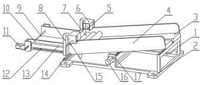
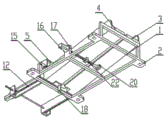
FIG. 1 is a schematic perspective view of the present invention;
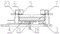
FIG. 2 is a schematic cross-sectional front view of the present invention;
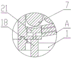
FIG. 3 is an enlarged view of point A of FIG. 2 according to the present invention;
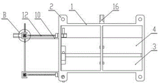
FIG. 4 is a schematic top view of the present invention;
FIG. 5 is a schematic diagram of the right-view structure of the present invention;
FIG. 6 is a schematic diagram of a right-side cross-sectional structure of the present invention;
FIG. 7 is a schematic bottom view of the present invention;
FIG. 8 is an enlarged view of point B of FIG. 7 according to the present invention;
fig. 9 is a schematic bottom perspective view of the present invention.
In the figure: 1. a frame; 2. a mounting seat; 3. a material feeding frame is fixed; 4. moving the feeding frame; 5. a material supporting plate; 6. taking a material frame; 7. a cylindrical blank; 8. moving the supporting block; 9. a drive shaft; 10. a transmission bracket; 11. a conveying motor; 12. a drive screw; 13. a sliding shaft; 14. a slide rail; 15. taking a material feeding cylinder; 16. a width adjustment motor; 17. a shaft lever supporting seat; 18. a material pushing cylinder; 19. a retractable plate; 20. a shaft lever connecting seat; 21. a material pushing plate; 22. a width adjustment threaded rod; 23. a cylinder fixing plate; 24. a shaft sleeve; 25. a gear; 26. external spiral threads.
Detailed Description
The technical solutions in the embodiments of the present invention will be clearly and completely described below with reference to the drawings in the embodiments of the present invention, and it is obvious that the described embodiments are only a part of the embodiments of the present invention, and not all of the embodiments. All other embodiments, which can be derived by a person skilled in the art from the embodiments given herein without making any creative effort, shall fall within the protection scope of the present invention.
Referring to fig. 1-9, the present invention provides a technical solution: an anti-falling automatic feeding device comprises a frame 1, a mounting seat 2, a fixed feeding frame 3, a movable feeding frame 4, a material supporting plate 5, a material taking frame 6, a cylindrical blank 7, a movable supporting block 8, a transmission shaft 9, a transmission bracket 10, a conveying motor 11, a transmission screw 12, a sliding shaft 13, a sliding rail 14, a material taking and placing cylinder 15, a width adjusting motor 16, a shaft lever supporting seat 17, a material pushing cylinder 18, a telescopic plate 19, a shaft lever connecting seat 20, a material pushing plate 21, a width adjusting threaded rod 22, a cylinder fixing plate 23, a shaft sleeve 24, a gear 25 and external spiral threads 26, wherein the mounting seat 2 is fixedly connected with two sides of the frame 1, the fixed feeding frame 3 is fixedly connected with the rear side of the upper end of the frame 1, the sliding rail 14 is arranged on the upper end faces of the left end and the right end of the frame 1, the movable feeding frame 4 is connected on the sliding rail 14, the telescopic plate 19 is fixedly connected with the side face of the front end of the fixed feeding, and the fixed feeding frame 3 and the movable feeding frame 4 are internally provided with cylindrical blanks 7, the fixed feeding frame 3 and the movable feeding frame 4 are fixedly connected with a shaft lever connecting seat 20 at the middle part of the bottom surface, the shaft lever connecting seat 20 is connected with a width adjusting threaded rod 22, the upper surface of the front end of the frame 1 is fixedly connected with a shaft lever supporting seat 17, the shaft lever supporting seat 17 is connected with a width adjusting motor 16, the shaft end of the width adjusting motor 16 is connected with one end of the width adjusting threaded rod 22, the left bottom surface of the movable feeding frame 4 is provided with a material pushing cylinder 18, the shaft end of the material pushing cylinder 18 is connected with a material pushing plate 21, the fixed feeding frame 3 and the lower part of the left end surface of the movable feeding frame 4 are fixedly connected with a transmission bracket 10, the transmission bracket 10 is connected with a sliding shaft 13, the lower end of the sliding shaft 13 is connected with a transmission screw 12, the transmission screw 12 and the, get the material frame 6 side and be provided with cylinder fixed plate 23, and be connected with on the cylinder fixed plate 23 and get blowing cylinder 15, and get blowing cylinder 15 axle head and be connected with and hold in the palm flitch 5, be connected with conveying motor 11 on the transmission support 10 left surface of moving feeding frame 4 one end, and conveying motor 11 axle head is connected with drive screw 12, drive screw 12 left end is provided with outer spiral line 26 on the surface, and is connected with transmission shaft 9 on the transmission support 10, be connected with gear 25 on the transmission shaft 9 both ends, and be provided with axle sleeve 24 on the transmission shaft 9 of the gear 25 left and right sides.
Decide axostylus axostyle connecting seat 20 and the width adjusting threaded rod 22 of 3 lower extremes of pan feeding frame and be connected through the bearing, and move axostylus axostyle connecting seat 20 and the width adjusting threaded rod 22 of pan feeding frame 4 lower extreme and be connected through the screw thread, can be convenient for rotate through width adjusting motor 16 and drive width adjusting threaded rod 22 and rotate, and can be convenient for drive through the screw thread on the width adjusting threaded rod 22 and move pan feeding frame 4 and slide around on slide rail 14 to can adjust the width of income material frame.
Get and be provided with square groove on the material frame 6 side, and hold in the palm flitch 5 through getting to be square groove on the material frame 6 side and get material frame 6 sliding connection, can be convenient for get 15 axle heads of blowing cylinder and drive and hold in the palm flitch 5 motion to make and hold in the palm flitch 5 slide in getting material frame 6, and can be convenient for get cylindrical stock 7 through the motion of holding in the palm flitch 5 and put.
Remove supporting shoe 8 and sliding shaft 13 sliding connection, and remove supporting shoe 8 and drive screw 12 and pass through threaded connection, can be convenient for rotate through conveying motor 11 and drive screw 12 and rotate, drive screw 12 passes through the screw drive and removes supporting shoe 8 and slide on sliding shaft 13 to can be convenient for remove the material loading to cylindrical stock 7.
Be provided with the shaft hole on axostylus axostyle supporting seat 17, and axostylus axostyle supporting seat 17 highly be higher than the bottom surface height of moving pan feeding frame 4, can be convenient for stretch out width adjustment motor 16's pivot to axostylus axostyle supporting seat 17 opposite side through the shaft hole on axostylus axostyle supporting seat 17, and can be convenient for carry on spacingly through axostylus axostyle supporting seat 17 to moving pan feeding frame 4 to prevent to move the pan feeding frame.
The material pushing cylinder 18 is fixedly connected to the bottom surface of the movable feeding frame 4, the cross section of the upper end surface of the material pushing plate 21 at the shaft end of the material pushing cylinder 18 is arc-shaped, the movable feeding frame 4 can be adjusted to drive the material pushing cylinder 18 to move simultaneously, so that the pushing force of the material pushing plate 21 on the cylindrical blank 7 is uniform, and the arc-shaped cross section of the upper end surface of the material pushing plate 21 can be attached to the surface of the cylindrical blank 7 conveniently, so that the material pushing plate 21 pushes the cylindrical blank 7 more stably.
The shaft sleeves 24 are symmetrically arranged on two sides of the gear 25, and the shaft sleeves 24 are movably connected with the transmission shaft 9 in a nested manner, so that the gear 25 can be always limited right above the external spiral threads 26 through the shaft sleeves 24, stable transmission is facilitated, and the shaft sleeves 24 can slide on the transmission shaft 9 when the width of the transmission support 10 is adjusted.
The gear 25 is arranged above the external spiral thread 26, the gear 25 is meshed with the external spiral thread 26, the external spiral thread 26 can be driven to rotate through the rotation of the transmission screw rod 12, the external spiral thread 26 drives the transmission shaft 9 to rotate through the gear 25, and therefore the transmission screw rod 12 at the rear end can be driven to rotate conveniently, and the two side-moving supporting blocks 8 can move left and right synchronously.
The working principle is as follows: firstly, an automatic feeding device is fixedly installed at a feeding port of a processing machine through installing seats 2 at two ends of a frame 1, transmission supports 10 at two ends are stretched into the processing machine, the width of the automatic feeding device is adjusted according to the length of a cylindrical blank 7, a width adjusting motor 16 is controlled to rotate, the width adjusting motor 16 rotates to drive a width adjusting threaded rod 22 to rotate, the width adjusting threaded rod 22 drives a movable feeding frame 4 to slide back and forth on a sliding rail 14 through a shaft rod connecting seat 20 at the lower end of the movable feeding frame 4 under the action of threads, and the width adjusting threaded rod can be adjusted to be matched with the width of the cylindrical blank 7;
when the movable feeding frame 4 is adjusted, the material pushing cylinder 18 at the lower end of the movable feeding frame 4 moves synchronously with the movable feeding frame 4, the material pushing plate 21 above the material pushing cylinder 18 is driven simultaneously, the transmission bracket 10 at the left end of the movable feeding frame 4 moves simultaneously under the driving of the movable feeding frame 4, and the gear 25 at the inner side of the transmission bracket 10 slides on the transmission shaft 9 under the pushing of the shaft sleeve 24;
after the automatic feeding device is adjusted, the cylindrical blank 7 is placed in the fixed feeding frame 3 and the movable feeding frame 4, the automatic feeding device is started, the material pushing cylinder 18 at the lower end of the movable feeding frame 4 pushes the material pushing plate 21 to move upwards, the material pushing plate 21 pushes the cylindrical blank 7 upwards and sends the cylindrical blank 7 into the material taking frames 6 at two ends, the material taking and placing cylinder 15 pushes the material supporting plate 5 to slide towards the interior of the material taking frame 6, the material pushing cylinder 18 drives the material pushing plate 21 to retract, and the material supporting plate 5 in the material taking frame 6 stably supports two ends of the cylindrical blank 7;
the conveying motor 11 rotates to drive the transmission screw 12 to rotate, the transmission screw 12 rotates to drive the movable supporting block 8 to slide leftwards on the sliding shaft 13, the outer spiral threads 26 rotate to drive the gear 25 to rotate, the transmission shaft 9 drives the transmission screw 12 at the rear end to rotate, the movable supporting block 8 at the rear end and the movable supporting block 8 at the front end synchronously move leftwards, when the movable supporting block 8 drives the material taking frame 6 to move to a specified material taking position, the material taking cylinder 15 drives the material supporting plate 5 to retract towards the recovery direction, so that the cylindrical blank 7 falls into a processing machine to be fixedly processed, and after the material taking action is completed, the material taking frame 6 returns to the original position to take materials next time.
It is to be understood that the terms "central," "longitudinal," "lateral," "front," "rear," "left," "right," "vertical," "horizontal," "top," "bottom," "inner," "outer," and the like are used in the orientations and positional relationships indicated in the drawings for the purpose of convenience and simplicity of description, and do not indicate or imply that the referenced devices or components must be in a particular orientation, constructed and operated in a particular orientation, and are not to be considered limiting of the scope of the present invention.
Although embodiments of the present invention have been shown and described, it will be appreciated by those skilled in the art that changes, modifications, substitutions and alterations can be made in these embodiments without departing from the principles and spirit of the invention, the scope of which is defined in the appended claims and their equivalents.
Claims (9)
1. The utility model provides an automatic loading attachment of anti falling, includes frame (1), its characterized in that: the automatic feeding device is characterized in that mounting seats (2) are fixedly connected to two sides of the frame (1), a fixed feeding frame (3) is fixedly connected to the rear side of the upper end of the frame (1), slide rails (14) are arranged on the upper end faces of the left end and the right end of the frame (1), a movable feeding frame (4) is connected to the slide rails (14), a telescopic plate (19) is fixedly connected to the side face of the front end of the fixed feeding frame (3), the telescopic plate (19) is connected with the movable feeding frame (4), cylindrical blanks (7) are arranged in the fixed feeding frame (3) and the movable feeding frame (4), a shaft lever connecting seat (20) is fixedly connected to the middle of the bottom face of the fixed feeding frame (3) and the movable feeding frame (4), a width adjusting threaded rod (22) is connected to the shaft lever connecting seat (20), a shaft lever supporting seat (17) is fixedly connected to the upper surface of the front end of the frame (1), and a width adjusting motor (, the end of a width adjusting motor (16) is connected with one end of a width adjusting threaded rod (22), a material pushing cylinder (18) is arranged on the bottom surface of the left side of the movable feeding frame (4), a material pushing plate (21) is connected with the end of the material pushing cylinder (18), a transmission bracket (10) is fixedly connected with the lower portion of the end surface of the left side of the fixed feeding frame (3) and the movable feeding frame (4), a sliding shaft (13) is connected onto the transmission bracket (10), a transmission screw (12) is connected with the lower end of the sliding shaft (13), a movable supporting block (8) is connected onto the transmission screw (12) and the sliding shaft (13), a material taking frame (6) is fixedly connected onto the movable supporting block (8), a cylinder fixing plate (23) is arranged on the side surface of the material taking frame (6), a material taking and placing cylinder (15) is connected onto the cylinder fixing plate (23), and a material supporting plate (, move and be connected with conveying motor (11) on transmission support (10) the left surface of material feeding frame (4) one end, and conveying motor (11) axle head is connected with drive screw (12), be provided with outer spiral line (26) on drive screw (12) left end surface, and be connected with transmission shaft (9) on transmission support (10), be connected with gear (25) on transmission shaft (9) both ends, and be provided with axle sleeve (24) on transmission shaft (9) of gear (25) left and right sides.
2. The automatic feeding device of claim 1, characterized in that: the shaft lever connecting seat (20) at the lower end of the fixed feeding frame (3) is connected with the width adjusting threaded rod (22) through a bearing, and the shaft lever connecting seat (20) at the lower end of the movable feeding frame (4) is connected with the width adjusting threaded rod (22) through threads.
3. The automatic feeding device of claim 1, characterized in that: the material taking frame is characterized in that a square groove is formed in the side face of the material taking frame (6), and the material supporting plate (5) is in sliding connection with the material taking frame (6) through the square groove in the side face of the material taking frame (6).
4. The automatic feeding device of claim 1, characterized in that: the movable supporting block (8) is in sliding connection with the sliding shaft (13), and the movable supporting block (8) is in threaded connection with the transmission screw rod (12).
5. The automatic feeding device of claim 1, characterized in that: the gear (25) at the rear end of the transmission shaft (9) is fixedly connected with the transmission shaft (9), the gear (25) at the front end of the transmission shaft (9) is in sliding connection with the transmission shaft (9), and two sides of the surface of the front end of the transmission shaft (9) are provided with symmetrical planes.
6. The automatic feeding device of claim 1, characterized in that: the shaft lever supporting seat (17) is provided with a shaft hole, and the height of the shaft lever supporting seat (17) is higher than the bottom surface height of the movable feeding frame (4).
7. The automatic feeding device of claim 1, characterized in that: the material pushing cylinder (18) is fixedly connected to the bottom surface of the movable material feeding frame (4), and the section of the upper end surface of a material pushing plate (21) at the shaft end of the material pushing cylinder (18) is arc-shaped.
8. The automatic feeding device of claim 1, characterized in that: the shaft sleeves (24) are symmetrically arranged on two sides of the gear (25), and the shaft sleeves (24) are movably connected with the transmission shaft (9) in a nested mode.
9. The automatic feeding device of claim 1, characterized in that: the gear (25) is arranged above the external spiral threads (26), and the gear (25) is meshed with the external spiral threads (26) and connected with each other.
Priority Applications (1)
| Application Number | Priority Date | Filing Date | Title |
|---|---|---|---|
| CN202011075341.7A CN112027584B (en) | 2020-10-10 | 2020-10-10 | Automatic loading attachment that anti-drop falls |
Applications Claiming Priority (1)
| Application Number | Priority Date | Filing Date | Title |
|---|---|---|---|
| CN202011075341.7A CN112027584B (en) | 2020-10-10 | 2020-10-10 | Automatic loading attachment that anti-drop falls |
Publications (2)
| Publication Number | Publication Date |
|---|---|
| CN112027584A true CN112027584A (en) | 2020-12-04 |
| CN112027584B CN112027584B (en) | 2022-02-01 |
Family
ID=73573399
Family Applications (1)
| Application Number | Title | Priority Date | Filing Date |
|---|---|---|---|
| CN202011075341.7A Active CN112027584B (en) | 2020-10-10 | 2020-10-10 | Automatic loading attachment that anti-drop falls |
Country Status (1)
| Country | Link |
|---|---|
| CN (1) | CN112027584B (en) |
Cited By (1)
| Publication number | Priority date | Publication date | Assignee | Title |
|---|---|---|---|---|
| CN113716299A (en) * | 2021-08-26 | 2021-11-30 | 万民鹏 | Cylindrical material arranging machine for rare earth metal neodymium iron boron production |
Citations (6)
| Publication number | Priority date | Publication date | Assignee | Title |
|---|---|---|---|---|
| US3809209A (en) * | 1971-05-18 | 1974-05-07 | Findus | Apparatus for controlling the feed of loose material |
| CN102397979A (en) * | 2011-12-08 | 2012-04-04 | 济南沃德汽车零部件有限公司 | Automatic loading device for horizontal electric upsetting machine |
| CN204124802U (en) * | 2014-09-15 | 2015-01-28 | 北京海普瑞森科技发展有限公司 | Automatic charging device |
| CN205237455U (en) * | 2015-12-30 | 2016-05-18 | 金石机器人常州股份有限公司 | Material loading way that axle type part was used |
| CN106516653A (en) * | 2016-11-17 | 2017-03-22 | 刘子琪 | Feeding mechanism of short cylindrical material |
| CN210682358U (en) * | 2019-10-15 | 2020-06-05 | 东莞市三姆森光电科技有限公司 | Stack type cartridge clip feeding mechanism |
-
2020
- 2020-10-10 CN CN202011075341.7A patent/CN112027584B/en active Active
Patent Citations (6)
| Publication number | Priority date | Publication date | Assignee | Title |
|---|---|---|---|---|
| US3809209A (en) * | 1971-05-18 | 1974-05-07 | Findus | Apparatus for controlling the feed of loose material |
| CN102397979A (en) * | 2011-12-08 | 2012-04-04 | 济南沃德汽车零部件有限公司 | Automatic loading device for horizontal electric upsetting machine |
| CN204124802U (en) * | 2014-09-15 | 2015-01-28 | 北京海普瑞森科技发展有限公司 | Automatic charging device |
| CN205237455U (en) * | 2015-12-30 | 2016-05-18 | 金石机器人常州股份有限公司 | Material loading way that axle type part was used |
| CN106516653A (en) * | 2016-11-17 | 2017-03-22 | 刘子琪 | Feeding mechanism of short cylindrical material |
| CN210682358U (en) * | 2019-10-15 | 2020-06-05 | 东莞市三姆森光电科技有限公司 | Stack type cartridge clip feeding mechanism |
Cited By (1)
| Publication number | Priority date | Publication date | Assignee | Title |
|---|---|---|---|---|
| CN113716299A (en) * | 2021-08-26 | 2021-11-30 | 万民鹏 | Cylindrical material arranging machine for rare earth metal neodymium iron boron production |
Also Published As
| Publication number | Publication date |
|---|---|
| CN112027584B (en) | 2022-02-01 |
Similar Documents
| Publication | Publication Date | Title |
|---|---|---|
| CN112027584B (en) | Automatic loading attachment that anti-drop falls | |
| CN110802274B (en) | Continuous cutting device for plates | |
| CN111188480B (en) | Automatic wall plastering robot | |
| CN116442356A (en) | Ceramic roll forming machine | |
| CN112320222B (en) | Telescopic control mechanism for conveying device | |
| CN209222880U (en) | A kind of Aluminum Cutting machine positioning device | |
| CN109647999B (en) | Automatic material forming and conveying device in stamping process of engine support | |
| CN212502791U (en) | Foundation cover transfer station | |
| CN219028423U (en) | Automatic traction device for PE pipe production | |
| CN112743974A (en) | Multi-station upward-swinging heat transfer printing machine for taper products | |
| CN113523048B (en) | U-shaped bolt fastener cold bending forming device | |
| CN219094007U (en) | Laser pipe cutting device | |
| CN220640551U (en) | Structure of case sealer | |
| CN220763519U (en) | Linear automatic cutting equipment for plastic bottles | |
| CN115069511B (en) | Cable sleeve surface anti-corrosion treatment device for track traffic | |
| CN219823116U (en) | Cloth feeding device | |
| CN215658901U (en) | Automatic screw locking machine based on machine vision | |
| CN215556519U (en) | Telescopic conveying mechanism for automobile part production | |
| CN220464154U (en) | Automatic layering cutting device of sponge | |
| CN212712024U (en) | Traction equipment is used in production of special fluorine dragon conveyer belt | |
| CN218778182U (en) | Speed-adjustable feeding device | |
| CN219076807U (en) | Printing laminating machine for bag making | |
| CN218836319U (en) | Cutting machine convenient to adjust | |
| CN213195075U (en) | Mandrel drawing machine conveying device with good stability | |
| CN211169118U (en) | Plastic film conveying device |
Legal Events
| Date | Code | Title | Description |
|---|---|---|---|
| PB01 | Publication | ||
| PB01 | Publication | ||
| SE01 | Entry into force of request for substantive examination | ||
| SE01 | Entry into force of request for substantive examination | ||
| GR01 | Patent grant | ||
| GR01 | Patent grant |