Disclosure of Invention
In order to solve the technical problem, the multifunctional automatic blade machining equipment can be used for machining the blade in a full-automatic mode, and the functions of positioning, fixing and releasing the blade are fast and efficient.
In order to achieve the above purposes, the technical scheme adopted by the invention is as follows:
the utility model provides a multi-functional blade automatic processing equipment, is applied to and processes out straight flute and chute on the rectangle blade, includes: a frame; the indexing disc is arranged on the rack, the output end of the indexing disc is provided with four stations, and the four stations are uniformly distributed around the driving axis of the indexing disc; the four clamps are respectively arranged on each station of the index plate; the driving mechanism is used for driving the clamp to open and close so as to clamp or release the blade; the feeding device is arranged on the frame, is arranged beside the first station of the index plate and is used for placing a blade to be machined on the tool clamp; the straight groove processing device is arranged on the rack, is arranged beside the second station of the dividing plate and is used for processing a straight groove of the blade; the chute processing device is arranged on the rack, is arranged beside the third station of the dividing plate and is used for processing a chute of the blade; the discharging device is arranged on the rack, and the discharging device 7 is arranged beside the fourth station of the index plate and used for taking out the machined blade from the tool clamp; the jig includes: the blade sliding groove is used for placing a blade, and the width of the blade sliding groove is the same as that of the blade; the blade clamping block is arranged right above one end of the blade sliding groove, and the length of the blade sliding groove is greater than the sum of the lengths of the blade and the blade clamping block; the blade push block is arranged in the blade sliding groove in a sliding mode and provided with two output ends, the first output end and the second output end of the blade push block are located on two sides of the blade respectively, and the distance between the first output end and the second output end of the blade push block is larger than the length of the blade.
Preferably, the blade runner includes: the bottom wall is horizontally arranged at the output end of the dividing plate and is in a rectangular flat plate shape; the two side walls are vertical plates vertically extending upwards along the two long edges of the bottom wall, and a round angle facilitating the sliding of the blade is arranged on one side, close to the bottom wall, of the top end of each side wall; the blade pushing block is arranged on one side far away from the stopping wall.
Preferably, the cartridge comprises: the clamp plate, the clamp plate sets up directly over the diapire and be close to the position of locking wall, clamp plate and lateral wall fixed connection, the bottom surface of clamp plate is the inclined plane, the clamp plate is close to the thickness that the distance between its bottom surface of one end of locking wall and the diapire is less than the blade, the clamp plate is kept away from the distance between its bottom surface of one end of locking wall and the diapire and is greater than the thickness of blade, the clamp plate is elastic material.
Preferably, the blade pusher includes:
the first sliding block is connected with the bottom wall in a sliding manner; the second sliding block penetrates through the stop wall and is in sliding connection with the stop wall; and the connecting rod is used for fixedly connecting the first sliding block and the second sliding block.
Preferably, the one end that the second slider is close to the diapire is provided with the push pedal with diapire top surface clearance fit, is provided with the holding tank that is used for holding the push pedal on the retaining wall.
Preferably, be provided with the vertical blanking hole that runs through the diapire on the diapire, the width in blanking hole is less than the width of diapire, and the blanking hole is located the below of locking wall, installs the funnel below the blanking hole with embedded, and the below of funnel is provided with the waste material box of placing in graduated disk non-working portion.
Preferably, a top end of the first slider is provided with a projection protruding upward, and the driving mechanism includes: the number of the elastic pieces is four, the elastic pieces are sleeved on each second sliding block, and the elastic pieces enable the second sliding blocks to always have the tendency of moving towards the direction far away from the bottom wall; the two first linear drivers are arranged on the rack, the two first linear drivers are respectively positioned beside the first station and the fourth station, and the output ends of the first linear drivers horizontally face the bumps; the concave blocks are the same in number as the first linear drivers and correspond to the first linear drivers one by one, the concave blocks are fixedly mounted at the output ends of the first linear drivers, the concave blocks are buckled on the convex blocks, and the concave blocks are provided with avoiding openings used for avoiding the convex blocks to move along with the output ends of the dividing plates.
Preferably, the feeding device comprises: the output end of the second linear driver is horizontally arranged towards the dividing plate; the third linear driver is arranged at the output end of the second linear driver, and the output end of the third linear driver is vertically arranged downwards; the three-way valve is arranged at the output end of the third linear driver and is provided with three ventilation ends, and the first ventilation end of the three-way valve is communicated with the atmosphere; the sucker is arranged at the output end of the third linear driver, the air inlet end of the sucker is vertically arranged downwards, and the air outlet end of the sucker is communicated with the second ventilation end of the three-way valve; and the input end of the vacuum pump is communicated with the third gas end of the three-way valve.
Preferably, the straight flute processing device includes:
the fourth linear driver is arranged on the rack, and the output end of the fourth linear driver is horizontally arranged; the fifth linear driver is arranged at the output end of the fourth linear driver, and the output end of the fifth linear driver is vertically arranged; the rotary driver is arranged at the output end of the fifth linear driver, and the output end of the rotary driver is vertically arranged downwards; and the milling cutter is coaxially arranged at the output end of the rotary driver.
Compared with the prior art, the invention has the beneficial effects that:
the invention realizes the functions of positioning, fixing and releasing the blade with high efficiency through the clamp and the driving mechanism, and the specific method comprises the following steps: the convex block moves along with the output end of the dividing disc in a circumferential mode, the convex block passes through the avoidance opening and moves into the concave block, the concave block is driven by the first linear driver to shrink, the concave block drags the first sliding block to move towards the direction far away from the stop wall, and a space for the blade to be vertically and downwardly placed is reserved between the first sliding block and the second sliding block; the feeding device is used for placing the blade on the bottom wall from top to bottom, the short edge of the blade slides into the space between the two side walls along the guidance of a fillet, and the long edge of the blade is positioned between the first sliding block and the second sliding block; the first linear driver resets, the first sliding block drives the blade to approach the stop wall under the action of the resilience force of the elastic piece, the blade is extruded into the bottom of the pressing plate until the blade is abutted against the stop wall, at the moment, the top surface of the blade is pressed by the resilience force of the pressing plate, and meanwhile, the second sliding block is retracted into the stop wall; when the blade is released, the concave block is driven to shrink again by the first linear driver, and the first sliding block drives the second sliding block to push the blade out of the lower part of the pressing plate.
Detailed Description
The following description is presented to disclose the invention so as to enable any person skilled in the art to practice the invention. The preferred embodiments in the following description are given by way of example only, and other obvious variations will occur to those skilled in the art.
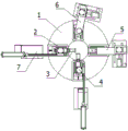
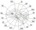
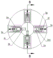
An automatic multifunctional blade processing device is applied to processing a straight groove and a skewed groove on a rectangular blade, as shown in figures 1, 2 and 3, and comprises: a frame; the indexing disc 1 is arranged on the frame, the output end of the indexing disc 1 is provided with four stations, and the four stations are uniformly distributed around the driving axis of the indexing disc 1; the four clamps 2 are respectively arranged on each station of the index plate 1; the driving mechanism 3 is used for driving the clamp 2 to open and close so as to clamp or release the blade; the feeding device 4 is arranged on the rack, and the feeding device 4 is arranged beside the first station of the index plate 1 and used for placing a blade to be machined on the tool clamp; the straight groove processing device 5 is arranged on the rack, and the straight groove processing device 5 is arranged beside the second station of the dividing plate 1 and used for processing a straight groove of the blade; the chute processing device 6 is arranged on the rack, and the chute processing device 6 is arranged beside the third station of the dividing plate 1 and used for processing a chute of the blade; and the discharging device 7 is arranged on the rack, and the discharging device 7 is arranged beside the fourth station of the index plate 1 and used for taking out the machined blade from the tool clamp.
As shown in fig. 10, 11 and 12, the jig 2 includes: the blade sliding groove is used for placing a blade, and the width of the blade sliding groove is the same as that of the blade; the blade clamping block is arranged right above one end of the blade sliding groove, and the length of the blade sliding groove is greater than the sum of the lengths of the blade and the blade clamping block; the blade push block is arranged in the blade sliding groove in a sliding mode and provided with two output ends, the first output end and the second output end of the blade push block are located on two sides of the blade respectively, and the distance between the first output end and the second output end of the blade push block is larger than the length of the blade.
The working principle of the invention is as follows:
the driving mechanism 3 drives the blade pushing block on the first station to move towards the direction far away from the blade clamping block, and the feeding device 4 places the blade to be processed in the blade sliding groove from top to bottom; the first output end of the blade push block pushes the blade to enter the blade clamping block along the blade sliding groove under the driving of the driving mechanism 3, the upper surface and the lower surface of the blade are clamped by the top surface of the blade sliding groove and the bottom surface of the blade clamping block, the left surface and the right surface of the blade are propped against by the inner wall of the blade sliding groove, and the front surface and the rear surface of the blade are clamped by the blade clamping block and the blade push block; the dividing plate 1 drives the clamp 2 to sequentially move to the working ends of the straight groove machining device 5, the chute machining device 6 and the discharging device 7, the straight groove machining device 5 machines a straight groove on the blade, and the chute machining device 6 machines a chute on the blade; the driving mechanism 3 drives the blade pushing block on the first station to move towards the direction far away from the blade clamping block again, the second output end of the blade pushing block pushes the blade to be separated from the blade clamping block along the blade sliding groove under the driving of the driving mechanism 3, and the discharging device 7 takes out the blade on the blade sliding groove from bottom to top.
As shown in fig. 8 and 9, the blade slide groove includes: the bottom wall 2a is horizontally arranged at the output end of the index plate 1, and the bottom wall 2a is in a rectangular flat plate shape; two side walls 2b, the side walls 2b are vertical plates extending vertically upwards along two long edges of the bottom wall 2a, and a round corner 2b1 convenient for the blade to slide in is arranged at one side of the top end of the side wall 2b close to the bottom wall 2 a; and a stopper wall 2c having a vertical plate shape extending vertically upward along one short side of the bottom wall 2a, a blade catching block being provided on a side close to the stopper wall 2c, and a blade pushing block being provided on a side away from the stopper wall 2 c.
The working principle of the blade sliding groove is as follows: the feeding device 4 puts the blade on the bottom wall 2a from top to bottom, two sides of the blade slide into the space between the two side walls 2b along the guide of the fillet 2b1, and when the blade is clamped, the blade push block pushes the blade to be close to the stop wall 2c, so that the blade is tightly pressed against the stop wall 2c and is simultaneously pressed by the blade clamping block.
As shown in fig. 9 and 12, the cartridge includes: the pressing plate 2d is arranged right above the bottom wall 2a and close to the position of the stop wall 2c, the pressing plate 2d is fixedly connected with the side wall 2b, the bottom surface of the pressing plate 2d is an inclined surface, the distance between the bottom surface of one end, close to the stop wall 2c, of the pressing plate 2d and the bottom wall 2a is smaller than the thickness of the blade, the distance between the bottom surface of one end, far away from the stop wall 2c, of the pressing plate 2d and the bottom wall 2a is larger than the thickness of the blade, and the pressing plate 2d is made of elastic materials.
The working principle of the blade clamping block is as follows: the blade ejector pad pushes the blade to extrude into the bottom of the pressing plate 2d, the closer the blade is to the stop wall 2c, the smaller the distance between the blade and the pressing plate 2d is, after the blade is tightly supported by the pressing plate 2d, the blade overcomes the resilience force of the pressing plate 2d to continuously advance until the blade is tightly supported by the stop wall 2c, and at the moment, the top surface of the blade is tightly pressed by the resilience force of the pressing plate 2 d.
As shown in fig. 9 and 12, the blade pusher includes: the first sliding block 2e is connected with the bottom wall 2a in a sliding mode; a second slider 2f, the second slider 2f penetrating the stop wall 2c and being slidably connected to the stop wall 2 c; and the connecting rod 2g is used for fixedly connecting the first slide block 2e and the second slide block 2 f.
The working principle of the blade push block is as follows:
the bottom wall 2a is in a square shape, a sliding rail in sliding fit with the first sliding block 2e is arranged on the bottom wall 2a, the second sliding block 2f is in a guide pillar shape, a guide sleeve in sliding fit with the second sliding block 2f is arranged on the stop wall 2c, and the first sliding block 2e and the second sliding block 2f are linked through a connecting rod 2 g; when the first slider 2e moves towards the direction approaching the stop wall 2c, the second slider 2f gradually slides towards the direction away from the bottom wall 2a, and when the first slider 2e pushes the blade to abut against the stop wall 2c, the second slider 2f is completely submerged inside the stop wall 2 c; when the first slider 2e moves in a direction away from the stopper wall 2c, the second slider 2f gradually slides in a direction close to the bottom wall 2a, and when the first slider 2e moves to the initial position, the second slider 2f completely pushes the blade out of the working range of the pressing plate 2 d.
As shown in fig. 9 and 12, one end of the second slider 2f close to the bottom wall 2a is provided with a push plate 2f1 which is in clearance fit with the top surface of the bottom wall 2a, and the stop wall 2c is provided with a receiving groove 2c1 for receiving the push plate 2f 1. Working principle of the push plate 2f1 and the receiving groove 2c 1: the push plate 2f1 is used to push the blade, so that the second slide block 2f can push the blade with any thickness, and when the second slide block 2f is completely submerged in the stop wall 2c, the push plate 2f1 is located in the accommodating groove 2c1, and the second slide block 2f is prevented from interfering with the blade and the stop wall 2 c.
As shown in fig. 9 and 12, the bottom wall 2a is provided with a blanking hole 2a1 vertically penetrating through the bottom wall 2a, the width of the blanking hole 2a1 is smaller than that of the bottom wall 2a, the blanking hole 2a1 is located below the stop wall 2c, a funnel 2a2 is embedded below the blanking hole 2a1, and a waste box 2a3 placed in the non-working part of the index plate 1 is arranged below the funnel 2a 2. The principle of operation of the blanking hole 2a1, the funnel 2a2 and the waste box 2a3 is as follows: the chips generated during the blade machining fall through the blanking hole 2a1, and the chips are centrally gathered under the guidance of the hopper 2a2 and then fall into the interior of the scrap box 2a3 for temporary storage.
As shown in fig. 9 and 12, the top end of the first slider 2e is provided with a projection 2e1 protruding upward, and the driving mechanism 3 includes: the number of the elastic pieces 3a is four, the elastic pieces 3a are sleeved on each second sliding block 2f, and the elastic pieces 3a enable the second sliding blocks 2f to always have the tendency of moving towards the direction far away from the bottom wall 2 a; the two first linear drivers 3b are arranged on the rack, the two first linear drivers 3b are respectively positioned at the sides of the first station and the fourth station, and the output ends of the first linear drivers 3b horizontally face the bumps 2e 1; the number of the concave blocks 3c is the same as that of the first linear drivers 3b, the concave blocks 3c correspond to the first linear drivers 3b one by one, the concave blocks 3c are fixedly installed at the output ends of the first linear drivers 3b, the concave blocks 3c are buckled on the convex blocks 2e1, and the concave blocks 3c are provided with avoidance openings 3c1 for avoiding the convex blocks 2e1 to move along with the output ends of the indexing disc 1.
The specific working principle of the driving mechanism 3 is as follows:
the elastic piece 3a is a spring, two ends of the elastic piece 3a are respectively abutted against the stop wall 2c and the connecting rod 2g, the second sliding block 2f always has a trend of being far away from the bottom wall 2a under the drive of the resilience force of the elastic piece 3a, and the first sliding block 2e moves together with the first sliding block 2e through the connecting rod 2g, so that the first sliding block 2e always has a trend of being close to the stop wall 2c, and the first sliding block 2e always clamps the blade together with the stop wall 2c under the action of no external force; the first linear driver 3b is an air cylinder, the initial state of the first linear driver 3b is an extended state, when the clamp 2 moves to the side of the feeding device 4 and the discharging device 7, the lug 2e1 moves along with the output end of the dividing disc 1 in a circle, the lug 2e1 moves to the inside of the concave block 3c through the avoidance opening 3c1, the concave block 3c is driven by the first linear driver 3b to contract, and the concave block 3c drags the first slide block 2e to move towards the direction far away from the stop wall 2c, so that the feeding device 4 can be placed in or the discharging device 7 can be moved out of the blade.
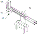
As shown in fig. 4, the feeding device 4 includes: a second linear driver 4a, wherein the output end of the second linear driver 4a is horizontally arranged towards the dividing plate 1; the third linear driver 4b is arranged at the output end of the second linear driver 4a, and the output end of the third linear driver 4b is vertically arranged downwards; the three-way valve 4c is arranged at the output end of the third linear driver 4b, the three-way valve 4c is provided with three ventilation ends, and a first ventilation end of the three-way valve 4c is communicated with the atmosphere; the sucker 4d is arranged at the output end of the third linear driver 4b, the air inlet end of the sucker 4d is vertically arranged downwards, and the air outlet end of the sucker 4d is communicated with the second air vent end of the three-way valve 4 c; and a vacuum pump (not shown), an input end of which is communicated with a third ventilation end of the three-way valve 4 c.
The working principle of the feeding device 4 is as follows:
the second linear actuator 4a and the third linear actuator 4b are both air cylinders; when the blade is sucked by the feeding device 4, the three-way valve 4c is communicated with the vacuum pump and the sucker 4d, and after the air inlet end of the sucker 4d is attached to the blade, the vacuum pump works to enable the inner part of the sucker 4d to generate vacuum, so that the sucker 4d can suck the blade tightly; when the blade is released by the feeding device 4, the vacuum pump is closed, the three-way valve 4c is communicated with the atmosphere and the sucking disc 4d, and air enters the sucking disc 4d to make the inside of the sucking disc 4d lose vacuum, so that the sucking disc 4d can release the blade; the feeding device 4 feeds by means of a vibrating feeder, of which only the end rail is shown as a schematic representation.
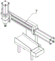
As shown in fig. 5, the loading device 4 and the unloading device 7 have the same structure and the same working principle, and the unloading device 7 places the blade into the chute, along which the blade slides into the finished box.
As shown in fig. 6, the straight groove processing apparatus 5 includes:
the fourth linear driver 5a is arranged on the rack, and the output end of the fourth linear driver 5a is horizontally arranged; the fifth linear driver 5b is arranged at the output end of the fourth linear driver 5a, and the output end of the fifth linear driver 5b is vertically arranged; the rotary driver 5c is arranged at the output end of the fifth linear driver 5b, and the output end of the rotary driver 5c is vertically arranged downwards; and a milling cutter 5d coaxially mounted at the output end of the rotary driver 5 c. The working principle of the straight groove processing device 5 is as follows: the fourth linear driver 5a and the fifth linear driver 5b are both electric push rods, the rotary driver 5c is a servo motor provided with a speed reducer, the rotary driver 5c is used for driving the milling cutter 5d to rotate at a high speed so that the milling cutter has the function of milling a long groove, the fifth linear driver 5b is used for driving the milling cutter 5d to vertically and downwards approach the blade, and the fourth linear driver 5a is used for driving the milling cutter 5d to move along the grooving direction.
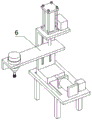
As shown in fig. 7, the straight flute processing device 5 and the inclined flute processing device 6 have the same structure, the straight flute processing device 5 and the inclined flute processing device 6 have the same operation principle, and the straight flute processing device 5 and the inclined flute processing device 6 are different in the traveling direction of the milling cutter.
The foregoing shows and describes the general principles, essential features, and advantages of the invention. It will be understood by those skilled in the art that the present invention is not limited to the embodiments described above, which are merely illustrative of the principles of the invention, but that various changes and modifications may be made without departing from the spirit and scope of the invention, which fall within the scope of the invention as claimed. The scope of the invention is defined by the appended claims and equivalents thereof.