CN111945629A - Double-resistance type highway protection buffer device - Google Patents
Double-resistance type highway protection buffer device Download PDFInfo
- Publication number
- CN111945629A CN111945629A CN202010840106.8A CN202010840106A CN111945629A CN 111945629 A CN111945629 A CN 111945629A CN 202010840106 A CN202010840106 A CN 202010840106A CN 111945629 A CN111945629 A CN 111945629A
- Authority
- CN
- China
- Prior art keywords
- sliding sleeve
- guardrail
- upright post
- spring
- highway
- Prior art date
- Legal status (The legal status is an assumption and is not a legal conclusion. Google has not performed a legal analysis and makes no representation as to the accuracy of the status listed.)
- Pending
Links
Images


Classifications
-
- E—FIXED CONSTRUCTIONS
- E01—CONSTRUCTION OF ROADS, RAILWAYS, OR BRIDGES
- E01F—ADDITIONAL WORK, SUCH AS EQUIPPING ROADS OR THE CONSTRUCTION OF PLATFORMS, HELICOPTER LANDING STAGES, SIGNS, SNOW FENCES, OR THE LIKE
- E01F15/00—Safety arrangements for slowing, redirecting or stopping errant vehicles, e.g. guard posts or bollards; Arrangements for reducing damage to roadside structures due to vehicular impact
- E01F15/02—Continuous barriers extending along roads or between traffic lanes
- E01F15/04—Continuous barriers extending along roads or between traffic lanes essentially made of longitudinal beams or rigid strips supported above ground at spaced points
- E01F15/0407—Metal rails
- E01F15/0438—Spacers between rails and posts, e.g. energy-absorbing means
-
- E—FIXED CONSTRUCTIONS
- E01—CONSTRUCTION OF ROADS, RAILWAYS, OR BRIDGES
- E01F—ADDITIONAL WORK, SUCH AS EQUIPPING ROADS OR THE CONSTRUCTION OF PLATFORMS, HELICOPTER LANDING STAGES, SIGNS, SNOW FENCES, OR THE LIKE
- E01F15/00—Safety arrangements for slowing, redirecting or stopping errant vehicles, e.g. guard posts or bollards; Arrangements for reducing damage to roadside structures due to vehicular impact
- E01F15/02—Continuous barriers extending along roads or between traffic lanes
- E01F15/04—Continuous barriers extending along roads or between traffic lanes essentially made of longitudinal beams or rigid strips supported above ground at spaced points
- E01F15/0461—Supports, e.g. posts
Abstract
The invention discloses a double-resistance type highway protection buffer device which comprises an upright post, a connecting arm, a sliding sleeve, a spring and a guardrail, wherein the sliding sleeve comprises a first sliding sleeve and a second sliding sleeve; the upright posts are vertically arranged in the middle of an isolation belt of the highway or on two sides of the highway; the vertical column is sequentially provided with a snap ring, a first sliding sleeve, a second sliding sleeve and a blocking piece from bottom to top, wherein the snap ring and the blocking piece are fixedly connected with the vertical column, and the first sliding sleeve and the second sliding sleeve can be connected in a relatively sliding manner along the axial direction of the vertical column; a spring is arranged between the clamping ring and the first sliding sleeve, and two ends of the spring are connected with the clamping ring and the first sliding sleeve; a spring is arranged between the second sliding sleeve and the blocking piece, and two ends of the spring are connected with the second sliding sleeve and the blocking piece; the device has increased the buffer distance of vehicle when striking the guardrail through structural design, and the shrink of guardrail drives subtend guardrail and draws close to the middle part, through the superpose of two-layer guardrail, has increased fracture resistance intensity, has very big positive effect to reducing accident level.
Description
Technical Field
The invention relates to the field of highway guardrail energy absorption structures, in particular to a double-resistance type highway protection buffer device.
Background
An expressway, referred to as a highway for short, is a highway dedicated for high-speed driving of automobiles. Highways have different regulations in different countries, times and scientific research and academic fields. According to the Chinese road engineering technology Standard (JTG B01-2014): the highway is a multi-lane highway which is specially used for cars to drive in different directions and lanes and completely control the entrance and exit. The annual average daily designed traffic volume of the highway is preferably more than 15000 passenger cars, and the designed speed is 80-120 kilometers per hour. By 12 and 28 months in 2018, the total mileage of the expressway in China reaches 14 ten thousand kilometers, and the expressway occupies the first place in the world.
The guardrail is a facility mainly used for protecting and protecting personal safety and equipment facilities in occasions such as houses, roads, commercial districts, public places and the like.
On the highway, as the vehicle speed is higher, once a traffic accident occurs, the consequence is very serious, and the traffic accident generally belongs to a great and extra-large traffic accident; therefore, a highway guard rail (called highway guard rail for short) is required to be arranged on the middle isolation belt and the roadside of the highway without break points.
The highway guardrail is different from guardrails used in other places, the guardrail used in other places is not easy to deform and shake due to the fact that the strength is considered preferentially, and is a main factor to be considered mainly from the safety perspective, while the highway guardrail is not too high in strength due to the fact that the energy absorption (buffering) effect is considered preferentially, so that the highway guardrail generally seen by people is a semi-steel guardrail and is a continuous structure formed by splicing corrugated steel guardrail plates and supporting the corrugated steel guardrail plates by main columns. The vehicle can absorb energy when colliding, is not easy to be collided, and can well protect the vehicle and the driver and passengers.
The deformation distance which can be generated when the conventional highway guardrail is impacted is very limited, only the corrugated steel guardrail plate has energy absorption capacity, and other structures (such as upright posts) need to keep the characteristic strength, so that the danger that a vehicle is not flushed out (or flushed to an opposite lane) when the vehicle impacts the highway guardrail can be avoided; the other problem is caused, because the energy absorption distance is short, when a vehicle collides with the guardrail, the speed is reduced from zero to the maximum (namely, the vehicle stops) under the condition of extremely short distance, so that the vehicle is seriously deformed after the collision, most of the conditions can cause vehicle damage and people death, and once the accident occurs on the expressway, the accident is generally the cause of major or extra major accidents, and the reason is that the effective energy absorption distance is short, the braking distance is short after the vehicle collides, and the caused consequence is very serious.
Secondly, the speed of the vehicles on the highway is 100-120KM/h, the mass of the vehicles is greatly different, for example, the vehicles are large and heavy, the inertia is large, once the vehicles collide with the guardrails, particularly the guardrails of the isolation belts in the middle, the vehicles on the opposite lanes are easy to collide with the opposite lanes, the vehicles on the opposite lanes run at high speed, once the vehicles collide with the opposite lanes, the consequences are very serious, and the caused accidents are interlinked accidents; saw statistics shows that 238351 (only reported) road traffic accidents occur in 2019 all the year around the country, 67759 people die, 275125 people are injured, and 9.1 million yuan of direct property loss is caused.
Therefore, a highway guardrail structure with long buffer distance and high strength is developed to reduce traffic accidents on a highway as much as possible, increase the buffer distance and reduce the damage of the guardrail to drivers; meanwhile, under the condition of ensuring the above conditions, the strength of the guard rail is further enhanced, and the serious traffic accident caused by breaking the guard rail is avoided as much as possible.
Disclosure of Invention
The invention aims to provide a double-resistance type highway protection buffer device, which greatly increases the buffer distance of a vehicle when the vehicle impacts a guardrail through the structural design, and when the vehicle collides at one side, the guardrail contracts to drive opposite guardrails to approach to the middle part, and the strength of the opposite guardrails is enhanced through the superposition of two layers of guardrails, so that the energy absorption is ensured, the fracture resistance strength is also increased, the effect is very obvious, and the double-resistance type highway protection buffer device has a great positive effect on reducing the accident grade.
A double-resistance type highway protection buffer device comprises an upright post, a connecting arm, a sliding sleeve, a spring and a guardrail, wherein the sliding sleeve comprises a first sliding sleeve and a second sliding sleeve; the method is characterized in that:
the upright posts are vertically arranged in the middle of an isolation belt of the highway or on two sides of the highway;
the upright post is sequentially provided with a snap ring, a first sliding sleeve, a second sliding sleeve and a baffle piece from bottom to top, wherein the snap ring and the baffle piece are fixedly connected with the upright post, and the first sliding sleeve and the second sliding sleeve can be connected in a relatively sliding manner along the axial direction of the upright post; a spring is arranged between the clamping ring and the first sliding sleeve, and two ends of the spring are connected with the clamping ring and the first sliding sleeve; a spring is arranged between the second sliding sleeve and the blocking piece, and two ends of the spring are connected with the second sliding sleeve and the blocking piece;
the single side wall or the double side walls of the first sliding sleeve and the second sliding sleeve are hinged with one end of a connecting arm, and the connecting arm can swing up and down; the other end of the connecting arm is hinged with the guardrail, wherein the connecting arm, the guardrail and the upright post form a trapezoidal structure together;
the guardrail is of a wave-shaped structure, a reinforcing plate is arranged on the inner side of the guardrail along the axial direction of the guardrail, and the connecting arm is hinged with the reinforcing plate;
the distance between the upright posts is 1-5 m.
Preferably, the upright post, the first sliding sleeve, the second sliding sleeve and the connecting arm are made of steel structures.
Furthermore, the upright post, the first sliding sleeve and the second sliding sleeve are externally provided with antirust coatings or paint spraying.
Preferably, when the upright post is positioned in the middle isolation zone of the highway, connecting arms are hinged to the two sides of the first sliding sleeve and the second sliding sleeve; when the stand is located highway both sides side, first sliding sleeve, second sliding sleeve unilateral hinge have the linking arm.
Preferably, the bottom of the upright post is fixed and provided with triangular forked support legs, so that the upright post is not easy to bend when being impacted.
The invention has the following beneficial effects:
the first technical scheme of the invention has double buffering effects after the vehicle is impacted, the first one is a wavy guardrail and has buffering effects, namely the buffering mode commonly used at present, the second one is the matching of the connecting arm and the spring, after the guardrail is impacted, the spring can be compressed, the guardrail can move towards the upright post to realize buffering, and compared with the first buffer, the buffering stroke of the buffering is long, so that the buffering has great improvement on the safety protection of passengers, and due to the buffering, the strength of the guardrail can be improved, and the buffering effect is great improvement on the highway isolation belt.
Secondly, all structural parts are parallel to the vehicle after being impacted under the condition of ensuring the maximum buffer degree, and the structural parts vertical to the vehicle are avoided by technical means; if the structural member is perpendicular to the vehicle, the structural member can be inserted into the vehicle like a sword in the collision process, and serious threats are caused to people in the vehicle.
Third, in this application, at the guardrail at median middle part, when the vehicle striking guardrail, the contralateral guardrail also can draw close towards the middle part, forms the secondary guarantee in proper order, is equivalent to the structure of two-layer guardrail superpose, and the guardrail of its constitution, intensity is two times original, and solves the problem that the striking breaks the guardrail and lasts to the opposite direction lane from this technical means aspect.
Fourth, this application has only reached above-mentioned technological effect simultaneously through above-mentioned simple structure, and this is that prior art can't reach, and this application structure, implementation cost is lower relatively, installs simple, convenient moreover, changes also conveniently, and structural integrity is strong.
Drawings
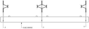
Fig. 1 is a schematic view of the overall structure of the present invention.
FIG. 2 is a schematic side view of the present invention.
Fig. 3 is a schematic view of the installation of the baffle plate and the upright post of the invention.
Fig. 4 is a side view installation schematic of the present invention.
Fig. 5 is a top view installation schematic of the present invention.
Fig. 6 is a schematic view of the impact principle of the present invention.
Fig. 7 is a schematic representation of the post-impact effect of the present invention.
In the figure, an upright post 1, a clamping ring 1-1, a baffle plate 1-2, a connecting arm 2, a first sliding sleeve 3, a second sliding sleeve 4, a spring 5, a guardrail 6 and a reinforcing plate 6-1.
Detailed Description
The technical solutions in the embodiments of the present invention will be clearly and completely described below with reference to the drawings in the embodiments of the present invention, and it is obvious that the described embodiments are only a part of the embodiments of the present invention, and not all of the embodiments.
In the description of the present invention, it is to be understood that the terms "upper", "lower", "front", "rear", "left", "right", "top", "bottom", "inner", "outer", and the like, indicate orientations or positional relationships based on the orientations or positional relationships shown in the drawings, are merely for convenience in describing the present invention and simplifying the description, and do not indicate or imply that the device or element being referred to must have a particular orientation, be constructed and operated in a particular orientation, and thus, should not be construed as limiting the present invention.
Referring to the drawings, the invention develops a double-resistance type highway protection buffer device, the main structural components comprise an upright post 1, a connecting arm 2, a sliding sleeve, a spring 5 and a guardrail 6, wherein the sliding sleeve comprises a first sliding sleeve 3 and a second sliding sleeve 4; the structure and the principle characteristics of the buffer device are as follows:
the upright post 1 is vertically arranged in the middle of an isolation belt of a highway or (and) on two sides of the highway, and the upright post 1 can be fixed in a deep burying and concrete pouring mode (the fixing is carried out in a concrete pouring mode during testing); the upright columns 1 are fixed at equal intervals, for example, one upright column 1 is arranged at intervals of 1.5 meters, and the upright columns 1 are specifically positioned in the middle of the isolation belt and on two sides of the road; when the middle part of the isolation belt is arranged, the anti-dazzling screen plate can be additionally arranged at the top of the upright post 1, and the additional arrangement of the traditional functional part can not be influenced completely.
Wherein, a snap ring 1-1, a first sliding sleeve 3, a second sliding sleeve 4 and a baffle plate 1-2 are sequentially arranged on the upright post 1 from bottom to top, wherein the snap ring 1-1 is welded on the upright post 1, the first sliding sleeve 3 and the second sliding sleeve 4 are arranged with the upright post 1 in a clearance fit manner, the baffle plate 1-2 is detachably arranged on the upright post 1, and the baffle plate 1-2 cannot axially slide along the upright post 1 after being arranged in place; a spring 5 is arranged between the snap ring 1-1 and the first sliding sleeve 3, and two ends of the spring 5 are connected with the snap ring 1-1 and the first sliding sleeve 3; a spring 5 is arranged between the second sliding sleeve 4 and the baffle 1-2, and two ends of the spring 5 are connected with the second sliding sleeve 4 and the baffle 1-2; it should be noted that the upper and lower springs 5 should be springs 5 with the same elastic force and size.
The single side wall or the double side walls of the first sliding sleeve 3 and the second sliding sleeve 4 are hinged with one end of the connecting arm 2, the connecting arm 2 can swing up and down around the hinged point, when the upright post 1 is arranged on two sides of the highway, the single side walls of the first sliding sleeve 3 and the second sliding sleeve 4 are hinged with the connecting arm 2, and when the upright post 1 is arranged on a middle isolation zone of the highway, the double side walls of the first sliding sleeve 3 and the second sliding sleeve 4 are hinged with the connecting arm 2; the other end of the connecting arm 2 is hinged with the guardrail 6; consider when guardrail 6 receives the striking, buffer need satisfy simultaneously not have the directional structure of level (avoid forming like sharp sword the structure), when needing to ensure that guardrail 6 receives the striking, only can the level take place the displacement and can't take place the displacement in vertical direction, it has the biggest these three conditions of slow formation to ensure guardrail 6, wherein linking arm 2, guardrail 6, stand 1 need form a trapezium structure jointly, among this trapezium structure, guardrail 6 is parallel with stand 1, and the distance between first sliding sleeve 3 and the 4 pin joints of second sliding sleeve is greater than the distance of two upper and lower intersection points of guardrail 6.
The guardrail 6 is of a wave-shaped structure and is consistent with the traditional guardrail 6 in structure, a reinforcing plate 6-1 is welded or bolted along the axial direction of the guardrail 6 on the inner side of the guardrail 6, and the connecting arm 2 is hinged with the reinforcing plate 6-1; the reinforcing plate 6-1 is used for reinforcing the fixing strength of the connecting arm 2, so that when the guardrail 6 is impacted, the impact force can be transmitted to the spring 5 from the connecting arm 2, the spring 5 is compressed, and if the reinforcing plate 6-1 is not arranged, the connecting arm 2 is likely to puncture the guardrail 6 when the guardrail is impacted, so that the guardrail is inserted into a vehicle, and serious threats are caused to passengers; meanwhile, in order to facilitate replacement and maintenance, the guardrail 6 and the reinforcing plate 6-1 in the application adopt modular structures, and the length of a single guardrail 6 and a single reinforcing plate 6-1 is preferably 3-5 meters.
In the application, the whole set of device needs to bear the impact force of a vehicle, so the strength among all structural members needs to be ensured, and the upright post 1, the first sliding sleeve 3, the second sliding sleeve 4 and the connecting arm 2 are made of steel structures; meanwhile, in order to avoid rusting, the upright post 1, the first sliding sleeve 3 and the second sliding sleeve 4 are externally provided with antirust coatings or paint spraying.
In the present application, in order to further enhance the fixing strength of the upright post 1, a triangular branched leg (not shown in the figure) is provided at the bottom of the upright post 1 to ensure that the leg is not easily bent when being impacted.
In the application, the convenience of installation, replacement, maintenance and the like is considered, wherein the separation blade 1-2 is fixedly connected with the upright post 1 in a detachable mode, the separation blade can be detached in a threaded connection mode, specifically, a screw rod is arranged on the lower surface of the separation blade 1-2 to form a structure similar to a T line, a threaded hole matched with the screw rod is formed in the top of the upright post 1, and the separation blade 1-2 is screwed into the upright post 1.
In the application, the buffer device has a simple structure, so that the implementation performance is very strong, each machined part is independent, the buffer device is convenient to replace when damaged, and the buffer stroke is greatly expanded by a mechanical transmission mode, particularly, the horizontal displacement is converted into the vertical displacement to increase the impact buffer stroke, most of the existing modes are upgrading on the horizontal buffer stroke, such as adding a horizontal spring, improving the structure of a guardrail and the like, the mode either occupies a large transverse space or has small buffer capacity, so that the buffer stroke amount is limited, but the width of a middle isolation zone of a highway is limited, and the existing structural improvement effect is not good; secondly, each structure spare all is in vertical state (if spring 5 is in vertical, linking arm 2 is in vertical) after the striking in this application, and this just makes buffer's structure spare after the striking be difficult for producing the puncture problem to the vehicle of striking (possess the transformation of horizontal structure spare relatively), and these above-mentioned all are based on the effect that same structure reached moreover, and this is that present bolster can't be compared.
The above description is only for the preferred embodiment of the present invention, but the scope of the present invention is not limited thereto, and any person skilled in the art should be considered to be within the technical scope of the present invention, and the technical solutions and the inventive concepts thereof according to the present invention should be equivalent or changed within the scope of the present invention.
Claims (7)
1. A double-resistance type highway protection buffer device comprises an upright post, a connecting arm, a sliding sleeve, a spring and a guardrail, wherein the sliding sleeve comprises a first sliding sleeve and a second sliding sleeve; the method is characterized in that:
the upright posts are vertically arranged in the middle of an isolation belt of the highway or on two sides of the highway;
the upright post is sequentially provided with a snap ring, a first sliding sleeve, a second sliding sleeve and a baffle piece from bottom to top, wherein the snap ring and the baffle piece are fixedly connected with the upright post, and the first sliding sleeve and the second sliding sleeve can be connected in a relatively sliding manner along the axial direction of the upright post; a spring is arranged between the clamping ring and the first sliding sleeve, and two ends of the spring are connected with the clamping ring and the first sliding sleeve; a spring is arranged between the second sliding sleeve and the blocking piece, and two ends of the spring are connected with the second sliding sleeve and the blocking piece;
the single side wall or the double side walls of the first sliding sleeve and the second sliding sleeve are hinged with one end of a connecting arm, and the connecting arm can swing up and down; the other end of the connecting arm is hinged with the guardrail, wherein the connecting arm, the guardrail and the upright post form a trapezoidal structure together;
the guardrail is of a wave-shaped structure, a reinforcing plate is arranged on the inner side of the guardrail along the axial direction of the guardrail, and the connecting arm is hinged with the reinforcing plate;
the distance between the upright posts is 1-5 m.
2. A damper as set forth in claim 1 wherein: the upright post, the first sliding sleeve, the second sliding sleeve and the connecting arm are made of steel structures.
3. A damper as set forth in claim 2 wherein: the upright post, the first sliding sleeve and the second sliding sleeve are externally provided with antirust coatings or paint spraying.
4. A damper as set forth in claim 1 wherein: when the upright post is positioned in the middle isolation zone of the highway, connecting arms are hinged to the two sides of the first sliding sleeve and the second sliding sleeve; when the stand was located highway both sides side, first sliding sleeve, second sliding sleeve unilateral articulated have the linking arm.
5. A damper as set forth in claim 1 wherein: the bottom of the upright post is fixed, and triangular forked support legs are arranged to ensure that the upright post is not easy to bend when being impacted.
6. A damper as set forth in claim 1 wherein: the separation blade is detachably connected with the upright post.
7. The cushioning device of claim 6, wherein: the lower surface of the separation blade is vertically fixed with a stud, the top of the upright post is provided with a threaded hole, and the separation blade is screwed into the upright post.
Priority Applications (1)
| Application Number | Priority Date | Filing Date | Title |
|---|---|---|---|
| CN202010840106.8A CN111945629A (en) | 2020-08-20 | 2020-08-20 | Double-resistance type highway protection buffer device |
Applications Claiming Priority (1)
| Application Number | Priority Date | Filing Date | Title |
|---|---|---|---|
| CN202010840106.8A CN111945629A (en) | 2020-08-20 | 2020-08-20 | Double-resistance type highway protection buffer device |
Publications (1)
| Publication Number | Publication Date |
|---|---|
| CN111945629A true CN111945629A (en) | 2020-11-17 |
Family
ID=73360093
Family Applications (1)
| Application Number | Title | Priority Date | Filing Date |
|---|---|---|---|
| CN202010840106.8A Pending CN111945629A (en) | 2020-08-20 | 2020-08-20 | Double-resistance type highway protection buffer device |
Country Status (1)
| Country | Link |
|---|---|
| CN (1) | CN111945629A (en) |
Cited By (3)
| Publication number | Priority date | Publication date | Assignee | Title |
|---|---|---|---|---|
| CN113216048A (en) * | 2021-05-11 | 2021-08-06 | 中交第三公路工程局有限公司 | Assembled anti-collision guardrail and construction process thereof |
| CN113622342A (en) * | 2021-09-13 | 2021-11-09 | 位军 | Self-adjusting double-layer highway guardrail |
| CN116145600A (en) * | 2023-03-22 | 2023-05-23 | 河北高速公路集团有限公司承德分公司 | Expressway anti-collision system |
Citations (7)
| Publication number | Priority date | Publication date | Assignee | Title |
|---|---|---|---|---|
| CN1950573A (en) * | 2004-04-30 | 2007-04-18 | 何塞玛丽亚·摩拉根伊万吉里奥 | Road safety barrier comprising concealed edges |
| CN206706620U (en) * | 2017-05-16 | 2017-12-05 | 重庆公共运输职业学院 | A kind of communications and transportation anticollision device, collision-prevention device |
| CN208792203U (en) * | 2018-07-02 | 2019-04-26 | 李劲 | A kind of road guard of the road traffic with collision prevention function |
| CN111188301A (en) * | 2020-01-07 | 2020-05-22 | 王建宏 | Traffic anti-collision guardrail |
| KR102130154B1 (en) * | 2017-12-19 | 2020-07-03 | 주식회사 국제에스티 | Shock-absorbing apparatus for guard rail end |
| KR102132955B1 (en) * | 2019-08-12 | 2020-07-10 | 주식회사 국제에스티 | A block-out device capable of correctiing the gap between supports and rails |
| CN211772969U (en) * | 2020-01-10 | 2020-10-27 | 内蒙古低覆盖治沙科技开发有限公司 | Feather wing bag sand barrier is laid and is got husky device |
-
2020
- 2020-08-20 CN CN202010840106.8A patent/CN111945629A/en active Pending
Patent Citations (7)
| Publication number | Priority date | Publication date | Assignee | Title |
|---|---|---|---|---|
| CN1950573A (en) * | 2004-04-30 | 2007-04-18 | 何塞玛丽亚·摩拉根伊万吉里奥 | Road safety barrier comprising concealed edges |
| CN206706620U (en) * | 2017-05-16 | 2017-12-05 | 重庆公共运输职业学院 | A kind of communications and transportation anticollision device, collision-prevention device |
| KR102130154B1 (en) * | 2017-12-19 | 2020-07-03 | 주식회사 국제에스티 | Shock-absorbing apparatus for guard rail end |
| CN208792203U (en) * | 2018-07-02 | 2019-04-26 | 李劲 | A kind of road guard of the road traffic with collision prevention function |
| KR102132955B1 (en) * | 2019-08-12 | 2020-07-10 | 주식회사 국제에스티 | A block-out device capable of correctiing the gap between supports and rails |
| CN111188301A (en) * | 2020-01-07 | 2020-05-22 | 王建宏 | Traffic anti-collision guardrail |
| CN211772969U (en) * | 2020-01-10 | 2020-10-27 | 内蒙古低覆盖治沙科技开发有限公司 | Feather wing bag sand barrier is laid and is got husky device |
Cited By (5)
| Publication number | Priority date | Publication date | Assignee | Title |
|---|---|---|---|---|
| CN113216048A (en) * | 2021-05-11 | 2021-08-06 | 中交第三公路工程局有限公司 | Assembled anti-collision guardrail and construction process thereof |
| CN113216048B (en) * | 2021-05-11 | 2022-09-09 | 中交第三公路工程局有限公司 | Assembled anti-collision guardrail and construction process thereof |
| CN113622342A (en) * | 2021-09-13 | 2021-11-09 | 位军 | Self-adjusting double-layer highway guardrail |
| CN116145600A (en) * | 2023-03-22 | 2023-05-23 | 河北高速公路集团有限公司承德分公司 | Expressway anti-collision system |
| CN116145600B (en) * | 2023-03-22 | 2024-03-12 | 葛洲坝湖北襄荆高速公路有限公司 | Expressway anti-collision system |
Similar Documents
| Publication | Publication Date | Title |
|---|---|---|
| CN111945629A (en) | Double-resistance type highway protection buffer device | |
| CN113123274B (en) | Highway crash barrier | |
| CN211113175U (en) | Telescopic anticollision buffer of bridge railing tip | |
| CN209941560U (en) | Road guardrail | |
| CN109295896B (en) | Road anti-collision device for highway junction | |
| CN108487136B (en) | Retractable energy-absorbing road guardrail | |
| CN211285417U (en) | Intelligent isolation guardrail for traffic road | |
| CN211973281U (en) | Concrete road anticollision partition fence | |
| CN211113176U (en) | Bridge guardrail tip buffer of preventing collision | |
| CN109835311B (en) | Auxiliary brake parking subassembly based on vehicle is safe passively | |
| CN210737428U (en) | Urban road crosses street island anticollision energy-absorbing structure | |
| CN214061413U (en) | Anti-collision guardrail for road traffic safety facility engineering | |
| CN218540394U (en) | Cast-in-place anticollision barrier of bridge | |
| CN220079736U (en) | Wing-free wall transition section guardrail | |
| CN220579880U (en) | Anti-collision guardrail | |
| CN220013503U (en) | Clean district protection guardrail is calculated to highway | |
| CN219930797U (en) | Anti-collision guardrail | |
| CN219973031U (en) | Road side barrier protection guardrail | |
| CN210827101U (en) | A buffer stop for highway bridge | |
| CN216304505U (en) | Road and bridge anticollision barrier | |
| CN103437309A (en) | Guardrail unit and guardrail | |
| KR100723028B1 (en) | Apparatus of car impact absorption for guard rail | |
| CN217997902U (en) | ETC portal anticollision barrier | |
| CN218027385U (en) | Highway protective fence | |
| CN216141929U (en) | Anti-collision road stereo indicating board |
Legal Events
| Date | Code | Title | Description |
|---|---|---|---|
| PB01 | Publication | ||
| PB01 | Publication | ||
| SE01 | Entry into force of request for substantive examination | ||
| SE01 | Entry into force of request for substantive examination | ||
| RJ01 | Rejection of invention patent application after publication |
Application publication date: 20201117 |
|
| RJ01 | Rejection of invention patent application after publication |