CN111936722B - End wall shaping for conical end walls - Google Patents
End wall shaping for conical end walls Download PDFInfo
- Publication number
- CN111936722B CN111936722B CN201880092109.9A CN201880092109A CN111936722B CN 111936722 B CN111936722 B CN 111936722B CN 201880092109 A CN201880092109 A CN 201880092109A CN 111936722 B CN111936722 B CN 111936722B
- Authority
- CN
- China
- Prior art keywords
- end wall
- airfoil
- inner end
- turbine stage
- engine axis
- Prior art date
- Legal status (The legal status is an assumption and is not a legal conclusion. Google has not performed a legal analysis and makes no representation as to the accuracy of the status listed.)
- Active
Links
Images


Classifications
-
- F—MECHANICAL ENGINEERING; LIGHTING; HEATING; WEAPONS; BLASTING
- F01—MACHINES OR ENGINES IN GENERAL; ENGINE PLANTS IN GENERAL; STEAM ENGINES
- F01D—NON-POSITIVE DISPLACEMENT MACHINES OR ENGINES, e.g. STEAM TURBINES
- F01D5/00—Blades; Blade-carrying members; Heating, heat-insulating, cooling or antivibration means on the blades or the members
- F01D5/12—Blades
- F01D5/14—Form or construction
- F01D5/141—Shape, i.e. outer, aerodynamic form
- F01D5/142—Shape, i.e. outer, aerodynamic form of the blades of successive rotor or stator blade-rows
- F01D5/143—Contour of the outer or inner working fluid flow path wall, i.e. shroud or hub contour
-
- F—MECHANICAL ENGINEERING; LIGHTING; HEATING; WEAPONS; BLASTING
- F01—MACHINES OR ENGINES IN GENERAL; ENGINE PLANTS IN GENERAL; STEAM ENGINES
- F01D—NON-POSITIVE DISPLACEMENT MACHINES OR ENGINES, e.g. STEAM TURBINES
- F01D5/00—Blades; Blade-carrying members; Heating, heat-insulating, cooling or antivibration means on the blades or the members
- F01D5/12—Blades
- F01D5/14—Form or construction
- F01D5/141—Shape, i.e. outer, aerodynamic form
- F01D5/145—Means for influencing boundary layers or secondary circulations
-
- F—MECHANICAL ENGINEERING; LIGHTING; HEATING; WEAPONS; BLASTING
- F05—INDEXING SCHEMES RELATING TO ENGINES OR PUMPS IN VARIOUS SUBCLASSES OF CLASSES F01-F04
- F05D—INDEXING SCHEME FOR ASPECTS RELATING TO NON-POSITIVE-DISPLACEMENT MACHINES OR ENGINES, GAS-TURBINES OR JET-PROPULSION PLANTS
- F05D2220/00—Application
- F05D2220/30—Application in turbines
- F05D2220/32—Application in turbines in gas turbines
-
- F—MECHANICAL ENGINEERING; LIGHTING; HEATING; WEAPONS; BLASTING
- F05—INDEXING SCHEMES RELATING TO ENGINES OR PUMPS IN VARIOUS SUBCLASSES OF CLASSES F01-F04
- F05D—INDEXING SCHEME FOR ASPECTS RELATING TO NON-POSITIVE-DISPLACEMENT MACHINES OR ENGINES, GAS-TURBINES OR JET-PROPULSION PLANTS
- F05D2240/00—Components
- F05D2240/20—Rotors
- F05D2240/30—Characteristics of rotor blades, i.e. of any element transforming dynamic fluid energy to or from rotational energy and being attached to a rotor
- F05D2240/303—Characteristics of rotor blades, i.e. of any element transforming dynamic fluid energy to or from rotational energy and being attached to a rotor related to the leading edge of a rotor blade
-
- F—MECHANICAL ENGINEERING; LIGHTING; HEATING; WEAPONS; BLASTING
- F05—INDEXING SCHEMES RELATING TO ENGINES OR PUMPS IN VARIOUS SUBCLASSES OF CLASSES F01-F04
- F05D—INDEXING SCHEME FOR ASPECTS RELATING TO NON-POSITIVE-DISPLACEMENT MACHINES OR ENGINES, GAS-TURBINES OR JET-PROPULSION PLANTS
- F05D2240/00—Components
- F05D2240/20—Rotors
- F05D2240/30—Characteristics of rotor blades, i.e. of any element transforming dynamic fluid energy to or from rotational energy and being attached to a rotor
- F05D2240/304—Characteristics of rotor blades, i.e. of any element transforming dynamic fluid energy to or from rotational energy and being attached to a rotor related to the trailing edge of a rotor blade
-
- Y—GENERAL TAGGING OF NEW TECHNOLOGICAL DEVELOPMENTS; GENERAL TAGGING OF CROSS-SECTIONAL TECHNOLOGIES SPANNING OVER SEVERAL SECTIONS OF THE IPC; TECHNICAL SUBJECTS COVERED BY FORMER USPC CROSS-REFERENCE ART COLLECTIONS [XRACs] AND DIGESTS
- Y02—TECHNOLOGIES OR APPLICATIONS FOR MITIGATION OR ADAPTATION AGAINST CLIMATE CHANGE
- Y02T—CLIMATE CHANGE MITIGATION TECHNOLOGIES RELATED TO TRANSPORTATION
- Y02T50/00—Aeronautics or air transport
- Y02T50/60—Efficient propulsion technologies, e.g. for aircraft
Abstract
A turbine stage (100) includes an array of airfoils (10), the airfoils (10) being circumferentially spaced apart to define flow passages (50) therebetween for channeling a working medium. By a means ofThe airfoil (10) extends radially outwardly from an inner end wall (20) at a hub side thereof. The inner end wall (20) is at an angle (alpha) to the engine axis (40) 1 ) Is inclined such that the flow channel (50) diverges from the upstream side (60) to the downstream side (70). The inner end wall (20) is non-axisymmetric about the engine axis (40) with an intermediate channel bulge (22) between circumferentially adjacent first and second airfoils (10 a, 10 b). The projection (22) has a diameter of 20-60% Cax ID At a position between and at a spacing of 30-70% ID Peaks at positions in between.
Description
Technical Field
The present invention relates to gas turbine engines, and in particular to an array of airfoils for use in gas turbine engines. Particular embodiments disclosed herein relate to an airfoil array having non-axisymmetric end walls for reducing secondary flow losses.
Background
In a turbine, such as a gas turbine engine, air is pressurized in a compressor section and then mixed with fuel and combusted in a combustor section to produce hot combustion gases. The working medium, which includes hot combustion gases, expands within the turbine section of the engine where energy is extracted to power the compressor section and produce useful work, such as rotating a generator to generate electricity. The working medium travels through a series of turbine stages within the turbine section. The turbine stage may include a row of stationary vanes followed by a row of rotating blades, wherein the blades extract energy from the hot combustion gases to provide an output.
Each rotating blade typically includes an attachment adapted to fit in one of the slot, platform, and airfoil. When the blades are mounted in the hub, the platforms cooperate with each other to partially define a radially inner boundary of the annular working medium flow path. The airfoil spans the flow path such that the airfoil tip is in close proximity to a stationary component, such as a turbine ring segment. The ring segment circumscribes the blade array to partially define a radially outer boundary of the flow path. Alternatively, the vane may have a radially outer platform or shroud that partially defines the radially outer boundary of the flow path. The radially inner and outer platforms (if present) define flow path end walls.
Each stationary vane typically has radially inner and outer platforms that partially define radially inner and outer flowpath boundaries. The airfoil spans the flow path from the inner platform to the outer platform. The radially inner and outer platforms of the vane also define flow path end walls.
During engine operation, a flow of working medium fluid flows through the turbine flow path. Near these end walls, the fluid flow is dominated by a vortex structure known as horseshoe vortices. The vortex is formed by an endwall boundary layer that separates from the endwall as the fluid approaches the airfoil. The separated fluid reorganizes into the horseshoe vortex. There is a high efficiency penalty associated with this vortex. This loss is referred to as a "secondary" or "endwall" loss.
To address secondary losses, it is known to provide the blade and vane end walls with non-axisymmetrically contoured surfaces. Currently, endwall molding surfaces are primarily discussed with respect to cylindrical endwalls.
Disclosure of Invention
Briefly, aspects of the present invention relate to a non-axisymmetric end wall shaping for a tapered end wall.
According to one aspect of the invention, a turbine stage is provided. The turbine stage includes an array of airfoils circumferentially spaced apart to define flow passages therebetween for channeling a working medium. The airfoil is fromAn inner end wall at its hub side extends radially outwardly. In the turbine stage, the axial position is 0% Cax ID Is defined as the leading edge position of the airfoil on the inner end wall in the axial direction of the stage, and the axial position is 100% Cax ID Is defined as a trailing edge position of the airfoil on the inner end wall along the axial direction of the stage from an upstream side to a downstream side. Furthermore, at any axial position in the turbine stage, 0% pitch ID (pitch ID ) Defined as a first location on the inner end wall at a pressure side surface of a first airfoil in the array, and 100% spacing ID Is defined as a second position on the inner endwall at a suction side surface of a circumferentially adjacent second airfoil in the array, the second position facing the first position at the pressure side surface of the first airfoil in a circumferential direction of the stage. The inner end wall is inclined at an angle relative to an engine axis such that the flow passage diverges from the upstream side to the downstream side. The inner end wall is non-axisymmetric about the engine axis, including an intermediate channel bulge located between the first airfoil and the second airfoil. The protrusion has a Cax of 20-60% ID At a position between and at a spacing of 30-70% ID Peaks at positions in between.
Drawings
The invention is shown in more detail by means of the accompanying drawings. The drawings illustrate specific constructions and do not limit the scope of the invention.
FIG. 1 is a schematic longitudinal side view of a portion of a turbine stage having a cylindrical end wall;
FIG. 2 is an enlarged schematic longitudinal side view of a portion of a turbine stage having a tapered end wall, in which aspects of the present invention may be applied;
FIG. 3 illustrates the topography of a contoured tapered inner end wall in accordance with one embodiment of the present invention; and
fig. 4 illustrates the topography of a contoured tapered outer end wall according to another embodiment of the present invention.
Detailed Description
In the following detailed description of the preferred embodiments, reference is made to the accompanying drawings that form a part hereof, and in which is shown by way of illustration, and not of limitation, specific embodiments in which the invention may be practiced. It is to be understood that other embodiments may be utilized and that changes may be made without departing from the spirit and scope of the present invention.
In the specification and the drawings, the directional axes A, R and C represent the axial direction, the radial direction, and the circumferential direction of the gas turbine engine, respectively.
In the description and in the claims, the scope is understood to include the stated boundary values. For example, the term "between X-Y" is understood to include the values of X and Y.
FIG. 1 schematically illustrates a portion of a known type of turbine stage 100 that includes a row of buckets. As shown, the row of buckets includes an array of airfoils 10, the airfoils 10 extending between a circumferentially cascaded platform at the hub side defining an inner endwall 20 and a circumferentially cascaded platform at the tip side defining an outer endwall 30. The inner and outer endwalls 20, 30 define inner and outer diameter boundaries, respectively, of the working medium flow channel 50 between circumferentially adjacent airfoils 10. In the configuration shown in fig. 1, both end walls 20, 30 have a cylindrical nominal surface (nominal surface) parallel to the engine axis 40.
During engine operation, a flow of working medium fluid flows through flow passage 50. Near these end walls, the fluid flow is dominated by a vortex structure known as horseshoe vortices. This vortex may form due to the endwall boundary layer separating from the endwall as the fluid approaches the airfoil 10, resulting in a loss of aerodynamic efficiency. In fig. 1, an example of such a vortex 80 is schematically shown at the inner end wall 20, it being understood that a vortex structure is also typically formed at the outer end wall 30. The losses caused by the eddy currents can be solved by: providing the endwall with a non-axisymmetric shaping, for example, including a mound or protrusion generally adjacent to the pressure side surface of the airfoil 10.
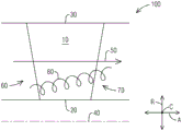
FIG. 2 schematically illustrates a portion of a turbine stage 100 including a turbine having tapered end walls 20, 30Row of vanes, wherein aspects of the invention may be implemented. Similar to the example of FIG. 1, the array of airfoils 10 extends between a circumferentially cascaded platform at the hub side defining the inner endwall 20 and a circumferentially cascaded platform at the tip side defining the outer endwall 30. The inner and outer endwalls 20, 30 define inner and outer diameter boundaries, respectively, of the working medium flow channel 50 between circumferentially adjacent airfoils 10. However, in the illustrated embodiment, the two end walls 20, 30 (or at least the inner end wall 20) are inclined relative to the engine axis 40. The angle of inclination of the inner and outer end walls 20, 30 relative to the engine axis 40 is correspondingly denoted as α 1 And alpha 2 . In particular, as shown, in the present example, the inner end wall 20 is inclined toward the engine axis 40 in a direction from the upstream side 60 to the downstream side 70 relative to the flow of the working medium. The outer end wall 30 is inclined away from the engine axis 40 in a direction from the upstream side 60 to the downstream side 70. Thus, the endwalls 20 and 30 have respective axisymmetric nominal surfaces 26, 36 that are tapered, i.e., form a portion of a cone, such that the flow channels 50 between adjacent airfoils 10 diverge between the upstream and downstream sides 60 and 70. Angle alpha 1 For example, can be in the range of between 5 and 25 degrees, while angle alpha 2 For example, may be in the range of between 10-45 degrees. In the illustrated embodiment, the inner end wall 20 is inclined at an angle α 1 Angle of inclination alpha relative to outer end wall 30 2 Is small.
The inventors have realized that in a conically diverging end wall geometry, such as in the example of fig. 2, the channel vortex tends to rise rapidly away from the end wall and terminate at a higher span (i.e., greater distance from the end wall) than in the case of a cylindrical end wall, resulting in higher secondary losses. This effect is schematically illustrated in fig. 2, wherein the vortex 80 is shown to form at the conical inner end wall 20, which vortex 80 ends at a higher span than the corresponding vortex 80 formed at the cylindrical inner end wall 20 shown in fig. 1. Although not shown in the drawings, a corresponding effect is also observed at the tapered outer end wall 30.
The present inventors have devised an improved non-axisymmetric end wall shape that addresses at least the above-described technical problems applicable to tapered diverging end walls.
With continued reference to fig. 2, one exemplary embodiment of the present invention is illustrated with reference to fig. 3. As shown, the turbine stage 100 includes an array of airfoils 10 extending radially outwardly from an inner end wall 20. Each airfoil 10 is formed from a concave pressure side surface 12 and a laterally opposite convex suction side surface 14 extending between a leading edge 16 and a trailing edge 18. A flow channel 50 is defined between the first airfoil 10a and a circumferentially adjacent second airfoil 10 b.
Referring to FIG. 3, the axial position is 0% Cax ID May be defined as the leading edge position of the airfoil 10 on the inner end wall 20 along the axial direction a. Axial position 100% Cax ID May be defined as the trailing edge position of the airfoil 10 on the inner end wall 20 along the axial direction a. At any given axial position, the circumferential positions are 0% apart ID May be defined as a first location on the inner end wall 20 at the pressure side surface 12 of the first airfoil 10 a. Circumferential position 100% spacing ID May be defined as a second position on the inner end wall 20 at the suction side surface 14 of the circumferentially opposite second airfoil 10b that directly faces said first position at the pressure side surface 12 of the first airfoil 10a in the circumferential direction C.
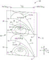
In the illustrated embodiment, the inner end wall 20 is non-axisymmetric, including an intermediate channel bulge 22 between adjacent airfoils 10a and 10 b. A protrusion may be understood as a protrusion or mound extending into the flow path relative to the nominal end wall surface. The protrusion may be formed as a convex surface. In fig. 3, the projections 22 are shown as positive contours having a common elevation from an axisymmetric nominal surface 26 of the inner end wall 20. The projection 22 has a peak 24 defining a point of maximum height h (see fig. 2) measured perpendicularly from a nominal surface 26 of the inner end wall 20. According to the illustrated embodiment, the peak 24 is located at or near the center of the flow channel 50 between adjacent airfoils 10a and 10 b. In particular, peak 24 may be located at 20-60% Cax ID At a position between and at a spacing of 30-70% ID At a location in between.
In a further development, the peaks 24 of the projections 22 can be located in particular at 30-50% Cax ID Between (a) and (b)At the location. In one embodiment, peaks 24 may be particularly located at 40-60% spacing ID At a location in between. The peaks 24 of the projections 22 may have an axial chord length L measured perpendicular to the nominal surface 26 of the inner end wall 20 ID Height h in the range of 3-8%. The bulge 22 may preferably be spaced from the suction side surface 14 of the second airfoil 10 b. That is, from the peaks 24, the protrusions 22 may slope toward the nominal surface 26 in a direction toward the suction side surface 14, merging with the nominal surface 26 at a distance from the suction side surface 14. In the illustrated embodiment, the bulge 22 is closer to the pressure side surface 12 than the suction side surface 14. In some embodiments, the bulge 22 may be further spaced from the pressure side surface 12 of the first airfoil 10 a. That is, from the peaks 24, the protrusions 22 may slope toward the nominal surface 26 in a direction toward the pressure side surface 12 so as to merge with the nominal surface 26 at a distance from the pressure side surface 12.
The inventors have determined that a tapered inner end wall 20 having a large mound or bulge 22 at or near the center of the flow channel 50 between adjacent airfoils 10 (rather than adjacent or near the airfoils) provides increased flow acceleration in otherwise annular decelerated flow channels. Referring to fig. 2, the increased flow acceleration and decreased static pressure attenuate the formation of channel vortices 80 'and pull vortices 80' down to a lower exit span (i.e., closer to end wall 20) while also reducing the pressure gradient laterally across flow channel 50.
While the above embodiments relate to stationary turbine blades, aspects of the invention may be applied to rotating turbine blades, and in particular to a row of blades having a tapered hub-side inner end wall.
As shown in fig. 2 and 4, in a further development, the inventors have determined that in the case of a conical outer end wall 30, the corresponding effects of accelerating the channel flow and weakening the channel vortex can be achieved by: a recess 32 is provided on the outer end wall 30 at or near the center of the flow channel 50 between adjacent airfoils 10.
Referring to FIG. 4, the axial position is 0% Cax OD May be defined as an airfoil 10A leading edge position on the outer end wall 30 in the axial direction a. The axial chord length on the outer end wall 30 is denoted as L OD . Axial position 100% Cax OD May be defined as the trailing edge position of the airfoil 10 on the outer end wall 30 along the axial direction a. At any given axial position, the circumferential positions are 0% apart OD (pitch OD ) May be defined as a first location on the outer end wall 30 at the pressure side surface 12 of the first airfoil 10 a. Circumferential position 100% spacing OD May be defined as a second position on the outer end wall 30 at the suction side surface 14 of the circumferentially opposite second airfoil 10b that directly faces said first position at the pressure side surface 12 of the first airfoil 10a in the circumferential direction C.
In the illustrated embodiment, the outer end wall 30 is non-axisymmetric, including an intermediate channel recess 32 located between adjacent airfoils 10a and 10 b. A depression may be understood as a valley extending away from the flow path relative to the nominal end wall surface. The recess may be formed as a concave surface. In fig. 4, the recess 32 is shown as a negative contour having a common elevation from an axisymmetric nominal surface 36 of the outer end wall 30. The recess 32 has a bottom point 34 defining a point of maximum depth d (see fig. 2) measured perpendicularly from a nominal surface 36 of the outer end wall 30. According to the illustrated embodiment, the bottom point 34 is located at or near the center of the flow channel 50 between adjacent airfoils 10a and 10 b. In particular, the bottom point 34 may be located at 20-60% Cax OD At a position between and at a spacing of 30-70% OD At a location in between. Preferably, the recess 32 may be spaced from the pressure side surface 12 of the first airfoil 10 a. That is, from the bottom point 34, the recess 32 may slope toward the nominal surface 36 in a direction toward the pressure side surface 12, merging with the nominal surface 36 at a distance from the pressure side surface 12. In the illustrated embodiment, the recess 32 is closer to the suction side surface 14 than the pressure side surface 12.
Although specific embodiments have been described in detail, it will be appreciated by those skilled in the art that various modifications and alternatives to those details could be developed in light of the overall teachings of the disclosure. Accordingly, the particular arrangements disclosed are meant to be illustrative only and not limiting as to the scope of the invention which is to be given the full breadth of the appended claims and any and all equivalents thereof.
Claims (12)
1. A turbine stage (100), comprising:
an array of airfoils (10), the airfoils (10) being circumferentially spaced to define flow passages (50) therebetween for guiding a working medium, the airfoils (10) extending radially outwardly from an inner endwall (20) at a hub side thereof,
wherein the axial position is 0% Cax ID Is defined as a leading edge position of the airfoil (10) on the inner end wall (20) along an axial direction of the turbine stage (100), and an axial position of 100% Cax ID Is defined as a trailing edge position of the airfoil (10) on the inner end wall (20) along the axial direction of the turbine stage (100) from an upstream side (60) to a downstream side (70),
wherein at any given axial position, 0% spacing ID Is defined as a first position on the inner end wall (20) at the pressure side surface (12) of the first airfoil (10 a), and 100% spacing ID Is defined as a second position on the inner end wall (20) at a suction side surface (14) of a circumferentially adjacent second airfoil (10 b), which second position faces the first position at the pressure side surface (12) of the first airfoil (10 a) in a circumferential direction (C) of the turbine stage (100),
wherein the inner end wall (20) is tapered and is at an angle (alpha) to the engine axis (40) 1 ) Inclined such that the flow channel (50) diverges from the upstream side (60) to the downstream side (70),
wherein the inner end wall (20) is non-axisymmetric about the engine axis (40) and comprises a bulge (22) between the first airfoil (10 a) and the second airfoil (10 b), the bulge (22) having a diameter of 20-60% Cax ID At a position between and at a spacing of 30-70% ID A peak (24) at a location in between,
wherein the projection (22) is a projection extending into the flow channel (50) relative to the inner end wall (20), and
wherein the inner end wall (20) extends from an upstream side of the inner end wall to the bulge (22) and from the bulge (22) to a downstream side of the inner end wall (20) and defines an entire portion of the inner end wall (20) in the flow channel (50) in cooperation with the bulge (22) to increase the flow acceleration in the flow channel.
2. The turbine stage (100) of claim 1, wherein the peaks (24) of the projections (22) are located at 30-50% cax ID At a location in between.
3. The turbine stage (100) of claim 1, wherein the peaks (24) of the projections (22) are located at 40-60% spacing ID At a location in between.
4. Turbine stage (100) according to claim 1, wherein the peaks (24) of the projections (22) have a chord length (L) in axial direction measured perpendicular to the conical surface (26) of the inner end wall (20) ID ) Height (h) in the range of 3-8%.
5. The turbine stage (100) of claim 1, wherein the bulge (22) is spaced from the suction side surface (14) of the second airfoil (10 b).
6. Turbine stage (100) according to claim 1, wherein the inner end wall (20) is inclined towards the engine axis (40) in a direction from the upstream side (60) to the downstream side (70), the angle of inclination (α) of the inner end wall (20) with respect to the engine axis (40) 1 ) In the range between 5-25 degrees.
7. The turbine stage (100) according to claim 1, further comprising an outer end wall (30) at a tip side of the array of airfoils (10),
wherein the axial position is 0% Cax OD Is defined as the airfoil along the turbineThe axial direction of the stage is at the leading edge position on the outer end wall and the axial position is 100% Cax OD Is defined as a trailing edge position of the airfoil on the outer end wall along the axial direction of the turbine stage from the upstream side to the downstream side,
wherein at any given axial position, 0% spacing OD Is defined as a first position on the outer end wall (30) at the pressure side surface (12) of the first airfoil (10 a), and 100% spacing OD Is defined as a second position on the outer end wall (30) at the suction side surface (14) of the second airfoil (10 b) facing the first position at the pressure side surface (12) of the first airfoil (10 a) in the circumferential direction (C) of the turbine stage (100),
wherein the outer end wall (30) is at an angle (alpha) relative to the engine axis (40) 2 ) Inclined such that the flow channel (50) diverges from the upstream side (60) to the downstream side (70), and
wherein the outer end wall (30) is non-axisymmetric about the engine axis (40) and comprises an intermediate passage recess (32) between the first airfoil (10 a) and the second airfoil (10 b), the recess (32) having a cavity in the range of 20-60% Cax OD At a position between and at a spacing of 30-70% OD A bottom point (34) at a location therebetween.
8. The turbine stage (100) of claim 7, wherein the recess (32) is spaced from the pressure side surface (12) of the first airfoil (10 a).
9. The turbine stage (100) of claim 7, wherein the inner end wall (20) is inclined at an angle (a) relative to the engine axis (40) 1 ) An angle of inclination (alpha) relative to the engine axis (40) than the outer end wall (30) 2 ) Is small.
10. The turbine stage (100) of claim 7, wherein the outer end wall (30) extends from theThe upstream side (60) to the downstream side (70) being inclined away from the engine axis (40), the outer end wall (30) being inclined at an angle (alpha) relative to the engine axis (40) 2 ) In the range between 10-45 degrees.
11. The turbine stage (100) of claim 1, wherein the array of airfoils (10) is part of a row of stationary turbine buckets.
12. The turbine stage (100) of claim 1, wherein the array of airfoils (10) is part of a row of rotating turbine blades.
Applications Claiming Priority (1)
| Application Number | Priority Date | Filing Date | Title |
|---|---|---|---|
| PCT/US2018/025310 WO2019190540A1 (en) | 2018-03-30 | 2018-03-30 | Endwall contouring for a conical endwall |
Publications (2)
| Publication Number | Publication Date |
|---|---|
| CN111936722A CN111936722A (en) | 2020-11-13 |
| CN111936722B true CN111936722B (en) | 2023-04-28 |
Family
ID=62002500
Family Applications (1)
| Application Number | Title | Priority Date | Filing Date |
|---|---|---|---|
| CN201880092109.9A Active CN111936722B (en) | 2018-03-30 | 2018-03-30 | End wall shaping for conical end walls |
Country Status (5)
| Country | Link |
|---|---|
| US (1) | US11560797B2 (en) |
| EP (1) | EP3759318A1 (en) |
| JP (1) | JP7230058B2 (en) |
| CN (1) | CN111936722B (en) |
| WO (1) | WO2019190540A1 (en) |
Families Citing this family (3)
| Publication number | Priority date | Publication date | Assignee | Title |
|---|---|---|---|---|
| US11415012B1 (en) | 2021-09-03 | 2022-08-16 | Pratt & Whitney Canada Corp. | Tandem stator with depressions in gaspath wall |
| US11639666B2 (en) * | 2021-09-03 | 2023-05-02 | Pratt & Whitney Canada Corp. | Stator with depressions in gaspath wall adjacent leading edges |
| CN114991876B (en) * | 2022-07-15 | 2023-07-07 | 北京航空航天大学 | Partial crown turbine blade crown circumferential modeling design method |
Citations (5)
| Publication number | Priority date | Publication date | Assignee | Title |
|---|---|---|---|---|
| US20070258819A1 (en) * | 2006-05-02 | 2007-11-08 | United Technologies Corporation | Airfoil array with an endwall protrusion and components of the array |
| CN103321686A (en) * | 2012-03-23 | 2013-09-25 | 通用电气公司 | Scalloped surface turbine stage |
| US20140348660A1 (en) * | 2013-05-24 | 2014-11-27 | MTU Aero Engines AG | Blade cascade and continuous-flow machine |
| CN106988797A (en) * | 2015-11-11 | 2017-07-28 | 通用电气公司 | System for the section of the integration of turbine |
| US20170226877A1 (en) * | 2016-02-09 | 2017-08-10 | General Electric Company | Turbine nozzle profile |
Family Cites Families (39)
| Publication number | Priority date | Publication date | Assignee | Title |
|---|---|---|---|---|
| US4677828A (en) * | 1983-06-16 | 1987-07-07 | United Technologies Corporation | Circumferentially area ruled duct |
| DE19650656C1 (en) * | 1996-12-06 | 1998-06-10 | Mtu Muenchen Gmbh | Turbo machine with transonic compressor stage |
| JPH10184304A (en) * | 1996-12-27 | 1998-07-14 | Toshiba Corp | Turbine nozzle and turbine moving blade of axial flow turbine |
| JP4241937B2 (en) * | 1997-04-01 | 2009-03-18 | シーメンス アクチエンゲゼルシヤフト | Steam turbine and steam turbine blades |
| SE9904603D0 (en) * | 1999-12-16 | 1999-12-16 | Atlas Copco Tools Ab | Turbine engine for elastic fluid operation |
| DE102004036594A1 (en) * | 2004-07-28 | 2006-03-23 | Mtu Aero Engines Gmbh | Flow structure for a gas turbine |
| WO2006033407A1 (en) * | 2004-09-24 | 2006-03-30 | Ishikawajima-Harima Heavy Industries Co., Ltd. | Wall shape of axial flow machine and gas turbine engine |
| US7722329B2 (en) * | 2005-12-29 | 2010-05-25 | Rolls-Royce Power Engineering Plc | Airfoil for a third stage nozzle guide vane |
| US7648334B2 (en) * | 2005-12-29 | 2010-01-19 | Rolls-Royce Power Engineering Plc | Airfoil for a second stage nozzle guide vane |
| US8511978B2 (en) * | 2006-05-02 | 2013-08-20 | United Technologies Corporation | Airfoil array with an endwall depression and components of the array |
| US8313291B2 (en) * | 2007-12-19 | 2012-11-20 | Nuovo Pignone, S.P.A. | Turbine inlet guide vane with scalloped platform and related method |
| US8647067B2 (en) * | 2008-12-09 | 2014-02-11 | General Electric Company | Banked platform turbine blade |
| US8459956B2 (en) | 2008-12-24 | 2013-06-11 | General Electric Company | Curved platform turbine blade |
| US8231353B2 (en) * | 2008-12-31 | 2012-07-31 | General Electric Company | Methods and apparatus relating to improved turbine blade platform contours |
| EP2261462A1 (en) * | 2009-06-02 | 2010-12-15 | Alstom Technology Ltd | End wall structure for a turbine stage |
| US8439643B2 (en) * | 2009-08-20 | 2013-05-14 | General Electric Company | Biformal platform turbine blade |
| FR2950942B1 (en) * | 2009-10-02 | 2013-08-02 | Snecma | ROTOR OF A TURBOMACHINE COMPRESSOR WITH OPTIMIZED INTERNAL END WALL |
| US8591184B2 (en) * | 2010-08-20 | 2013-11-26 | General Electric Company | Hub flowpath contour |
| DE102011006273A1 (en) * | 2011-03-28 | 2012-10-04 | Rolls-Royce Deutschland Ltd & Co Kg | Rotor of an axial compressor stage of a turbomachine |
| DE102011006275A1 (en) * | 2011-03-28 | 2012-10-04 | Rolls-Royce Deutschland Ltd & Co Kg | Stator of an axial compressor stage of a turbomachine |
| US8721291B2 (en) * | 2011-07-12 | 2014-05-13 | Siemens Energy, Inc. | Flow directing member for gas turbine engine |
| US8807930B2 (en) * | 2011-11-01 | 2014-08-19 | United Technologies Corporation | Non axis-symmetric stator vane endwall contour |
| US9194235B2 (en) * | 2011-11-25 | 2015-11-24 | Mtu Aero Engines Gmbh | Blading |
| WO2014028056A1 (en) * | 2012-08-17 | 2014-02-20 | United Technologies Corporation | Contoured flowpath surface |
| US20160146601A1 (en) * | 2012-09-28 | 2016-05-26 | United Technologies Corporation | Throat area calculation for a section of a gas turbine engine |
| US9311445B2 (en) * | 2012-11-20 | 2016-04-12 | General Electric Company | Method, process, and system for high efficiency gas turbine exhaust duct flow-path |
| US9879540B2 (en) * | 2013-03-12 | 2018-01-30 | Pratt & Whitney Canada Corp. | Compressor stator with contoured endwall |
| ES2755052T3 (en) * | 2013-08-06 | 2020-04-21 | MTU Aero Engines AG | Blade grating and corresponding turbomachine |
| EP3158167B1 (en) * | 2014-06-18 | 2020-10-07 | Siemens Energy, Inc. | End wall configuration for gas turbine engine |
| JP2016040463A (en) * | 2014-08-13 | 2016-03-24 | 株式会社Ihi | Axial flow type turbo machine |
| US9926806B2 (en) * | 2015-01-16 | 2018-03-27 | United Technologies Corporation | Turbomachine flow path having circumferentially varying outer periphery |
| WO2017018981A1 (en) * | 2015-07-24 | 2017-02-02 | Siemens Aktiengesellschaft | Turbine blade with contoured tip shroud |
| US10161255B2 (en) * | 2016-02-09 | 2018-12-25 | General Electric Company | Turbine nozzle having non-axisymmetric endwall contour (EWC) |
| US10221710B2 (en) * | 2016-02-09 | 2019-03-05 | General Electric Company | Turbine nozzle having non-axisymmetric endwall contour (EWC) and profile |
| EP3404210A1 (en) * | 2017-05-15 | 2018-11-21 | MTU Aero Engines GmbH | Blade cascade segment for a turbomachine with non-axisymmetric platform surface, corresponding blade cascade, blade channel, platform, and turbomachine |
| US10508550B2 (en) * | 2017-10-25 | 2019-12-17 | United Technologies Corporation | Geared gas turbine engine |
| US10689993B2 (en) * | 2018-11-15 | 2020-06-23 | General Electric Company | Airfoil shape for turbine nozzles |
| US10968748B2 (en) * | 2019-04-08 | 2021-04-06 | United Technologies Corporation | Non-axisymmetric end wall contouring with aft mid-passage peak |
| JP2021127755A (en) * | 2020-02-17 | 2021-09-02 | 三菱重工業株式会社 | Two-shaft gas turbine |
-
2018
- 2018-03-30 WO PCT/US2018/025310 patent/WO2019190540A1/en unknown
- 2018-03-30 JP JP2020552885A patent/JP7230058B2/en active Active
- 2018-03-30 EP EP18718371.0A patent/EP3759318A1/en active Pending
- 2018-03-30 CN CN201880092109.9A patent/CN111936722B/en active Active
- 2018-03-30 US US17/040,167 patent/US11560797B2/en active Active
Patent Citations (5)
| Publication number | Priority date | Publication date | Assignee | Title |
|---|---|---|---|---|
| US20070258819A1 (en) * | 2006-05-02 | 2007-11-08 | United Technologies Corporation | Airfoil array with an endwall protrusion and components of the array |
| CN103321686A (en) * | 2012-03-23 | 2013-09-25 | 通用电气公司 | Scalloped surface turbine stage |
| US20140348660A1 (en) * | 2013-05-24 | 2014-11-27 | MTU Aero Engines AG | Blade cascade and continuous-flow machine |
| CN106988797A (en) * | 2015-11-11 | 2017-07-28 | 通用电气公司 | System for the section of the integration of turbine |
| US20170226877A1 (en) * | 2016-02-09 | 2017-08-10 | General Electric Company | Turbine nozzle profile |
Also Published As
| Publication number | Publication date |
|---|---|
| WO2019190540A1 (en) | 2019-10-03 |
| JP7230058B2 (en) | 2023-02-28 |
| EP3759318A1 (en) | 2021-01-06 |
| CN111936722A (en) | 2020-11-13 |
| US20210115798A1 (en) | 2021-04-22 |
| US11560797B2 (en) | 2023-01-24 |
| JP2021526606A (en) | 2021-10-07 |
Similar Documents
| Publication | Publication Date | Title |
|---|---|---|
| US7371046B2 (en) | Turbine airfoil with variable and compound fillet | |
| US10415392B2 (en) | End wall configuration for gas turbine engine | |
| EP2423438A2 (en) | Shrouded turbine blade with contoured platform and axial dovetail | |
| US20110044818A1 (en) | Biformal platform turbine blade | |
| CN111315962B (en) | Turbine blade and corresponding method of repair | |
| CN111936722B (en) | End wall shaping for conical end walls | |
| US11739644B2 (en) | Turbine stage platform with endwall contouring incorporating wavy mate face | |
| CN106907185B (en) | Protruding nozzle for controlling secondary flow and optimum diffuser performance | |
| US11365638B2 (en) | Turbine blade and corresponding method of servicing | |
| EP3722555B1 (en) | Turbine section having non-axisymmetric endwall contouring with forward mid-passage peak | |
| EP3740656B1 (en) | Article of manufacture | |
| US11053804B2 (en) | Shroud interlock | |
| CN112943383A (en) | Turbine nozzle with airfoil having curved trailing edge | |
| WO2019035800A1 (en) | Turbine blades |
Legal Events
| Date | Code | Title | Description |
|---|---|---|---|
| PB01 | Publication | ||
| PB01 | Publication | ||
| SE01 | Entry into force of request for substantive examination | ||
| SE01 | Entry into force of request for substantive examination | ||
| TA01 | Transfer of patent application right | ||
| TA01 | Transfer of patent application right |
Effective date of registration: 20220609 Address after: Munich, Germany Applicant after: Siemens energy global Corp. Address before: Munich, Germany Applicant before: SIEMENS AG |
|
| GR01 | Patent grant | ||
| GR01 | Patent grant |