Disclosure of Invention
The invention aims to provide a complex mountain area long and deep buried tunnel surveying method based on a sky ground surveying technology, and by adopting a sky ground multi-source surveying technical method, the surveying problem caused by an external environment can be effectively solved, and the surveying precision and efficiency are improved.
The technical scheme adopted by the invention is as follows:
a complex mountain area long and deep buried tunnel exploration method based on a sky reconnaissance technology is characterized by comprising the following steps:
the method comprises the following steps:
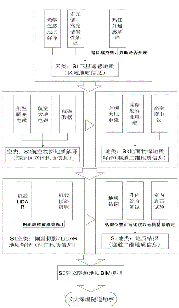
s1, performing satellite remote sensing geological interpretation: carrying out satellite optical remote sensing along the axis of the tunnel to obtain remote sensing image data of a work point, and carrying out geological interpretation according to the remote sensing image data;
s2, performing aerial geophysical prospecting geological interpretation: specifically, developing an aviation geophysical prospecting along the axis of a tunnel, acquiring aviation transient electromagnetic data, aviation magnetotelluric data and aeromagnetic data of a work point, developing three-dimensional joint inversion to establish a three-dimensional data model, and performing three-dimensional geological interpretation of a tunnel site area;
and S3, performing ground geophysical prospecting geological interpretation: carrying out ground geophysical prospecting in a tunnel field area by combining field conditions with remote sensing and aviation geophysical prospecting geological interpretation results, and acquiring geophysical prospecting data and carrying out geological interpretation;
s4, developing unmanned aerial vehicle remote sensing geology at the tunnel portal: carrying out three-dimensional oblique photography or unmanned aerial vehicle-mounted LiDAR at the main line of the tunnel and the opening of the auxiliary tunnel by combining site conditions and on-site geological mapping results, and acquiring image data and carrying out geological interpretation;
s5, obtaining drilling geological information: combining site conditions with remote sensing, aviation geophysical prospecting and ground geophysical prospecting geological interpretation results, selecting a representative section and a geophysical prospecting abnormal point to drill, and simultaneously performing deep hole comprehensive testing and sampling in a drill hole to perform geotechnical test to obtain tunnel deep geological information;
s6, establishing a tunnel geology BIM model: and according to geological information obtained in the steps of S1, S2, S3, S4 and S5, tunnel geological BIM modeling is carried out by combining mapping data and a design scheme, and tunnel design and construction are guided.
In the step S1, the method includes the following steps:
s1a1, according to geological data of a work point research area, carrying out satellite optical remote sensing geological interpretation, and mainly interpreting geological information of landform, fracture structure and unfavorable geology of the research area;
s1a2, performing hyperspectral multispectral lithology interpretation according to the satellite optical remote sensing geological interpretation result, and mainly interpreting the lithology and lithology rock groups of the stratum in the research area;
s1a3, preliminarily analyzing whether the research area has geothermal abnormality or not according to the regional structure of the work point research area and geothermal data, if so, developing high-resolution thermal infrared remote sensing interpretation, mainly acquiring the earth surface temperature of the research area, and dividing geothermal abnormality zones; if the infrared remote sensing interpretation does not exist, the high-resolution thermal infrared remote sensing interpretation is not carried out.
In the step S2, the aerial geophysical prospecting geological interpretation includes the following steps:
s2a1, according to the principle of an aerial geophysical prospecting line, according to geological data of a work point research area, the aerial geophysical prospecting line arrangement is carried out along the axis of a tunnel, 9 hard rock surveying lines are arranged, and 11 soft rock surveying lines are arranged;
s2a2, acquiring aerial geophysical prospecting data, carrying out aviation flight along different measuring lines by adopting a helicopter to carry aeromagnetic method instrument equipment and aeromagnetic equipment, and acquiring the aerial geophysical prospecting data information of the different measuring lines in a tunnel research area;
s2a3, processing aerial geophysical prospecting data, specifically processing aerial transient electromagnetic data, aerial magnetotelluric data and aerial magnetotelluric data to obtain three-dimensional data;
and S2a4, performing aerial geophysical prospecting interpretation, namely performing geological interpretation along the axial section of the tunnel and along the elevation plane of the tunnel on the three-dimensional data according to the aerial transient electromagnetic, aerial magnetotelluric and aerial magnetomagnetic three-dimensional data generated by processing in the step S2a3 and combining regional geological data, remote sensing geology and ground mapping results to obtain aerial geophysical prospecting geological information of the tunnel region.
In the step S3, the ground geophysical prospecting geological interpretation includes the following steps:
s3a1, acquiring ground geophysical prospecting data, and performing ground geophysical prospecting work by adopting ground geophysical prospecting equipment along a tunnel axis or a measuring line closely related to the geological condition of the tunnel to acquire ground geophysical prospecting data information of a tunnel research area along the axial direction of the tunnel or other measuring line directions intersecting the tunnel;
s3a2, processing ground geophysical prospecting data, editing the data collected on site to remove unreasonable data, and then performing inversion and constraint processing on the data of the audio geodetic electromagnetic method obtained by ground geophysical prospecting;
and S3a3, performing ground geophysical prospecting interpretation, interpreting the ground geophysical prospecting inverted resistivity section result according to the ground geophysical prospecting inverted resistivity section result generated in the step S3a2 and combining regional geological data, remote sensing geology and ground mapping results, and mainly acquiring geological information of lithologic contact zones, fault structures, namely toughness shear zones, joint dense zones, lithologic groups, karsts and water-rich property near the tunnel.
In the step S4, the remote sensing geological interpretation of the tunnel portal by the unmanned aerial vehicle comprises the following steps:
s4a1, selecting an unmanned aerial vehicle remote sensing method at the tunnel portal, selecting different remote sensing interpretation methods aiming at different vegetation coverage of the place where the tunnel portal is located, and if the vegetation coverage rate is low and the earth surface is bare, adopting airborne three-dimensional oblique photography; if the vegetation coverage rate is high and the ground vegetation coverage is serious, adopting airborne LiDAR;
s4a2, acquiring airborne oblique photography or airborne LiDAR data of the unmanned aerial vehicle at the tunnel portal, and acquiring high-precision data influencing surface images, coordinates and elevations within the range of the tunnel portal by carrying out aviation flight work through the airborne oblique photography or airborne LiDAR equipment of the unmanned aerial vehicle;
s4a3, processing airborne oblique photography or airborne LiDAR data of the unmanned aerial vehicle, processing field collected images and elevation data, mainly comprising three-dimensional modeling, coordinate conversion and splicing matching, and finally generating three-dimensional oblique photography and three-dimensional LiDAR data which can be directly used in a three-dimensional platform;
and S4a4, oblique photography and LiDAR geological interpretation of the cave entrance unmanned aerial vehicle, wherein according to the cave entrance unmanned aerial vehicle oblique photography and LiDAR results generated in the steps S4a2 and S4a3, detailed delineation is carried out on the cave entrance earth surface geological disasters, and the attitude of the rock mass structural plane is extracted so as to obtain the cave entrance earth surface disasters and the geological information of the rock mass structural plane.
In the step S5, geological drilling information is acquired, which includes the following steps:
s5a1, determining a drilling position, obtaining a geological interpretation result by combining S1, S2, S3 and S4, determining the drilling position of the tunnel body, and laying and drilling mainly aiming at the fracture structure development, water-rich and geophysical abnormal sections, wherein the drilling position comprises a vertical hole and a directional hole;
s5a2, drilling core acquisition, drilling according to the arrangement position, and acquiring core data which mainly comprises lithology, rock mass crushing degree, RQD, karst and cavities;
s5a3, performing drilling comprehensive test, performing in-hole comprehensive test on the implemented deep hole, and acquiring data of rock mass resistivity, acoustic wave velocity, ground temperature, ground stress, water-rich property and harmful gas;
and S5a4, carrying out geotechnical tests and other special tests, carrying out representative sampling on the implemented deep-hole core, carrying out tests of mechanics, radioactivity and year measurement on the deep-hole core, and acquiring geological information of rock mechanics parameters, radioactivity and age.
S6, establishing a tunnel geology BIM model in the step, and the method comprises the following steps:
s6a1, finishing geological information acquired in the steps S1, S2, S3, S4 and S5, filling and drawing a geological plan map and a geological longitudinal section map, and adding a controlled geological section at a key engineering part and a part with a complex geological phenomenon according to BIM modeling requirements to form a two-dimensional geological result of tunnel engineering;
s6a2, delineating the engineering range of the tunnel address area, and taking 500m and 1000m at two sides of the center of the line as required; and establishing a three-dimensional terrain model of the tunnel address area by adopting a topographic map of the tunnel address area or DEM data, and generating a three-dimensional terrain body of the tunnel address area by combining the boundary surface. Projecting elements of the geological boundary in the geological plan of the tunnel site area to the surface of the three-dimensional terrain by utilizing space projection; combining the line and the three-dimensional terrain, and transforming the tunnel geological profile and the geological profile into a three-dimensional space;
and S6a3, combining the three-dimensional terrain surface geological boundary, the three-dimensional space geological section and the geological profile, and generating a stratum interface by using an interpolation algorithm. And according to the tunnel address area three-dimensional geologic body generated by S6a2, utilizing Boolean operation to dissect and generate each geologic body related to the tunnel, and giving attribute information of each geologic body on the basis to complete the establishment of the tunnel geological BIM model.
The invention has the following advantages:
1. the multisource three-dimensional exploration method for the long and large deep buried tunnel is established based on the exploration technologies such as space satellite remote sensing, air space airborne geophysical prospecting, unmanned aerial vehicle remote sensing, ground geophysical prospecting, deep hole drilling, directional hole and deep hole testing, the defects of difficult conventional exploration means and low efficiency in high-altitude, high-cold and large-altitude-difference areas are overcome, and the full coverage of the exploration data of the long and large deep buried tunnel is ensured.
2. The three-dimensional exploration method provided by the invention realizes the integration of three parts from surface to line and then to point, improves the accuracy and precision of exploration and provides a strong technical support for the design and construction of long and large deep-buried projects.
Detailed Description
The present invention will be described in detail with reference to specific embodiments.
Under the influence of the aspects of terrain, traffic, buried depth, ice and snow coverage, severe weather and the like, the conventional exploration means, the conventional exploration technology and the conventional exploration method are difficult to meet the requirements of large and deep tunnel engineering in a hard mountain area, such as incapability of reaching geological survey personnel, incapability of fully covering ground geophysical prospecting, incapability of running through along the axis of a cavern, large limitation of vertical deep hole drilling, no implementation condition in part of areas, low working efficiency, more limitation and large blind area of the conventional exploration means.
The invention relates to a long and long deep buried tunnel surveying method based on sky ground surveying technology, which is mainly based on the surveying technologies such as space satellite remote sensing, space aviation geophysical prospecting, unmanned aerial vehicle remote sensing, ground geophysical prospecting, deep hole drilling, directional hole and deep hole testing and the like to carry out multi-source three-dimensional surveying on a long and long deep buried tunnel. The method comprises the following specific steps:
referring to fig. 1, the present invention is performed as follows:
the method comprises the following steps:
s1, performing satellite remote sensing geological interpretation: specifically, satellite optical remote sensing geology is developed along the axis of the tunnel, work point remote sensing image data is obtained, and geological interpretation is carried out according to the remote sensing image data.
S2, performing aerial geophysical prospecting geological interpretation: specifically, the method comprises the steps of developing aerial geophysical prospecting along the axis of a tunnel, obtaining aerial transient electromagnetic data, aerial magnetotelluric data and aerial magnetic data of a work point, developing three-dimensional joint inversion, establishing a three-dimensional data model, and performing geological interpretation.
And S3, performing ground geophysical prospecting geological interpretation: and carrying out ground geophysical prospecting in the tunnel field area by combining field conditions with remote sensing and aviation geophysical prospecting geological interpretation results, and acquiring geophysical prospecting data and carrying out geological interpretation.
S4, developing unmanned aerial vehicle remote sensing geology at the tunnel portal: and (3) carrying out three-dimensional oblique photography or unmanned aerial vehicle-mounted LiDAR at the main line of the tunnel and the opening of the auxiliary gallery by combining site conditions and on-site geological mapping results, acquiring image data and carrying out geological interpretation.
S5, obtaining drilling geological information: and selecting a representative section and a geophysical abnormal point to drill by combining site conditions and remote sensing, aviation geophysical prospecting and ground geophysical prospecting geological interpretation results, and simultaneously performing deep hole comprehensive test and indoor geotechnical test in a drill hole to obtain the deep geological information of the tunnel.
S6, establishing a tunnel geology BIM model: according to the geological information obtained in the steps, tunnel geological BIM modeling is carried out by combining surveying and mapping data and a design scheme, and tunnel design and construction are guided.
The steps are as follows:
in the step S1, preparation work is required, including the following steps:
s1a1, according to geological data of the work point research area, the satellite optical remote sensing geology is developed, and geological information such as landform, fracture structure, unfavorable geology and the like of the research area is mainly interpreted.
S1a2, according to the satellite optical remote sensing geological interpretation result, carrying out hyperspectral multispectral lithology interpretation and mainly interpreting the lithology and lithology rock groups of the stratum in the research area.
S1a3, preliminarily analyzing whether the research area has geothermal abnormality or not according to the regional structure of the work point research area and geothermal data, if so, developing high-resolution thermal infrared remote sensing interpretation, mainly acquiring the earth surface temperature of the research area, and dividing geothermal abnormality zones; if the infrared remote sensing interpretation does not exist, the high-resolution thermal infrared remote sensing interpretation is not carried out.
In the step S1a1, the main work flow of the satellite optical remote sensing geology is as follows:
A. and (3) acquiring regional remote sensing data, namely collecting 1:5 ten thousand (the widths of two sides are about 15km respectively) and 1:1 thousand (the widths of two sides are about 2km respectively) multi-period multi-source optical satellite remote sensing images along the axis of the tunnel, wherein the collected satellite image data are required to be clear, a snow cover area is only arranged above a snow line, and a cloud layer covers a part of the area and basically has no interference strips.
B. Processing and making remote sensing images, namely completing image making by adopting methods such as geometric fine correction, color matching, image mosaic and the like; extracting rock types or type combinations through lithology and structural information enhancement processing; the terrain is extracted through the DEM, so that the change of the terrain and the landform, the linear characteristic change and the deformation of the micro landform can be directly reflected to directly reflect the existence of the fracture; and (3) identifying the distribution and structure of geological phenomena by applying various image information enhancement processing schemes and combining a three-dimensional remote sensing technology according to collected multi-source data, and extracting engineering geological information.
C. And (3) performing preliminary interpretation, namely establishing a direct interpretation mark according to the shape, size, tone and color, shadow, image structure, pattern and pattern of the image by adopting a method such as an interpretation method, a comparison method, a logic reasoning method, an image processing method, a comprehensive analysis method, an Olympic interactive map assisted interpretation method, a DEM (digital elevation model) terrain extraction assisted interpretation method and the like, performing remote sensing interpretation on the landform, the stratigraphic lithology, the structure, the hydrogeology, the unfavorable geology and the special geology of the whole area, accurately drawing the landform and boundary lines of various geologic bodies, and delineating the boundary and distribution range of various unfavorable geologies and special geologies.
D. And (3) field investigation and verification, wherein the field investigation and verification are carried out on the primary interpretation results, representative and typical geologic bodies are selected for field verification, 10% of the primary interpretation results are extracted from unfavorable geology for verification, and 100% of field verification is carried out on large and medium-sized unfavorable geology points near the tunnel portal.
E. And secondary interpretation, namely reinterpreting and delineating the landform, the lithology of the stratum, the structure, the hydrogeology, the unfavorable geology and the special geology of the work point area according to the results of the primary interpretation and the field investigation and verification.
In the step S1a2, the main workflow of hyperspectral lithology interpretation is as follows:
A. acquiring remote sensing data, namely collecting 1:5 thousands (the width of two sides is about 15km respectively) of multi-period multi-source hyperspectral and multispectral remote sensing images, images in different time periods are selected, different wave band combinations are compared and analyzed, and the influence of cloud shadow, snow cover and vegetation is eliminated as much as possible.
B. The remote sensing image preprocessing is mainly used for geometric fine correction of images, image mosaic, image cutting, atmospheric correction and the like. In the image correction process, the projection mode adopts Gaussian-Kruger projection. And performing geometric correction, seamless mosaic, color tone matching and the like on the image scene by scene.
C. Establishing lithology spectrum characteristics and a spectrum library, carrying out field site reconnaissance, collecting typical rocks and minerals in a tunnel region, carrying out spectrum test, and establishing the spectrum library.
D. The remote sensing image processing and interpretation, the enhancement processing is carried out on the remote sensing image, the useful information in the image is highlighted, the difference between different image characteristics is enlarged, the image interpretation and analysis capability is improved, and the lithology interpretation of a work point area is carried out through the wave-front inversion.
E. And field investigation and verification, wherein the field investigation and verification are carried out on the primary interpretation result, representative and typical lithology is selected for field verification, and field verification is carried out on each type of lithology.
F. And secondary interpretation, namely reinterpreting and delineating the lithology of the work point area, particularly the boundary part according to the results of the primary interpretation and the field investigation and verification.
In the step S1a3, the main workflow of thermal infrared remote sensing interpretation is as follows:
A. the method comprises the steps of preliminarily analyzing the geothermal characteristics of a research area, namely preliminarily analyzing whether geothermal abnormality exists in a work point range or not by collecting relevant data such as regional geology, geothermal resources and the like and combining field hot spring investigation and remote sensing geological structure interpretation, if the geothermal abnormality does not exist, the thermal infrared remote sensing interpretation can not be carried out, and if the geothermal abnormality possibly exists, the thermal infrared remote sensing interpretation work is carried out.
B. And (3) acquiring remote sensing data, namely collecting 1:5 ten thousand (the width of two sides is about 15km respectively) high-resolution multi-period thermal infrared remote sensing data in a section where the tunnel site research area possibly has geothermal abnormality.
C. The remote sensing image processing and the surface temperature preliminary calculation are mainly carried out for radiometric calibration, atmospheric correction, image cutting, geometric correction, vegetation interference factor removal, surface temperature calculation and the like.
D. And (3) field temperature measurement and verification, wherein the field real-time temperature measurement and verification are carried out on the preliminary calculation result of the surface temperature, and representative and typical geothermal abnormal points are selected for field verification.
E. And secondary interpretation, namely recalculating and inverting the surface temperature of the work point area according to the primary calculation result of the surface temperature and the field investigation and verification result, and re-interpreting and delineating the geothermal abnormal area.
In the step S2, the aerial geophysical prospecting geological interpretation includes the following steps:
s2a1, according to the principle of an aerial geophysical prospecting line, according to geological data of a work point research area, the aerial geophysical prospecting line arrangement is carried out along the axis of a tunnel, 9 hard rock surveying lines are arranged, and 11 soft rock surveying lines are arranged;
and S2a2, acquiring aerial geophysical prospecting data, carrying aerial electromagnetic method instrument equipment and aeromagnetic equipment on a helicopter to carry out aviation flight along different measuring lines, and acquiring aerial geophysical prospecting data information of different measuring lines in a tunnel research area.
And S2a3, processing aerial geophysical prospecting data, and processing aerial transient electromagnetic data, aerial magnetotelluric data and aerial magnetic data.
And S2a4, performing aerial geophysical prospecting interpretation, namely performing geological interpretation on the three-dimensional data along the axial section of the tunnel and the elevation plane of the tunnel according to the aerial transient electromagnetic, aerial magnetotelluric and aerial magnetomagnetic three-dimensional data generated by processing in the step S2a3 and combining regional geological data and ground mapping results to obtain aerial geophysical prospecting geological information near the tunnel.
In the step S2a3, the main workflow of processing the aviation transient electromagnetic data is as follows:
A. and correcting the position of the recording point, and correcting the time lag and the position offset. A certain time delay exists between the signal transmission and the signal reception, and the time delay can generate a certain offset of the position of the recording point; when the flying directions are different, due to wind and the like, the received position of the sensor and the GPS coordinate of the recording measuring point have different degrees of deviation, so that the recording point abnormity has certain deviation from the actual abnormal position, and certain correction is performed on the deviation.
B. The calculation of the time constant, the time constant of the abnormal body determines the size of the transient field decay rate, and is an important parameter for determining the electrical property of the abnormal body.
The time constants of the dB/dt and B fields are calculated by using a 'moving time constant' method. The calculation principle is based on finding the appropriate 4 time-channels late, using a moving window, from a sliding decay curve that responds in noise level and decay. The time constant is obtained by least squares fitting these 4 time channels.
C. Resistivity Depth Imaging (RDI), which is a method for rapidly transforming electromagnetic response attenuation data into Resistivity depth profiles in the same sense by deconvoluting the measured data. The RDI algorithm for resistivity-depth conversion employed is based on the apparent resistivity conversion of Maxwell a. meju (1998) and the TEM response principle of the conductive half-space.
The RDI can provide information of conductor depth, vertical extension and the like with reference values, and can accurately provide one-dimensional laminar dielectric apparent resistivity sections on each measuring line. According to the RDI, the data of the VTEM system such as the detection depth, the half-space secondary field distribution, the effective resistivity, the initial geometric form, the position of the electric conductor and the like can be obtained.
In the step S2a3, the main workflow of the aviation magnetotelluric data processing is as follows:
A. in the calculation, the natural electromagnetic method of vertical incidence will generate a vertical magnetic field component in a transversely inhomogeneous medium, and the vertical magnetic field component and two horizontal magnetic field components have the following complex linear relationship:
in the formula:
Hx、Hy、Hz-horizontal X, Y, vertical Z-direction magnetic field component;
T=[Tzx Tzy]-a tilt sub-vector;
tzx, Tzy-represent the components of the tilt T in the inline direction (X) and the perpendicular inline direction (Y).
According to theory, the real part (In-phase, In-phase component) of the tilter can well reflect the transverse non-uniformity of the medium and the geometric form of the target body; while the imaginary component (Quadrature component) of the dip is related to the electrical properties of the target volume. The change in lateral resistivity affects the magnitude of the real and imaginary parts of the dip. The real part of the tilt data shows positive abnormality at the horizontal electric interface from low resistance to high resistance, and shows negative abnormality at the horizontal electric interface from high resistance to low resistance. The imaginary part shows negative abnormality at the transverse electric interface from low resistance to high resistance, and shows positive abnormality at the transverse electric interface from high resistance to low resistance. The amplitudes are all represented as positive anomaly information. The boundaries of multiple anomalies can be distinguished and interpreted by utilizing the characteristics of the inclinations.
The amplitude response curve carries rich information about the subsurface geologic volume. This data is processed as the basis for the next mapping and resistivity inversion.
B. TD (Total derivative) total divergence calculation, TD being obtained by the derivative of the dip in the inline direction (X) and the perpendicular inline direction (Y), is as follows:
C. tpr (total phase rotated) total phase rotation calculation, pr (phase rotation) is to process the tilt data of each frequency along the line measuring direction (X) and the perpendicular line measuring direction (Y) by using the phase rotation technique, convert the bipolar field abnormal response into the unipolar field abnormal response, and generate a maximum value at the center position of the corresponding abnormal zone. The Total Phase Rotation (TPR) of the in-Phase and out-of-Phase components of each frequency is typically obtained by integrating two quadrature grids after Phase Rotation. The TPR can make up for the shortage of TD data.
D. And (3) performing apparent resistivity inversion, namely selecting more reasonable background resistivity to perform inversion by using real part and imaginary part dip data along the direction of a measuring line, performing terrain correction, flight height correction and the like during inversion, and measuring an inversion result by using an input error.
In the step S2a3, the main workflow of aeromagnetic data processing is as follows:
A. and correction processing, namely the correction processing of the aeromagnetic data is mainly the calculation of delta T magnetic anomaly. The correction processing of the aeromagnetic data comprises normal geomagnetic field correction, magnetic diurnal variation correction and the like.
And (3) normal geomagnetic field correction: the used international geomagnetic reference field is IGRF2015 (the effective service life is 2015-2019), the measured longitude and latitude and the GPS height are respectively used for each magnetic measurement point to calculate the normal magnetic field value of the corresponding point, and normal geomagnetic field correction is completed on the basis.
Magnetic diurnal variation correction: and editing the magnetic diurnal variation data which is synchronously observed, eliminating the human interference data, filtering and correcting point by point.
B. Data leveling, the measured data and the line measurement data corrected by various items are influenced by factors such as measurement height, flight direction and the like, and adjacent line measurement often presents a strip shape, so that proper leveling treatment is needed.
C. And (3) aeromagnetic potential field conversion processing, wherein the aeromagnetic potential field conversion processing mainly comprises magnetic field polarization, signal analysis, oblique derivative calculation and the like. Processing of the delta T electrode: the polarization is a magnetic field conversion method for converting the oblique magnetization Δ T into a perpendicular magnetization magnetic anomaly. According to an international geomagnetic reference field (IGRF2015) model in 2015, local declination angles and declination angles are calculated for polarization.
And (3) analyzing a signal and calculating: in order to highlight the information of the fracture structure position and the boundary of the invaded rock, aeromagnetic data are further processed by adopting an aeromagnetic analytic signal method. The magnetic field analytic signal processing is magnetic field horizontal gradient mode processing, and is the evolution of the sum of the square of the derivative (gradient) in the horizontal direction of the magnetic field. The information of the magnetic source body can highlight the magnetic field drastic change information, and the determination of the magnetic source body boundary is facilitated.
D. In the magnetic vector 3D inversion, in general, the direction of a magnetic abnormal magnetic field is assumed to be the same as the direction of the earth magnetic field in the three-dimensional magnetic inversion, and only the magnetic induction is considered. However, in general, the magnetic field direction of a magnetic anomaly is not the same as the earth's magnetic field direction due to remanence and other factors. The Magnetic Vector Inversion (MVI) takes into account the influence of remanence.
During MVI processing, the total field data of delta T is converted into magnetic three-component vector data, and the inversion result not only has 3D vector information but also comprises scalar MVI visual susceptibility information. The scalar MVI (mean square error) visual susceptibility three-dimensional database is usually used for mapping, and sections in different directions can be drawn and sections in different depths can be transversely cut.
In step S3, the ground geophysical prospecting geological interpretation includes the following steps:
and S3a1, acquiring ground geophysical prospecting data, and performing ground geophysical prospecting work by adopting ground geophysical prospecting equipment along a tunnel axis or a survey line closely related to the geological conditions of the tunnel to acquire ground geophysical prospecting data information of the tunnel research area along the axial direction of the tunnel or other survey line directions intersecting the tunnel.
And S3a2, processing the ground geophysical prospecting data, editing the data acquired on site to remove unreasonable data, and performing inversion, constraint and other processing on the data of an Audio Magnetotelluric (AMT) method, a high-density electrical method and the like acquired by the ground geophysical prospecting.
And S3a3, performing ground geophysical prospecting interpretation, interpreting and interpreting the ground geophysical prospecting inversion resistivity section result generated in the step S3a2 according to the ground geophysical prospecting inversion resistivity section result and combining regional geological data and the ground mapping result, and mainly acquiring geological information such as a lithologic contact zone, a fault structure (a toughness shear zone), a joint dense zone, rich water and the like near a tunnel, as shown in the figure 2.
In the step S3a2, the main workflow of Audio Magnetotelluric (AMT) data processing is as follows:
A. and (3) performing curve analysis, namely performing type division on the original AMT curve of the tunnel, editing and adjusting the resistivity and the phase of the high-frequency and low-frequency bands according to the resistivity and phase corresponding relation revealed by the cross-section drawing after D + fitting processing is performed on the original curve, so that the D + fitting curve is more in line with the matching form of the resistivity and the phase.
B. And (3) performing analysis on a cross-section drawing, wherein the following principles are determined during curve editing processing according to the characteristics of an original cross-section drawing: the middle-frequency band data with better data quality are not partially adjusted, the distortion data of high-frequency and low-frequency bands are mainly edited, and D + curve fitting is good through adjustment.
In the step S4, the remote sensing geological interpretation of the tunnel portal by the unmanned aerial vehicle comprises the following steps:
s4a1, selecting an unmanned aerial vehicle remote sensing method at the tunnel portal, selecting different remote sensing interpretation methods aiming at different vegetation coverage of the place where the tunnel portal is located, and if the vegetation coverage rate is low and the earth surface is bare, adopting airborne three-dimensional oblique photography; if the vegetation coverage is high and the ground vegetation coverage is serious, airborne LiDAR is adopted.
And S4a2, acquiring airborne oblique photography or airborne LiDAR data of the unmanned aerial vehicle at the tunnel portal, and acquiring high-precision data such as earth surface images, coordinates and elevations within the range of the tunnel portal by carrying out aviation flight work through the airborne oblique photography or airborne LiDAR equipment of the unmanned aerial vehicle.
And S4a3, processing the airborne oblique photography or airborne LiDAR data of the unmanned aerial vehicle, processing the field acquired images and elevation data, mainly comprising three-dimensional modeling, coordinate conversion, splicing matching and the like, and finally generating three-dimensional oblique photography and three-dimensional LiDAR data which can be directly used in a three-dimensional platform.
And S4a4, carrying out oblique photography and LiDAR geological interpretation on the cave entrance unmanned aerial vehicle, carrying out detailed delineation on the cave entrance earth surface geological disaster according to the cave entrance unmanned aerial vehicle oblique photography and LiDAR result generated in the step S4a3 by processing, and extracting the rock mass structural plane attitude so as to obtain the cave entrance earth surface disaster and the rock mass structural plane geological information.
In the step S4a3, the main workflow of processing the oblique photography data of the unmanned aerial vehicle is as follows:
A. and (4) adjusting adjustment in areas, wherein the adjustment in areas of the multi-view images fully considers the geometric deformation and the shielding relation among the images. And combining exterior orientation elements provided by POS data, and performing automatic homonymy point matching and adjustment by a free net beam method on each level of image by adopting a pyramid matching strategy from coarse to fine to obtain a better homonymy point matching result. And simultaneously establishing an error equation of the adjustment of the multi-vision image self-checking area network of the connecting points, the connecting lines, the control point coordinates and the GPS auxiliary data, and ensuring the accuracy of the adjustment result through joint calculation.
B. Through the multi-view image dense matching, the key problem of the image matching is how to quickly and accurately acquire the homonymous coordinates on the multi-view image, so that high-density digital point cloud is obtained. If one matching primitive or matching strategy is used independently, the same name point required by modeling is difficult to obtain, and at present, many oblique image post-processing software adopt multi-primitive and multi-view image dense matching.
C. And constructing a three-dimensional TIN grid, wherein the high-density point cloud data obtained by multi-view image dense matching has a large amount, and needs to be cut and partitioned, and irregular triangulation network construction is carried out on the partitioned point cloud data.
D. The self-service texture mapping is based on a tile technology, a whole target area is divided into a certain number of sub-areas (tiles), each tile is established into a task execution model and is registered with a texture image by means of a parallel processing mechanism in a cluster processing system, texture attachment is carried out, and a final three-dimensional scene is generated.
In the step S4a3, the main workflow of processing the airborne LiDAR data of the unmanned aerial vehicle is as follows:
A. and performing differential processing after POS, combining unmanned aerial vehicle-mounted GNSS data and IMU data after base station data are acquired, performing attitude calculation according to a post-processing precision dynamic measurement mode, acquiring reference coordinates of a GNSS antenna at each moment in the flight process, selecting the base station data closest to a measurement area of the frame to perform calculation or adopting multi-base station data to perform combined calculation when the POS is performed, and rejecting numbered satellite data with poor attitude to ensure the quality of final differential data.
After the POS is resolved, comprehensive evaluation is carried out through indexes such as data quality factors, precision attenuation factors, satellite cycle slip conditions, forward and backward calculations combined with separation indexes, floating/fixed ambiguity, GNSS positioning precision (differential GNSS resolving results) and the like, the indexes can be used when the precision requirements are met, finally, track file achievements are exported, and format conversion is carried out when necessary.
B. And (3) point cloud data calculation, wherein calibration field or indoor calibration data of each part of the airborne LiDAR system is acquired before the point cloud calculation, and the method is mainly used for correcting system errors, flight zone offset and the like in the flight process. And solving the data of the eccentric angle and the eccentric component between the system components by an integral adjustment method to obtain the directional positioning parameters, and correcting the errors of the flight band plane and elevation drift system. And (3) solving and fusing point cloud data by combining the POS flight path line data of the airborne platform, the original laser ranging data and the system calibration parameters to obtain the three-dimensional coordinates of any point.
C. The point cloud denoising method includes the steps that the point cloud denoising is carried out, because the aircraft flight is influenced by vibration, air suspended particulate matters, a load damping system and the like, a large number of noise points are included in the acquired point cloud, in addition, the density of point cloud data is irregular, discrete points and the like can be generated due to the problems of shielding and the like, filtering processing is needed, and point cloud registration can be better carried out. Common methods for point cloud filtering are: bilateral filtering, Gaussian filtering, straight-through filtering, random sampling consistency filtering and the like, and according to the actual data condition, automatic filtering or a man-machine interaction mode can be adopted for processing, so that the final point cloud data is ensured to contain no or only less noise points.
D. The method is characterized in that the point cloud aerial-belt adjustment is carried out, the scanning width of the unmanned aerial vehicle airborne LiDAR is limited by the scanning angle and the flying height, the unmanned aerial vehicle airborne LiDAR has no large-area measurement capability, multiple aerial-belt flying can be carried out only on an operation area to obtain the point cloud data of the whole measurement area, the overlapping degree of 10% -20% is generally kept between adjacent aerial-belts, the space drift error of the same ground object target exists between different aerial-belts, the airborne LiDAR point cloud data needs to be subjected to aerial-belt adjustment processing to eliminate or reduce the error between the same-name ground objects of the adjacent aerial-belts as much as possible, and the seamless splicing point cloud of the operation area is obtained.
E. And point cloud classification, wherein the preprocessed laser point cloud data is a set comprising a plurality of target three-dimensional coordinate points such as ground points, vegetation points, building points and the like. In order to obtain a Digital Surface Model (DSM) and a Digital Elevation Model (DEM) of the real ground, it is necessary to separate vegetation points, building points, ground points and erroneous points from the point clouds, and the point clouds classify and extract the ground points by means of automatic filtering or human-computer interaction. The DSM or DEM is then constructed using these different classes of points through an irregular triangular mesh or grid.
F. Compared with a Digital Elevation Model (DEM), the Digital Elevation Model (DSM) only contains Elevation information of terrain and does not contain other land Surface information, and the DSM further contains the elevations of other land Surface information except the ground on the basis of the DEM, such as ground information of buildings, vegetation and the like, expresses the covering condition of the surfaces of various buildings and vegetation, reflects the Surface characteristics of all objects located on the ground, and can accurately and intuitively express the geographic information. The unmanned aerial vehicle airborne LiDAR scanning result expresses abundant terrain and ground feature information by mass point cloud data, but the discrete vector points have no obvious topological relation, the discrete characteristic of the discrete vector points cannot continuously express the ground surface information, and a reasonable interpolation method is selected to generate corresponding DSM and DEM models to realize visual expression of the terrain information based on the acquisition density and resolution of the point cloud data, as shown in FIG. 3.
In the step S5, geological drilling information is acquired, which includes the following steps:
s5a1, determining a drilling position, obtaining a geological interpretation result by combining S1, S2, S3 and S4, determining the drilling position of the tunnel body, and laying and drilling mainly aiming at the fracture structure development, water-rich and geophysical abnormal sections, wherein the drilling position comprises a vertical hole and a directional hole;
s5a2, drilling the rock core, developing drilling according to the arrangement position, and acquiring the rock core data, wherein the data mainly comprises lithology, rock mass breaking degree, RQD, karst, cavities and the like.
S5a3, drilling comprehensive test, carrying out in-hole comprehensive test on the implemented deep hole, and acquiring data such as rock resistivity, acoustic wave velocity, ground temperature, ground stress, water-rich property, harmful gas and the like.
And S5a4, carrying out geotechnical tests and other special tests, carrying out representative sampling on the implemented deep-hole core, carrying out tests such as mechanics, radioactivity and year measurement on the deep-hole core, and acquiring geological information such as rock mechanics parameters, radioactivity and age.
And S6, establishing a tunnel geology BIM model, developing tunnel geology BIM modeling according to the geological information obtained in the step, and combining the mapping data and the design scheme to guide tunnel design and construction.
S6, establishing a tunnel geology BIM model in the step, and the method comprises the following steps:
and S6a1, finishing the geological information acquired in the steps S1, S2, S3, S4 and S5, filling and drawing a geological plan map and a geological longitudinal section map, and adding a controlled geological section at the key engineering position and the position of a complex geological phenomenon according to the BIM modeling requirement to form a two-dimensional geological result of the tunnel engineering.
S6a2, delineating the engineering range of the tunnel address area, and taking 500m and 1000m at two sides of the center of the line as required; and establishing a three-dimensional terrain model of the tunnel address area by adopting a topographic map of the tunnel address area or DEM data, and generating a three-dimensional terrain body of the tunnel address area by combining the boundary surface. Projecting elements such as geological boundaries in a geological plan of a tunnel site area to the surface of the three-dimensional terrain by utilizing space projection; and (4) combining the line and the three-dimensional terrain, and transforming the tunnel geological profile and the geological profile into a three-dimensional space.
And S6a3, combining the three-dimensional terrain surface geological boundary, the three-dimensional space geological section and the geological profile, and generating a stratum interface by using an interpolation algorithm. And according to the tunnel address area three-dimensional geologic body generated by S6a2, utilizing Boolean operation to dissect and generate each geologic body related to the tunnel, and giving attribute information of each geologic body on the basis to complete the establishment of the tunnel geological BIM model.
The invention is not limited to the embodiment examples, and any equivalent changes of the technical solution of the invention by the person skilled in the art after reading the description of the invention are covered by the claims of the present invention.