CN111906902A - General mould of prefabricated bottom plate processing of assembled superimposed sheet - Google Patents
General mould of prefabricated bottom plate processing of assembled superimposed sheet Download PDFInfo
- Publication number
- CN111906902A CN111906902A CN201910377647.9A CN201910377647A CN111906902A CN 111906902 A CN111906902 A CN 111906902A CN 201910377647 A CN201910377647 A CN 201910377647A CN 111906902 A CN111906902 A CN 111906902A
- Authority
- CN
- China
- Prior art keywords
- mold
- die
- bottom plate
- processing
- strips
- Prior art date
- Legal status (The legal status is an assumption and is not a legal conclusion. Google has not performed a legal analysis and makes no representation as to the accuracy of the status listed.)
- Pending
Links
Images


Classifications
-
- B—PERFORMING OPERATIONS; TRANSPORTING
- B28—WORKING CEMENT, CLAY, OR STONE
- B28B—SHAPING CLAY OR OTHER CERAMIC COMPOSITIONS; SHAPING SLAG; SHAPING MIXTURES CONTAINING CEMENTITIOUS MATERIAL, e.g. PLASTER
- B28B7/00—Moulds; Cores; Mandrels
- B28B7/22—Moulds for making units for prefabricated buildings, i.e. units each comprising an important section of at least two limiting planes of a room or space, e.g. cells; Moulds for making prefabricated stair units
-
- B—PERFORMING OPERATIONS; TRANSPORTING
- B28—WORKING CEMENT, CLAY, OR STONE
- B28B—SHAPING CLAY OR OTHER CERAMIC COMPOSITIONS; SHAPING SLAG; SHAPING MIXTURES CONTAINING CEMENTITIOUS MATERIAL, e.g. PLASTER
- B28B23/00—Arrangements specially adapted for the production of shaped articles with elements wholly or partly embedded in the moulding material; Production of reinforced objects
- B28B23/02—Arrangements specially adapted for the production of shaped articles with elements wholly or partly embedded in the moulding material; Production of reinforced objects wherein the elements are reinforcing members
- B28B23/022—Means for inserting reinforcing members into the mould or for supporting them in the mould
Landscapes
- Engineering & Computer Science (AREA)
- Manufacturing & Machinery (AREA)
- Chemical & Material Sciences (AREA)
- Ceramic Engineering (AREA)
- Mechanical Engineering (AREA)
- Forms Removed On Construction Sites Or Auxiliary Members Thereof (AREA)
Abstract
The invention belongs to the technical field of assembly type building engineering, and particularly relates to a universal mold for processing a prefabricated bottom plate of an assembly type laminated slab. The die consists of four side dies, the side dies can be used for processing bottom plates of laminated plates with different sizes through adjusting the positions of connecting points, the side dies consist of a separated top die and a separated bottom die, a reinforcing mesh is positioned between the top die and the bottom die, and the top die and the bottom die are provided with rigid limiting plates, limiting strips and backing plates for fixing exposed reinforcing steel bars, so that the processing accuracy is ensured; and after the top die and the bottom die are combined, the exposed steel bars of the steel bar mesh are compressed, and the edge sealing and the grout plugging are performed in a self-adaptive mode through the elastic edge sealing strips. The invention has strong mold adaptability, high repeated utilization degree, large structural rigidity, convenient disassembly and assembly, simple operation, energy saving and environmental protection, and can prevent slurry leakage.
Description
Technical Field
The invention belongs to the technical field of assembly type building engineering, and particularly relates to a universal mold for processing a prefabricated bottom plate of an assembly type laminated slab.
Background
The steel mould is needed in the factory processing process of the fabricated building components, wherein the prefabricated laminated slab bottom plate mould is generally made of steel sections such as angle steel and the like to form a side mould, and a mould table is used as a bottom mould. In the actual course of working, the overhanging reinforcing bar of prefabricated superimposed sheet bottom plate need be worn out from the mould, and conventional solution is angle steel side forms and cuts the U-shaped groove, and overhanging reinforcing bar passes from the U-shaped groove, adopts flexible material shutoff U-shaped groove again. The prior art has the following defects: 1. the sizes of the mould and the component are required to be completely consistent, and the plate moulds with different sizes cannot be used universally; 2. the U-shaped groove of the die needs to be accurately arranged corresponding to the position of the reinforcing steel bar, so that the repeated utilization degree of the die is low; 3. after the side die is grooved, the rigidity is greatly reduced, the side die is easy to deform, and the machining precision is difficult to ensure; and 4, plugging of the U-shaped groove is time-consuming and labor-consuming, is difficult to implement effectively, causes serious slurry leakage during component pouring, influences the component processing quality, increases the difficulty in removing the formwork and enables the formwork to be damaged more easily. Due to the reasons, in the process of machining the bottom plate of the prefabricated laminated slab, the mold is low in repeated utilization rate, high in cost and serious in steel waste, and the energy-saving and environment-friendly advantages of the prefabricated building cannot be fully exerted.
Disclosure of Invention
The invention aims to provide a universal die for processing a prefabricated bottom plate of an assembled laminated slab.
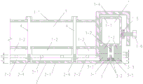
The invention provides a general mold for processing a prefabricated bottom plate of an assembled laminated slab, which consists of a top mold 1, a bottom mold 2, a bottom mold 3, connecting bolts 4 and a reinforcing mesh 5, and the structure of the general mold after installation is shown in figure 1.
The top die 1 comprises section steel 1-1, a limiting plate 1-2, an elastic edge sealing strip 1-3, an end connecting piece 1-4, a chuck 1-5 and a clamping bolt 1-6, and is shown in figures 2, 4, 8 and 10. Wherein the section steel 1-1 adopts a rectangular square pipe, and a hole site is reserved in the middle part for the connecting bolt 4, as shown in fig. 4 and 10; the limiting plates 1-2 are steel plates, are welded with the bottoms of the section steels 1-1, are disconnected at reserved hole positions of the connecting bolts 4 and are arranged in sections, as shown in the figures 2 and 10; the elastic edge banding strips 1-3 are made of flexible materials (such as rubber), are bonded with the bottom surface of the section steel 1-1 and are arranged in a full-length mode, as shown in figures 2 and 8, at the exposed part of the lower layer of steel bars 5-1, the elastic edge banding strips 1-3 are extruded by the steel bars and partially contract, as shown in figures 3 and 8, the rest parts are not extruded and still maintain the original shape, and after being attached to the elastic edge banding strips of the bottom die, the top die 1 can be ensured to be sealed with the bottom die 2 and the bottom die 3, as shown in figures 8 and 10; the end connecting piece 1-4 is bent by adopting a steel plate and is welded with the periphery of the end part of the section steel 1-1, as shown in figures 8 and 10; the clamping chuck 1-5 is combined with the clamping bolt 1-6, the clamping bolt 1-6 penetrates through the opening of the end connecting piece 1-4, and the clamping chuck 1-5 and the side surface of the top die 1 in the other direction can be tightly propped through the suspension clamping bolt 1-6, so that the effect of connecting and fixing the dies in the two directions is achieved.
The bottom die 2 is composed of a bottom plate 2-1, a limiting strip 2-2, an elastic edge sealing strip 2-3 and a screw cap 2-4, as shown in fig. 2, 4, 8 and 10. Wherein the bottom plate 2-1 is a steel plate, and the width of the bottom plate is the same as that of the section steel 1-1; the limiting strips 2-2 are steel strips, the number of the limiting strips is two, the limiting strips are welded with the bottom plate 2-1, and the sum A of the heights of the bottom plate 2-1 and the limiting strips 2-2 is the same as the thickness of the bottom concrete protective layer of the lower-layer steel bar 5-1; the elastic edge banding strips 2-3 are made of flexible materials (such as rubber) and are bonded with the bottom plate 2-1, as shown in figures 2 and 8, the elastic edge banding strips 2-3 are extruded by the steel bars to be locally contracted at the exposed parts of the lower layer of the steel bars 5-1, as shown in figures 3 and 8, the rest parts are not extruded and still maintain the original shape, and after being attached to the elastic edge banding strips 1-3, the top mold 1 and the bottom mold 2 can be ensured to be sealed, as shown in figure 8; the screw cap 2-4 is embedded into the bottom plate 2-1 and welded, and the limiting strip 2-2 is disconnected at the corresponding position, as shown in figures 4 and 10.
The bottom die 3 is composed of a bottom plate 3-1, a limiting strip 3-2, an elastic edge sealing strip 3-3, a screw cap 3-4 and a base plate 3-5, and is shown in fig. 5, 7, 9 and 11. Wherein, the three parts of the bottom plate 3-1, the limiting strips 3-2 and the screw caps 3-4 of the bottom die 3 and the three parts of the bottom plate 2-1, the limiting strips 2-2 and the screw caps 2-4 of the bottom die 2 are the same parts, and the parts can be replaced universally. The elastic edge banding strips 3-3 are made of flexible materials (such as rubber) and are bonded with the bottom plate 2-1, the thickness of the elastic edge banding strips is larger than that of the elastic edge banding strips 2-3, the difference value is the diameter D1 of the lower layer of steel bars 5-1, as shown in figures 5 and 9, the elastic edge banding strips 3-3 are extruded by the steel bars at the exposed parts of the upper layer of steel bars 5-2 and partially contract, as shown in figures 6 and 9, the rest parts are not extruded and still maintain the original shape, and after being bonded with the elastic edge banding strips 1-3, the top die 1 and the bottom die 3 can be ensured to be sealed, as shown in figure 9; the backing plate 3-5 is inserted into the gap between the limiting strips 3-2, the size of the upper edge exceeding the limiting strips 3-2 is the diameter D1 of the lower layer steel bar 5-1, and the position of the upper layer steel bar 5-2 is controlled.
The connecting bolt 4 is a compression connecting piece between the top die 1 and the bottom die 2 and between the bottom die 3 and is respectively connected and screwed with the screw caps 2-4 and the screw caps 3-4.
Wherein, the reinforcing mesh 5 consists of a lower layer reinforcing steel bar 5-1 and an upper layer reinforcing steel bar 5-2, the diameter of the lower layer reinforcing steel bar 5-1 is D1, and the diameter of the upper layer reinforcing steel bar is D2.
In conclusion, the top die 1 and the bottom die 2 are combined to be suitable for the side dies at two exposed sides of the lower layer steel bar 5-1; the top die 1 and the bottom die 3 are combined to be suitable for two side dies with exposed upper-layer steel bars 5-2, as shown in figure 1.
The installation process of the invention is as follows:
according to the size of the bottom plate of the laminated plate to be processed, a bottom die 2 and a bottom die 3 are respectively arranged on four sides of the laminated plate to be processed, a reinforcing mesh 5 is arranged on the four sides of the laminated plate, wherein the bottom die 2 is located at two ends of a lower layer of reinforcing steel bars 5-1, and the bottom die 3 is located at two ends of an upper layer of reinforcing steel bars 5-2.
The top die 1 is placed at the position of the four sides corresponding to the bottom die 2 and the bottom die 3, the top die 1 is connected with the bottom die 2 and the bottom die 3 in pairs through end connectors 1-4, chucks 1-5 and clamping bolts 1-6, and meanwhile, the connecting bolts 4 are installed to connect the top die 1 with the bottom die 2 and the bottom die 3. And after the size is accurately measured, the connecting bolt 4 and the clamping bolts 1-6 are locked, and the integral installation of the die is completed.
After the die is integrally installed, the lower layer of steel bars 5-1 are clamped by the limiting plates 1-2 and the limiting strips 2-2, and the distance from the bottom surfaces of the steel bars to the die table is equal to the thickness A of the concrete protective layer of the steel bars, as shown in figure 3; the upper layer of steel bars 5-2 are clamped by the limiting plates 1-2 and the backing plates 3-5, and the distance from the bottom surfaces of the steel bars to the die table is A + D1, as shown in FIG. 6; and pouring the bottom plate concrete of the laminated plate.
And after the bottom plate concrete of the laminated plate reaches the form removal strength, loosening the connecting bolts 4 and the clamping bolts 1-6, and removing the forms of all the parts.
The invention has the beneficial effects.
The invention has the advantages that the repeated utilization rate of the mould is high, the mould can be suitable for processing the prefabricated bottom plate of the assembled laminated slab with various reinforcing steel bar arrangement modes, the mould notch does not need to be arranged for each reinforcing steel bar, and the sealing strip does not need to be additionally arranged.
The reinforcement cage can be matched with reinforcement cages with different diameters only by adjusting the sizes of the elastic edge banding 3-3 and the backing plate 3-5, and the repeated utilization rate is high.
The invention can be suitable for processing prefabricated bottom plates of assembled laminated slabs with various plane sizes by adjusting the connecting position between the top moulds 1, and has high repeated utilization rate.
The top die 1, the bottom die 2 and the bottom die 3 are all of symmetrical structures, can be used on two sides, and are convenient to operate.
The bottom die 2 and the bottom die 3 have the same structure, can be interchanged for use only by replacing the elastic edge sealing strips 3-3, and the cushion plates 3-5 are movable accessories and can be flexibly placed.
Drawings
Fig. 1 is an overall installation view of the present invention.
Fig. 2 is an assembled cross section of the top die 1 and the bottom die 2.
Fig. 3 is a cross section of the exposed part of the assembled reinforcing steel bars of the top die 1 and the bottom die 2.
Fig. 4 is a cross-sectional view of the connecting part assembled by the top die 1 and the bottom die 2.
Fig. 5 is an assembled cross-sectional view of the top mold 1 and the bottom mold 3.
FIG. 6 is a cross-sectional view of the exposed portions of the reinforcing bars assembled on the top die 1 and the bottom die 3.
Fig. 7 is a cross-sectional view of the connecting member assembly of the top mold 1 and the bottom mold 3.
FIG. 8 is a longitudinal section of the elastic sealing strip assembled by the top mold 1 and the bottom mold 2.
FIG. 9 is a longitudinal sectional view of the limiting plate assembled with the top mold 1 and the bottom mold 2.
FIG. 10 is a longitudinal sectional view of the elastic sealing strip assembled on the top mold 1 and the bottom mold 3.
FIG. 11 is a longitudinal sectional view of the top mold 1 and the bottom mold 3 assembled with the limiting plate.
Reference numbers in the figures: the steel bar net is characterized in that 1 is a top die, 1-1 is section steel, 1-2 is a limiting plate, 1-3 is an elastic edge sealing strip, 1-4 is an end connecting piece, 1-5 is a chuck, 1-6 is a clamping bolt, 2 is a bottom die, 2-1 is a bottom plate, 2-2 is a limiting strip, 2-3 is an elastic edge sealing strip, 2-4 is a nut, 3 is a bottom die, 3-1 is a bottom plate, 3-2 is a limiting strip, 3-3 is an elastic edge sealing strip, 3-4 is a nut, 3-5 is a base plate, 4 is a connecting bolt, 5 is a steel bar net, 5-1 is a lower-layer steel bar, and 5-2 is an upper-layer steel bar.
Detailed Description
The invention is further described below by way of examples.
In the embodiment 1, the section steel 1-1 of the top die 1 adopts a hollow square tube of 80mmX60mm, the wall thickness is 6mm, the length is 4.2m, and round holes with the diameter of 14mm are formed in the center of the bottom surface of the top surface every 0.5m and are used for penetrating and connecting bolts 4; the limiting plate 1-2 is made of a steel plate with the width of 17mm and the thickness of 6mm in a segmented mode, each segment is 470mm in length, and the limiting plate is welded between the two bolt holes; the elastic edge banding 1-3 adopts two 21mmX21mm rubber strips, and the top surface of the elastic edge banding is glued with the section steel 1-1; the end connecting piece 1-4 is formed by bending a steel plate with the width of 80mm and the thickness of 12mm, one side of the end connecting piece is welded with the section steel 1-1, the middle part of the other side of the end connecting piece is provided with a threaded hole, M16 internal threads and a chuck 1-5 are processed by a steel plate with the thickness of 6mm, the diameter of the steel plate is 50mm, and a clamping bolt 1-6 is an M16 bolt.
The bottom plate 2-1 of the bottom die 2 is a steel plate with the width of 60mm and the thickness of 8 mm; the limiting strips 2-2 are two steel plates with the thickness of 6mm, the width of the limiting strips is 7mm, the limiting strips are manufactured in a segmented mode, the length of each segment is 470mm, the distance between the two steel plates is 6.5mm, and the outer sides of the limiting strips are welded with the bottom plate 2-1; the elastic edge sealing strip 2-3 adopts two 21mmX11mm rubber strips, and the bottom surface of the elastic edge sealing strip is glued with the bottom plate 2-1; the screw caps 2-4 are M12 screw caps, have a thickness of 15mm, are welded on the axial line of the base plate 2-1 at a spacing of 0.5M, are aligned with the openings of the section steel 1-1, and are embedded in the screw caps at the corresponding positions of the base plate and are welded.
The bottom plate 3-1, the limiting strips 3-2 and the screw caps 3-4 of the bottom die 3 are all the same as the bottom plate 2-1, the limiting strips 2-2 and the screw caps 2-4 of the bottom die 2; the elastic edge banding 3-3 adopts two 21mmX19mm rubber strips, and the bottom surface is glued with the bottom plate 2-1; the backing plate 3-5 is a steel plate with the thickness of 6mm, the width of the backing plate is 15mm, the backing plate is manufactured in a segmented mode, the length of each segment is 470mm, and the backing plate is inserted into a notch between the two limiting strips 3-2 during installation.
The connecting bolt 4 is an M12 bolt, is 125mm long, is connected and screwed with the screw caps 2-4 and 3-4 of the bottom plate 2 and the bottom plate 3, and tightly presses the top die 1, the bottom die 2 and the bottom die 3.
The lower layer steel bars 5-1 and the upper layer steel bars 5-2 of the steel bar mesh 5 are steel bars with the diameter of 8 mm;
the embodiment is suitable for processing the bottom plate of the prefabricated composite slab with the length and width of not more than 4m, and only needs to adjust the length of the die when used for processing plates with other sizes; all the parts can be connected by welding, sticking and bolts; referring to fig. 1 to 11, the technical personnel for processing and installation in the technical field can implement the method smoothly.
The above description is only one embodiment of the present invention, and the protection scope of the present invention is not limited thereto, and any modification to the technical solution and concept of the present invention should be covered within the protection scope of the present invention.
Claims (7)
1. The utility model provides a general mould of prefabricated bottom plate processing of assembled superimposed sheet, comprises top mould (1), die block (2), die block (3), connecting bolt (4), and wherein top mould and die block form by steel and elastic material combination, and the fixed mode of installation is threaded connection between each part, and the mould after the installation is accomplished inlays reinforcing bar net (5) in the centre, and its characteristic lies in: after the top die and the bottom die are combined, the exposed reinforcing steel bars of the reinforcing steel bar net (5) are clamped to position the reinforcing steel bar net, and the elastic edge sealing strips are tightly attached.
2. The general mold for processing the prefabricated bottom plate of the fabricated laminate slab as claimed in claim 1, wherein the elastic edge banding strips are arranged in a through manner, after the top mold and the bottom mold are tightly pressed by the connecting bolts (4), the elastic edge banding strips can adaptively block gaps between exposed steel bars of the steel bar mesh, no grout leakage gap exists in the whole length of the mold when concrete is poured, and the mold is restored to an initial state after being dismantled and can be reused.
3. The general mold for processing the prefabricated bottom plate of the fabricated laminate slab of claim 1, wherein the limiting plates of the top mold, the limiting strips of the bottom mold and the backing plate are used for limiting the exposed steel bars of the steel bar mesh, so as to ensure accurate positioning of the steel bars in the laminate slab.
4. The universal mold for processing prefabricated base plates of fabricated laminate according to claim 1, wherein the position of the upper mesh reinforcement can be adjusted by using different sizes of the base plates (3-5), and the universal mold is suitable for mesh reinforcements consisting of reinforcements with different diameters.
5. The general mold for processing the prefabricated bottom plate of the fabricated laminate slab as claimed in claim 1, wherein the four-sided top mold can be fixedly connected to any position of the middle of the adjacent top mold through an end connector to form a rectangular mold with adjustable size, and the mold can be repeatedly used after being disassembled.
6. The general mold for processing the prefabricated bottom plate of the fabricated laminate as claimed in claim 1, wherein the top mold and the bottom mold are both of a left-right symmetrical structure, and both side surfaces thereof can be used as inner sides of the mold.
7. The universal mold for processing the prefabricated bottom plate of the fabricated composite slab as claimed in claim 1, wherein the bottom mold (2) and the bottom mold (3) can be replaced by each other after replacing the elastic edge sealing strips.
Priority Applications (1)
| Application Number | Priority Date | Filing Date | Title |
|---|---|---|---|
| CN201910377647.9A CN111906902A (en) | 2019-05-08 | 2019-05-08 | General mould of prefabricated bottom plate processing of assembled superimposed sheet |
Applications Claiming Priority (1)
| Application Number | Priority Date | Filing Date | Title |
|---|---|---|---|
| CN201910377647.9A CN111906902A (en) | 2019-05-08 | 2019-05-08 | General mould of prefabricated bottom plate processing of assembled superimposed sheet |
Publications (1)
| Publication Number | Publication Date |
|---|---|
| CN111906902A true CN111906902A (en) | 2020-11-10 |
Family
ID=73241701
Family Applications (1)
| Application Number | Title | Priority Date | Filing Date |
|---|---|---|---|
| CN201910377647.9A Pending CN111906902A (en) | 2019-05-08 | 2019-05-08 | General mould of prefabricated bottom plate processing of assembled superimposed sheet |
Country Status (1)
| Country | Link |
|---|---|
| CN (1) | CN111906902A (en) |
Cited By (2)
| Publication number | Priority date | Publication date | Assignee | Title |
|---|---|---|---|---|
| CN112917649A (en) * | 2021-01-29 | 2021-06-08 | 中建科技(湖州)有限公司 | Universal superimposed plate die |
| CN113070984A (en) * | 2021-03-23 | 2021-07-06 | 山东泰迅装配式建筑科技有限公司 | Universal laminated plate mold and using method |
-
2019
- 2019-05-08 CN CN201910377647.9A patent/CN111906902A/en active Pending
Cited By (2)
| Publication number | Priority date | Publication date | Assignee | Title |
|---|---|---|---|---|
| CN112917649A (en) * | 2021-01-29 | 2021-06-08 | 中建科技(湖州)有限公司 | Universal superimposed plate die |
| CN113070984A (en) * | 2021-03-23 | 2021-07-06 | 山东泰迅装配式建筑科技有限公司 | Universal laminated plate mold and using method |
Similar Documents
| Publication | Publication Date | Title |
|---|---|---|
| CN210679083U (en) | General mould of prefabricated bottom plate processing of assembled superimposed sheet | |
| CN110344340B (en) | Reinforcing device for reinforcing pier by cofferdam-free underwater cross section increasing method and construction method thereof | |
| CN111906902A (en) | General mould of prefabricated bottom plate processing of assembled superimposed sheet | |
| CN209811582U (en) | Large diameter pipeline aligning deviation processing positioning device | |
| CN210421925U (en) | Positioning and embedding device for water stop joint of building | |
| CN210090177U (en) | Laboratory is with old and new concrete split and draw shear test multifunctional mold | |
| CN109162371B (en) | Fixing structure of externally-adhered rubber water stop and construction method thereof | |
| CN109518960B (en) | Shaping mold capable of realizing turnover of reserved hole of cast-in-situ roof and construction method of shaping mold | |
| CN111042188A (en) | Supporting-free template for reserved bolt holes of roughing mill body and construction method | |
| CN215671022U (en) | Pre-embedded type mounting device for aluminum alloy template | |
| CN214739890U (en) | Steel form for concrete constructional column construction | |
| CN211547390U (en) | Assembled pier stud template convenient to dismantle | |
| CN211849566U (en) | Roughing mill body reserved bolt hole support-free template | |
| CN214246617U (en) | Unilateral mould bearing structure is striden to height | |
| CN211194334U (en) | Forming die for grouting sleeve connection prefabricated shear wall | |
| CN209737910U (en) | Combined die for producing prefabricated parts | |
| CN211473410U (en) | Template assembling structure of vertical structural member free of hole opening | |
| CN218061432U (en) | A anchor clamps for reinforcing concrete column template with adjustable | |
| CN218815189U (en) | Combined side die base plate with length adjusting structure | |
| CN111502263A (en) | Cast-in-place crossbeam component of prefabricated building leak protection thick liquid pours mould | |
| CN211228922U (en) | Pre-buried channel pressure formula mounting structure | |
| CN212957629U (en) | Slurry leakage prevention column mould for residential construction | |
| CN217840881U (en) | Construction device for penetrating roof pipeline sleeve and reinforced concrete member | |
| CN216999374U (en) | Quick connector for concrete embedded pull rod | |
| CN211548796U (en) | Stagnant water bolt assembly |
Legal Events
| Date | Code | Title | Description |
|---|---|---|---|
| PB01 | Publication | ||
| PB01 | Publication | ||
| WD01 | Invention patent application deemed withdrawn after publication |
Application publication date: 20201110 |
|
| WD01 | Invention patent application deemed withdrawn after publication |