CN111877044B - Waste paper pulp recycling treatment device - Google Patents
Waste paper pulp recycling treatment device Download PDFInfo
- Publication number
- CN111877044B CN111877044B CN202010661606.5A CN202010661606A CN111877044B CN 111877044 B CN111877044 B CN 111877044B CN 202010661606 A CN202010661606 A CN 202010661606A CN 111877044 B CN111877044 B CN 111877044B
- Authority
- CN
- China
- Prior art keywords
- cabin
- welded
- paper pulp
- plate
- pump
- Prior art date
- Legal status (The legal status is an assumption and is not a legal conclusion. Google has not performed a legal analysis and makes no representation as to the accuracy of the status listed.)
- Active
Links
Images


Classifications
-
- D—TEXTILES; PAPER
- D21—PAPER-MAKING; PRODUCTION OF CELLULOSE
- D21F—PAPER-MAKING MACHINES; METHODS OF PRODUCING PAPER THEREON
- D21F1/00—Wet end of machines for making continuous webs of paper
- D21F1/66—Pulp catching, de-watering, or recovering; Re-use of pulp-water
-
- Y—GENERAL TAGGING OF NEW TECHNOLOGICAL DEVELOPMENTS; GENERAL TAGGING OF CROSS-SECTIONAL TECHNOLOGIES SPANNING OVER SEVERAL SECTIONS OF THE IPC; TECHNICAL SUBJECTS COVERED BY FORMER USPC CROSS-REFERENCE ART COLLECTIONS [XRACs] AND DIGESTS
- Y02—TECHNOLOGIES OR APPLICATIONS FOR MITIGATION OR ADAPTATION AGAINST CLIMATE CHANGE
- Y02W—CLIMATE CHANGE MITIGATION TECHNOLOGIES RELATED TO WASTEWATER TREATMENT OR WASTE MANAGEMENT
- Y02W30/00—Technologies for solid waste management
- Y02W30/50—Reuse, recycling or recovery technologies
- Y02W30/64—Paper recycling
Abstract
The invention relates to a waste paper pulp recycling treatment device, which comprises a large bottom plate, a material returning frame, a supporting tube, a pressure bearing disc and an elastic supporting mechanism, wherein the material returning frame is arranged on the large bottom plate; the utility model discloses a paper pulp recovery device, including big bottom plate, water collection tank, inner chamber, pump, the top surface of big bottom plate is installed pump, album liquid cabin and stay tube, the pump is located the right side of album liquid cabin, the feed liquor pipe of pump stretches into in the collection liquid cabin, the top surface welding of stay tube has paper pulp to connect the cabin, the fluid-discharge tube of pump upwards stretches into paper pulp and connects in the cabin, the inner chamber welds on the top surface of big bottom plate, the inner chamber is located in the inner chamber of collection liquid cabin, the design has the pump of retrieving the feed liquid, can retrieve the paper pulp after the outer paper stripping in receiving the cabin again, makes it circulate once more and compress the system cake, makes paper pulp recycle ratio improve once more, to sum up, can find out, this paper pulp waste material is collection device once more, combines together four functions of paper pulp separation, pressure cake, material returned, material, the material of getting for the device has characteristics rational in infrastructure, convenient to operate, compact structure, practicality are strong.
Description
Technical Field
The invention relates to the technical field of paper pulp recovery, in particular to a waste paper pulp recycling treatment device which is also used for environment-friendly treatment of all waste fiber-containing pulp.
Background
Paper pulp (pulp) is a fibrous substance prepared by using plant fibers as raw materials and adopting different processing methods. Mechanical pulp, chemical pulp and chemimechanical pulp can be classified according to the processing method; the fiber raw materials can also be divided into wood pulp, straw pulp, hemp pulp, reed pulp, cane pulp, bamboo pulp, rag pulp and the like according to the used fiber raw materials. And can be divided into refined pulp, bleached pulp, unbleached pulp, high-yield pulp, semi-chemical pulp and the like according to different purities. Are commonly used in the manufacture of paper and paperboard. Refined pulp is often used as a raw material for producing cellulose derivatives such as cellulose esters and cellulose ethers, in addition to specialty paper.
In both the mechanical industry and the chemical industry, a large amount of fiber-containing pulp such as paper pulp is generated in the production process, and if the paper pulp is directly discarded as waste, the waste is generated, and the paper pulp cannot be utilized to the maximum extent, so that the waste is caused. Meanwhile, the direct discharge of the pulp along with water also causes great difficulty in subsequent wastewater treatment, causes problems of winding, clogging and the like of water treatment equipment, increases and decreases the environmental treatment cost, and causes serious pollution to the surrounding environment due to the direct discharge. Rational solution and treatment are urgently needed.
Disclosure of Invention
Aiming at the existing problems, the invention aims to provide a waste paper pulp recycling treatment device, which adopts a compression type disc cabin mechanism to receive paper pulp discharged in the industrial production process and recycle the paper pulp after pressing the paper pulp into cakes, so as to realize water and material separation, reduce the environmental pollution caused by the direct discharge of the paper pulp and the cakes, recycle valuable fiber materials and have the beneficial characteristic of environmental protection and reutilization.
In order to achieve the purpose, the invention provides the following technical scheme:
a waste paper pulp recycling treatment device comprises a large bottom plate, a water lifting pump, a liquid collecting cabin, an inner cabin, a material taking mechanism, a material returning frame, a supporting tube, a pressure bearing disc and a spring support mechanism; a water pump, a liquid collecting cabin and a supporting pipe are arranged on the top surface of the large bottom plate, the water pump is positioned on the right side of the liquid collecting cabin, a liquid inlet pipe of the water pump extends into the liquid collecting cabin, a paper pulp receiving cabin is welded on the top surface of the supporting pipe,
the left side of the inner cabin is welded with a guide block, the left end face of the guide block is provided with an electric cylinder, an action rod of the electric cylinder extends downwards, a moving rod is arranged at the bottom end of the action rod, the moving rod penetrates through the guide block in a vertically upward mode after being turned right, the right side of the moving rod is vertically bent downwards, an extrusion disc is arranged at the bottom end of a vertical section, the extrusion disc is positioned at the top of the pressure bearing disc, the bottom of the pressure bearing disc is provided with dense hemp filtering holes, and three material returning jacks are uniformly distributed and formed in the extrusion disc;
the material returning frame is welded on the top surface of the guide block, the top end of the material returning frame is horizontally bent towards the right, a circular material returning plate is welded on the horizontal bent section, and three cylindrical material returning rods are uniformly welded on the bottom surface of the material returning plate; the material returning rod is opposite to the material returning jack.
Preferably, the material taking mechanism comprises a welding frame, a carrying rod, a guide pillar, a return spring, a compression cylinder and a hanging plate, the guide pillar is welded on the front surface of the inner cabin, the return spring is sleeved on the guide pillar, the welding frame is a U-shaped bent pipe with a row of carrying rods welded on the top surface, the compression cylinder sleeved on the guide pillar in a sliding mode is welded at the inner end of the front portion of the welding frame, the compression cylinder abuts against the end face of the return spring, the hanging plate is welded on the bottom surface of the front side of the welding frame, and two left and right insertion holes for enabling the left end and the right end of the U-shaped welding frame to extend into and guide are formed in the top of the front side of the inner cabin.
Preferably, a liquid discharge pipe of the water pump extends upwards into the pulp receiving chamber, the inner chamber is welded on the top surface of the large bottom plate, the inner chamber is located in an inner cavity of the liquid collecting chamber, the pulp receiving chamber is welded on the right side of the top of the inner chamber, a wall clamping cavity is formed between the inner chamber and the liquid collecting chamber, a water inlet of the liquid inlet pipe is located in the wall clamping cavity, the bottom of the inner chamber is provided with a circle of liquid discharge holes, the liquid discharge holes are communicated with the wall clamping cavity, a circle of elastic support mechanism is welded in the inner cavity of the inner chamber, a pressure bearing disc is arranged at the top of the elastic support mechanism, and a feed inlet communicated with the pulp receiving chamber is formed in the right side of the pressure bearing disc.
Preferably, the extrusion disc is of a circular cavity structure, a circle of material inserting rods are welded on the bottom surface of the circular cavity, and the material inserting rods are conical rods with spiral textures arranged outside; the height of the extrusion disc is half of the height of the inner cavity of the pressure bearing disc.
Preferably, a steel wire rope is hung on the hanging plate, and a transition wheel is installed at the top of the front side of the liquid collecting cabin.
Preferably, the front end of the welding frame is at a certain distance from the front end of the transition wheel, and the steel wire rope continues to extend downwards after passing through the transition wheel.
Preferably, a pedal rod is installed at the bottom end of the steel wire rope, and a limiting plate used for limiting the bottom of the transition wheel is welded at the middle section of the steel wire rope.
Preferably, the elastic supporting mechanism comprises a collecting pipe welded on the bottom surface of the inner cabin, a spring inserted in the collecting pipe, and a pressing pipe in sliding fit with the collecting pipe, and the bottom surface of the pressure bearing disc is elastically supported on the pressing pipe.
Preferably, the carrying rod is a U-shaped bent rod, and they are welded on the top surface of the welding frame in a clearance shape.
Preferably, the material returning rod is inserted downwards into the material returning insertion hole and extends downwards into the circular cavity of the extrusion disc from the material returning insertion hole.
Compared with the prior art, the invention has the following beneficial effects:
(1) the method comprises the steps that firstly, a paper pulp collecting mechanism consisting of a receiving cabin and a liquid collecting cabin and a pressure plate mechanism positioned at the top of the liquid collecting cabin are used, paper pulp received through the receiving cabin is injected into the liquid collecting cabin, feed liquid in the paper pulp is extruded downwards under the counter-pressure action of the pressure plate mechanism, then a compressed paper cake can be obtained, and finally waste paper pulp can be recycled when discharged outwards.
(2) Secondly, in order to improve the structural rationality, the pressed paper cakes are convenient to take, the material returning frame is arranged at the top of the paper cake pressing mechanism, the paper cakes obtained by the pressing plate mechanism can be upwards extracted and then downwards discharged through the material returning frame, the material taking mechanism is arranged on the front side of the paper cake pressing mechanism, and when the material taking mechanism is stepped by feet, the material taking mechanism moves backwards, so that the paper cakes falling out of the pressing plate mechanism can be quickly taken out forwards, and the operation is convenient.
(3) And the design has the lift pump of retrieving the feed liquid, can retrieve the paper pulp after the outer paper that takes off again and receive the cabin in, makes its recycling cycle again and compress the system cake, makes paper pulp recycle rate improve once more to sum up, can find out, this paper pulp waste material is collection device once more, and four functions with paper pulp separation, pressure cake, material returned, material taking are integrated for the device has rational in infrastructure, be convenient for operation, compact structure, characteristics that the practicality is strong.
Drawings
FIG. 1 is a schematic structural view of the present invention;
FIG. 2 is a schematic front plan view of the present invention taken from FIG. 1;
FIG. 3 is a schematic view of the plane structure of section B taken from FIG. 4;
FIG. 4 is a top plan view of the present invention;
FIG. 5 is a schematic view of the plane structure of section A taken from FIG. 4;
FIG. 6 is a schematic view of the liquid collection tank and the inner tank of the present invention partially cut away together to view the internal structures;
FIG. 7 is a schematic view of the structure of the liquid collecting tank of the present invention after the mechanisms are moved outwards;
FIG. 8 is a bottom elevation view of the bottom of the crush disk with the inner chamber cut away in accordance with the present invention;
FIG. 9 is a schematic view showing the connection and structure of the spring supporting mechanism and the bearing plate on the top of the spring supporting mechanism;
FIG. 10 is a bottom perspective view of the present invention from FIG. 9;
FIG. 11 is a schematic view showing the structure of the rotary plunger of the present invention.
Description of the main reference numerals:
1. a large bottom plate; 2. receiving paper pulp; 3. a lift pump; 4. a liquid collection chamber; 401. a transition wheel; 5. an inner chamber; 501. a jack; 502. a drain hole; 6. a material taking mechanism; 601. welding a frame; 602. a carrier bar; 603. a guide post; 604. a return spring; 605. a compression cylinder; 606. hanging the plate; 7. a wire rope; 701. a limiting plate; 702. treading the rod; 8. a liquid inlet pipe; 9. a liquid discharge pipe; 10. a guide block; 11. an electric cylinder; 1101. a travel bar; 1102. an extrusion disc; 1103. inserting a material rod; 1104. a material returning jack; 12. a material returning frame; 1201. a material returning plate; 1202. a material returning rod; 13. supporting a tube; 14. a pressure bearing disc; 1401. a feed inlet; 1402. a filtration pore; 15. a spring support mechanism; 1501. pressing a pipe; 1502. collecting the pipe; 1503. a spring.
Detailed Description
The technical solutions of the present invention will be described in detail and fully with reference to the accompanying drawings, and it should be understood that the described embodiments are only some embodiments, but not all embodiments, of the present invention. All other embodiments, which can be derived by a person skilled in the art from the embodiments given herein without making any creative effort, shall fall within the protection scope of the present invention.
In the description of the present invention, it should be noted that the orientations or positional relationships indicated as the terms "center", "upper", "lower", "left", "right", "vertical", "horizontal", "inner", "outer", etc., appear based on the orientations or positional relationships shown in the drawings only for the convenience of describing the present invention and simplifying the description, but not for indicating or implying that the referred devices or elements must have a specific orientation, be constructed and operated in a specific orientation, and thus should not be construed as limiting the invention.
In the description of the present invention, it should be noted that, unless otherwise explicitly stated or limited, the terms "mounted," "connected," and "connected" should be interpreted broadly, e.g., as being fixed or detachable or integrally connected; can be mechanically or electrically connected; they may be connected directly or indirectly through intervening media, or they may be interconnected between two elements. The specific meaning of the above terms in the present application can be understood in a specific case to those skilled in the art.
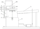
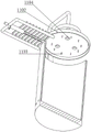
Referring to the attached drawings 1-11, the waste paper pulp recycling and treating device comprises a large bottom plate 1, a lifting pump 3, a liquid collecting cabin 4, an inner cabin 5, a material taking mechanism 6, a material returning frame 12, a supporting tube 13, a pressure bearing disc 14 and an elastic supporting mechanism 15; the top surface of the large bottom plate 1 is provided with a lift pump 3, a liquid collecting cabin 4 and a supporting pipe 13, the lift pump 3 is positioned at the right side of the liquid collecting cabin 4, a liquid inlet pipe 8 of the lift pump 3 extends into the liquid collecting cabin 4, and a valve type branch external discharge pipe is arranged on the liquid inlet pipe 8, as can be seen in figure 1, a paper pulp receiving cabin 2 is welded on the top surface of the supporting pipe 13, a liquid discharge pipe 9 of the lift pump 3 extends upwards into the paper pulp receiving cabin 2, when in actual use, the right side of the paper pulp receiving cabin 2 is connected to industrial equipment, when the industrial equipment works, the produced paper pulp enters the paper pulp receiving cabin 2 and enters the liquid collecting cabin 4 from the paper pulp receiving cabin 2, after being processed by various mechanisms (the mechanisms are described in detail in the following description) in the liquid collecting cabin 4, the liquid inlet pipe 8 enters the lift pump 3, if the depth of the discharged pulp is larger, the pulp is guided upwards into the paper pulp receiving cabin 2 by the liquid discharge pipe 9 again, the pulp flows back to the liquid collecting cabin 4 again, on the contrary, if the depth of the discharged pulp is shallow, a valve on a branch pipe on the liquid inlet pipe 8 is directly opened, the pulp flows into the external existing sewage treatment equipment, the inner cabin 5 is welded on the top surface of the large bottom plate 1, the inner cabin 5 is positioned in the inner cavity of the liquid collecting cabin 4, the pulp actually enters the inner cabin 5 in the liquid collecting cabin 4, therefore, the pulp receiving cabin 2 is welded on the right side of the top of the inner cabin 5, a wall clamping cavity is formed between the inner cabin 5 and the liquid collecting cabin 4, a water inlet of the liquid inlet pipe 8 is positioned in the wall clamping cavity, the bottom of the inner cabin 5 is provided with a circle of liquid outlet holes 502, the liquid outlet holes 502 are communicated with the wall clamping cavity, the pulp entering the inner cabin 5 reaches the bottom and enters the wall clamping cavity through the liquid outlet holes 502, finally enters the liquid inlet pipe 8 through the wall clamping cavity, and is pumped into the water pump 3 through the liquid inlet pipe 8, a circle of elastic support mechanism 15 is welded in the inner cavity of the inner cabin 5, the top of the elastic supporting mechanism 15 is provided with a pressure-bearing disc 14, the right side of the pressure-bearing disc 14 is provided with a feed inlet 1401 communicated with the pulp receiving chamber 2, a circle of elastic supporting mechanism positioned in the inner chamber 5 is formed, the pressure-bearing disc 14 is positioned on the elastic supporting mechanisms 15, the pressure-bearing disc 14 is used for receiving and taking the pulp entering the inner chamber 5, the pulp flowing into the liquid collecting chamber 4 firstly enters the pressure-bearing disc 14, as shown in fig. 5, 9 and 10, dense hemp filtering holes 1402 are formed at the bottom of the pressure-bearing disc 14, and the filtering holes 1402 are fine holes with a hole diameter of zero three millimeters, so that the pulp entering the pressure-bearing disc 14 is filtered, it will collect the paper material in the pulp again, while the filtered pulp water will pass through the filter holes 1402 into the inner chamber 5 at the bottom, then enters the cavity between the inner chamber 5 and the liquid collecting chamber 4 through a liquid discharging hole 502 arranged at the bottom of the inner chamber 5, and finally the filtered pulp water is extracted and treated by the water lifting pump 3.
As shown in fig. 2 and 6, a guide block 10 is welded on the left side of the inner chamber 5, an electric cylinder 11 is installed on the left end face of the guide block 10, and an action rod of the electric cylinder 11 extends downwards to avoid the material which is directly driven by the upward extension from falling and being stuck. And a moving rod 1101 is installed at the bottom end of the action rod, the moving rod 1101 is vertically upwards penetrated in the guide block 10 after turning right, the right side of the moving rod 1101 is downwards and vertically bent, and a pressing disc 1102 is installed at the bottom end of the vertical section, the pressing disc 1102 is right positioned at the top of the pressure bearing disc 14, after the electric cylinder 11 is electrified, the electrification principle of the electric cylinder 11 and a controller applied in cooperation therewith are the prior art, which is a general technology, and not otherwise mentioned, after the electrification control, the action rod can be driven to move up and down along with the moving rod 1101, such as is common on the existing oil press), the pressing disc 1102 is driven to move downwards by the moving rod 1101, the pressing disc 1102 slowly falls into the pressure bearing disc 14, paper obtained by filtering pulp in the pressure bearing disc 14 is pressed into cakes, and during the process, downward dropping pulp water is generated, and the pulp also falls into the inner chamber 5 through the filtering holes 1402, the cake-shaped compressed paper is collected between the pressure bearing disc 14 and the extrusion disc 1102, and since the extrusion disc 1102 has a circular cavity structure, a circle of material inserting rods 1103 is welded on the bottom surface of the circular cavity, that is, the upper top surface of fig. 8, and the material inserting rods 1103 are conical insertion rods with spiral textures as shown in fig. 11, when the moving rod 1101 on the electric cylinder 11 moves upwards again in the opposite direction, the paper cake obtained in the pressure bearing disc 14 is lifted upwards along with the extrusion disc 1102 by the inserted material inserting rods 1103.
As shown in fig. 1 and 8, three material returning insertion holes 1104 for making the paper cake fall downwards from the bottom cavity of the pressing plate 1102 are uniformly distributed on the pressing plate, and in order to achieve the function, as shown in fig. 1, 2 and 6, the material returning frame 12 is welded on the top surface of the guide block 10, the top end of the material returning frame 12 bends towards the right horizontally, a circular material returning plate 1201 is welded on the horizontal bending section, and three cylindrical material returning rods 1202 are uniformly welded on the bottom surface of the material returning plate 1201, so that when the pressing plate 1102 carries the paper cake to separate from the pressure bearing plate 14 and continues to move upwards, the material returning rods 1202 on the top are introduced through the material returning insertion holes 1104, so that the paper cake in the bottom cavity of the pressing plate 1102 is inserted downwards, and the obtained paper cake falls and is collected.
The material taking mechanism 6 for collecting the dropped paper in an insertion manner comprises a welding frame 601, a carrying rod 602, a guide post 603, a return spring 604, a compression cylinder 605 and a hanging plate 606, wherein the guide post 603 is welded on the front surface of the inner chamber 5, the return spring 604 is sleeved on the guide post 603, the welding frame 601 is a U-shaped bent pipe with a row of carrying rods 602 welded on the top surface, the compression cylinder 605 slidably sleeved on the guide post 603 is welded at the inner end of the front part of the welding frame, the hanging plate 606 is welded on the bottom surface of the front side of the welding frame 601, so the welding frame 601 is pushed towards the inner chamber 5 by hand pressing, the return spring 604 is stably guided by the guide post 603 during moving, the return spring 604 is compressed after the operation, the top of the front side of the inner chamber 5 is provided with a left insertion hole 501 and a right insertion hole for enabling the left end and the right end of the U-shaped welding frame 601 to extend into and guide, paper cakes in the bottom cavity of the pressing plate 1102 do not fall, a front side worker pushes the U-shaped welding frame 601 forwards, the U-shaped welding frame 601 enters the top of the inner chamber 5 along the insertion hole 501, the paper cakes falling from the bottom cavity of the extrusion disc 1102 just fall on the material taking mechanism 6, the material taking mechanism 6 losing the pressing effect returns forwards again under the influence of the return spring 604, and the paper cakes are taken out together.
Specifically, the height dimension of the extrusion disc 1102 is half of the height dimension of the inner cavity of the pressure bearing disc 14, the extrusion disc 1102 is just fallen into the pressure bearing disc 14 after moving downwards and forms an extrusion effect with the pressure bearing disc 14, so that paper materials filtered and intercepted in the pressure bearing disc 14 are compressed to form cakes, the extrusion disc 1102 is convenient to reset upwards after the cakes are formed, and the structure is more reasonable.
Specifically, as shown in fig. 1 and 3, a steel wire rope 7 is hung and pulled on a hanging plate 606, a transition wheel 401 is installed at the top of the front side of the liquid collecting cabin 4, and the steel wire rope 7 continuously extends downwards after passing through the transition wheel 401 due to the fact that the front end of a welding frame 601 is one meter and five distances away from the front end of the transition wheel 401, so that the steel wire rope 7 continuously pulled downwards moves backwards with the welding frame 601 under the guiding effect of the transition wheel 401, and finally the welding frame 601 reaches the top of the inner cabin 5.
Specifically, as shown in fig. 1, the bottom end of the steel wire rope 7 is provided with the pedal rod 702, the pedal rod 702 is a rectangular frame and can clamp and place the foot of the human body, and the middle section of the steel wire rope 7 is welded with the limiting plate 701 for limiting the bottom of the transition wheel 401, so that the steel wire rope 7 is in a foot-operated type pulling-down action, the moving mode of the welding frame 601 reaching the top of the inner cabin 5 is in a foot-operated type, the operation is convenient, and the humanized structure design is reasonable. The operation process is; the treading rod 702 is treaded, the free end of the steel wire rope 7 is continuously pulled downwards under the guidance of the transition wheel 401, then the welding frame 601 moves towards the top of the inner cabin 5 through the hanging plate 606, and the welding frame 601 pushed to the top of the inner cabin 5 is right opposite to the bottom of the extrusion disc 1102, so that a material receiving effect is formed (a material receiving mode is described in detail in the working principle below).
Specifically, as shown in fig. 6, 9 and 10, the elastic supporting mechanism 15 includes a receiving tube 1502 welded to the bottom surface of the inner chamber 5, a spring 1503 inserted into the receiving tube 1502, and a pressing tube 1501 slidably fitted into the receiving tube 1502, and the bottom surface of the pressure-bearing disc 14 is elastically supported on the pressing tube 1501, so that it can be seen that the bottom of the pressure-bearing disc 14 for filtering pulp has elastic properties, and therefore, when the pressing disc 1102 presses the top cavity of the pressure-bearing disc 14 and continues to press downward, the pressure-bearing disc 14 will also move downward, so that the pressed paper cake between them is slowly molded in a manner with certain buffering properties, thereby effectively preventing the pressing disc 1102 from pressing downward too much, which results in that the pressing disc and the paper cake in the pressure-bearing disc 14 are completely flattened without thickness or crushed, thereby affecting the discharge of the paper cake, and improving the structural rationality of the pressure-bearing disc 14.
Specifically, as shown in fig. 1, the carrying rod 602 is a U-shaped bent rod, which is welded on the top surface of the welding frame 601 in a gap shape, so that if the bottom of the paper cake falling on the carrying rod 602 still contains moisture, the moisture can pass through between the carrying rods 602 to achieve the purpose of controlling water.
Specifically, the material returning rod 1202 is inserted downward into the material returning insertion hole 1104 and extends downward into the circular cavity of the pressing plate 1102 from the material returning insertion hole 1104, that is, after the pressing plate 1102 is reset upward, the material returning rod 1202 will extend into the pressing plate 1102 through the material returning insertion hole 1104, and the paper cake lifted upward through the material inserting rod 1103 in the bottom cavity of the pressing plate 1102 is just inserted downward.
The working principle is as follows: in practical use, the device is located at one side of an industrial device, paper making equipment or other existing equipment which can form paper pulp is discharged into a paper pulp receiving chamber 2 by using a pulp discharge pipe, the paper pulp enters a pressure bearing disc 14 from a feeding hole 1401, after being filtered by a filtering hole 1402 in the pressure bearing disc 14, the paper pulp is intercepted in the pressure bearing disc 14, pulp water passes through the filtering hole 1402 and falls into an inner chamber 5 at the bottom side, finally enters a liquid collecting chamber 4 at the outer side from a liquid discharge hole 502 formed at the bottom of the inner chamber 5, is pumped into a water lifting pump 3 by a liquid inlet pipe 8, if the pulp water is not required to be reused, the pulp water is directly discharged outwards by a branch pipe (seen in figure 1, the prior art of the branch pipe fitting is not indicated by a serial number), if the pulp water needs to flow back to the paper pulp receiving chamber 2 again, a valve on the branch pipe is closed, the slurry is guided upward into the pulp receiving chamber 2 again by the drainage pipe 9, a large amount of paper is held up in the inner cavity of the pressure bearing plate 14 after a while, at this time, the electric cylinder 11 is energized to operate, the actuating rod thereof carries the moving rod 1101 to move downward, and at the same time, the moving rod 1101 carries the extrusion plate 1102 to move downward, the extrusion plate 1102 slowly falls down into the pressure bearing plate 14, the paper held up by the filtered slurry in the pressure bearing plate 14 is extruded into a cake, and the pressure bearing plate 14 is buffered downward by the bottom support mechanism 15 during the extrusion, so that the excessive downward pressure of the extrusion plate 1102 is effectively prevented, which causes the cake to be completely pressed with the paper in the pressure bearing plate 14 without thickness or to be extruded into a crumbled shape, and during this process, the downward dropping slurry water is generated by the paper squeezing in the pressure bearing plate 14, and the slurry water also falls into the inner chamber 5 through the filtering holes 1402, under the influence of the external existing electric control technology, the electric cylinder 11 can make the action rod bring the moving rod 1101 to move upwards in a resetting manner, meanwhile, the extrusion disc 1102 at the bottom of the moving rod 1101 moves upwards, the pressure bearing disc 14 slowly losing the extrusion effect moves upwards again in a resetting manner under the elastic resetting action of the elastic support mechanism 15, finally, the pressure bearing disc 14 resets to the original position again, the paper cake obtained just before is inserted into the extrusion disc 1102 by using the material inserting rod 1103 at the bottom when the extrusion disc 1102 moves upwards, and is lifted upwards, and after the extrusion disc 1102 resets upwards, the material returning rod 1202 passes through the material returning insertion hole 1104 to extend into the extrusion disc 1102, and the paper cake lifted upwards in the bottom cavity of the extrusion disc 1102 by the material inserting rod 1103 is just inserted downwards. Before the insertion, an operator is positioned at the front side to pedal the pedal rod 702, so that the steel wire rope 7 moves downwards, the front end of the welding frame 601 is one meter and five distances away from the front end of the transition wheel 401, the steel wire rope 7 penetrates through the transition wheel 401 and then continuously extends downwards, under the guiding action of the transition wheel 401, the steel wire rope 7 which is continuously pulled downwards drives the welding frame 601 to move backwards, finally, the welding frame 601 reaches the top of the inner cabin 5, the paper cake inserted from the bottom of the extrusion disc 1102 is taken out, finally, the paper cake falls onto the U-shaped carrying rod 602 at the top of the welding frame 601, after the foot is moved away from the pedal rod 702, the steel wire rope 7 losing the pulling effect moves upwards, meanwhile, the welding frame 601 losing the pulling effect is influenced by the return spring 604 to move forwards again, the paper cake falling onto the carrying rod 602 is taken out at the moment, the paper cake obtained in the period is taken out, and can be recycled according to the living needs after being dried, the purpose of paper material recovery is achieved.
The foregoing descriptions of specific exemplary embodiments of the present invention have been presented for purposes of illustration and description. It is not intended to limit the invention to the precise form disclosed, and obviously many modifications and variations are possible in light of the above teaching. The exemplary embodiments were chosen and described in order to explain certain principles of the invention and its practical application to enable one skilled in the art to make and use various exemplary embodiments of the invention and various alternatives and modifications as are suited to the particular use contemplated. It is intended that the scope of the invention be defined by the claims and their equivalents.
Claims (10)
1. A waste paper pulp recycling treatment device comprises a large bottom plate (1), a water lifting pump (3), a liquid collecting cabin (4), an inner cabin (5), a material taking mechanism (6), a material returning frame (12), a supporting pipe (13), a pressure bearing disc (14) and a spring supporting mechanism (15); the utility model discloses a large bottom plate, including the bottom plate, the top surface of large bottom plate (1) is installed pump (3), collection liquid cabin (4) and stay tube (13), pump (3) are located the right side of collection liquid cabin (4), the feed liquor pipe (8) of pump (3) stretch into in collection liquid cabin (4), the top surface welding of stay tube (13) has paper pulp to connect cabin (2), its characterized in that:
a guide block (10) is welded on the left side of the inner cabin (5), an electric cylinder (11) is installed on the left end face of the guide block (10), an action rod of the electric cylinder (11) extends downwards, a moving rod (1101) is installed at the bottom end of the action rod, the moving rod (1101) penetrates through the guide block (10) in a vertical and upward mode after being turned right, the right side of the moving rod (1101) is bent downwards and vertically, an extrusion disc (1102) is installed at the bottom end of a vertical section, the extrusion disc (1102) is located at the top of the pressure bearing disc (14), dense and hemp filtering holes (1402) are formed in the bottom of the pressure bearing disc (14), and three material returning insertion holes (1104) are uniformly distributed on the extrusion disc (1102);
the material returning frame (12) is welded on the top surface of the guide block (10), the top end of the material returning frame (12) horizontally bends towards the right, a circular material returning plate (1201) is welded on the horizontal bending section, and three cylindrical material returning rods (1202) are uniformly welded on the bottom surface of the material returning plate (1201); the material returning rod (1202) is opposite to the material returning jack (1104).
2. The apparatus according to claim 1, wherein the waste paper pulp is recycled and reused, the material taking mechanism (6) comprises a welding frame (601), a carrying rod (602), a guide post (603), a return spring (604), a compression cylinder (605) and a hanging plate (606), the guide post (603) is welded on the front surface of the inner cabin (5), a return spring (604) is sleeved on the guide post (603), the welding frame (601) is a U-shaped bent pipe with a row of loading rods (602) welded on the top surface, the inner end of the front part of the sliding guide rod is welded with a compression cylinder (605) which is sleeved on the guide post (603) in a sliding way, the compression cylinder (605) is propped against the end surface of a return spring (604), the hanging plate (606) is welded on the bottom surface of the front side of the welding frame (601), and the top of the front side of the inner cabin (5) is provided with a left insertion hole and a right insertion hole (501) which are used for enabling the left end and the right end of the U-shaped welding frame (601) to extend into and guide.
3. The apparatus according to claim 1, wherein the waste paper pulp is recycled and reused, a liquid discharge pipe (9) of the water pump (3) extends upwards into the paper pulp receiving cabin (2), the inner cabin (5) is welded on the top surface of the large bottom plate (1), the inner cabin (5) is positioned in the inner cavity of the liquid collecting cabin (4), the pulp receiving cabin (2) is welded at the right side of the top of the inner cabin (5), a double-wall cavity is formed between the inner cabin (5) and the liquid collecting cabin (4), the water inlet of the liquid inlet pipe (8) is positioned in the wall clamping cavity, the bottom of the inner cabin (5) is provided with a circle of liquid discharging holes (502), the liquid discharge hole (502) is communicated with the wall clamping cavity, a circle of spring support mechanism (15) is welded in the inner cavity of the inner chamber (5), and a pressure bearing disc (14) is arranged at the top of the elastic support mechanism (15) in a falling mode, and a feeding hole (1401) communicated with the pulp receiving cabin (2) is formed in the right side of the pressure bearing disc (14).
4. The waste paper pulp recycling and treating device according to claim 1, wherein the extrusion plate (1102) is a circular cavity structure, a circle of material inserting rods (1103) are welded on the bottom surface of the circular cavity, and the material inserting rods (1103) are conical rods with spiral textures on the outer portions; the height dimension of the extrusion disc (1102) is half of the height dimension of the inner cavity of the pressure bearing disc (14).
5. The apparatus according to claim 2, wherein a wire rope (7) is hung on the hanging plate (606), and a transition wheel (401) is mounted on the top of the front side of the liquid collecting tank (4).
6. The apparatus according to claim 5, wherein the welding holder (601) has a front end spaced from the front end of the transition wheel (401), and the wire rope (7) passes through the transition wheel (401) and then continues to extend downward.
7. The waste paper pulp recycling and processing device according to claim 5, characterized in that a treading rod (702) is installed at the bottom end of the steel wire rope (7), and a limiting plate (701) for limiting the bottom of the transition wheel (401) is welded at the middle section of the steel wire rope (7).
8. The apparatus according to claim 1, wherein the elastic support mechanism (15) comprises a take-up pipe (1502) welded to the bottom surface of the inner chamber (5), a spring (1503) inserted into the take-up pipe (1502), and a pressure pipe (1501) slidably fitted into the take-up pipe (1502), and the bottom surface of the pressure bearing plate (14) is elastically supported on the pressure pipe (1501).
9. The apparatus of claim 2, wherein the carrier bar (602) is a U-shaped bent bar which is welded to the top surface of the welding frame (601) with a gap therebetween.
10. The apparatus of claim 1, wherein the reject bar (1202) is inserted downward into the reject insertion hole (1104) and extends downward from the reject insertion hole (1104) into the circular cavity of the pressing plate (1102).
Priority Applications (1)
| Application Number | Priority Date | Filing Date | Title |
|---|---|---|---|
| CN202010661606.5A CN111877044B (en) | 2020-07-10 | 2020-07-10 | Waste paper pulp recycling treatment device |
Applications Claiming Priority (1)
| Application Number | Priority Date | Filing Date | Title |
|---|---|---|---|
| CN202010661606.5A CN111877044B (en) | 2020-07-10 | 2020-07-10 | Waste paper pulp recycling treatment device |
Publications (2)
| Publication Number | Publication Date |
|---|---|
| CN111877044A CN111877044A (en) | 2020-11-03 |
| CN111877044B true CN111877044B (en) | 2022-07-12 |
Family
ID=73151429
Family Applications (1)
| Application Number | Title | Priority Date | Filing Date |
|---|---|---|---|
| CN202010661606.5A Active CN111877044B (en) | 2020-07-10 | 2020-07-10 | Waste paper pulp recycling treatment device |
Country Status (1)
| Country | Link |
|---|---|
| CN (1) | CN111877044B (en) |
Families Citing this family (1)
| Publication number | Priority date | Publication date | Assignee | Title |
|---|---|---|---|---|
| CN115055150A (en) * | 2022-08-04 | 2022-09-16 | 扬州务园再生资源有限公司 | Polyol and alcamines cement grinding aid processing equipment |
Citations (4)
| Publication number | Priority date | Publication date | Assignee | Title |
|---|---|---|---|---|
| JPH05506398A (en) * | 1990-02-16 | 1993-09-22 | ノルディック・ウォーター・プロダクツ・アクチボラゲット | liquid filtration device |
| DE69107199D1 (en) * | 1990-02-16 | 1995-03-16 | Beloit Technologies Inc | DEVICE FOR FILTERING SUSPENSIONS AND OPERATING METHOD OF THE DEVICE. |
| CN108277677A (en) * | 2017-12-25 | 2018-07-13 | 天津天绿健科技有限公司 | A kind of paper pulp fiber retracting device |
| CN208009158U (en) * | 2017-12-25 | 2018-10-26 | 嘉兴景和环保科技有限公司 | A kind of paper pulp fiber retracting device |
-
2020
- 2020-07-10 CN CN202010661606.5A patent/CN111877044B/en active Active
Patent Citations (4)
| Publication number | Priority date | Publication date | Assignee | Title |
|---|---|---|---|---|
| JPH05506398A (en) * | 1990-02-16 | 1993-09-22 | ノルディック・ウォーター・プロダクツ・アクチボラゲット | liquid filtration device |
| DE69107199D1 (en) * | 1990-02-16 | 1995-03-16 | Beloit Technologies Inc | DEVICE FOR FILTERING SUSPENSIONS AND OPERATING METHOD OF THE DEVICE. |
| CN108277677A (en) * | 2017-12-25 | 2018-07-13 | 天津天绿健科技有限公司 | A kind of paper pulp fiber retracting device |
| CN208009158U (en) * | 2017-12-25 | 2018-10-26 | 嘉兴景和环保科技有限公司 | A kind of paper pulp fiber retracting device |
Also Published As
| Publication number | Publication date |
|---|---|
| CN111877044A (en) | 2020-11-03 |
Similar Documents
| Publication | Publication Date | Title |
|---|---|---|
| CN111877044B (en) | Waste paper pulp recycling treatment device | |
| CN2801259Y (en) | Positive pressure gas liquid washing filter | |
| CN111790190B (en) | Automatic receiving device and material environment-friendly recycling equipment | |
| CN112229695B (en) | Heavy metal detecting system for food processing | |
| CN210534116U (en) | Detection equipment for pesticide residue detection | |
| CN112156523A (en) | Suction filtration device for preparing shaddock peel biological adsorbent and use method thereof | |
| CN209640017U (en) | A kind of detection of agricultural products sampler | |
| CN206660696U (en) | Textile sewage filter-pressing device | |
| CN215196053U (en) | Waste silk collecting device is used in flexible container production | |
| CN215329017U (en) | High strength corrugated paper thick liquids separation and extraction element | |
| CN209682987U (en) | A kind of rubbish from cooking filtrate squeezing extraction experimental machine | |
| CN212446436U (en) | Wet pressing plate host | |
| CN208032006U (en) | A kind of filter-pressing device | |
| CN219423926U (en) | Cowhide fiber inclined wire machine surplus thick liquid recovery system | |
| CN219376306U (en) | Activated sludge dewatering and filtering device | |
| CN209832703U (en) | Papermaking waste residue filter pressing device | |
| CN219701288U (en) | Convenient calcium carbonate production, filtration, collection and transfer device | |
| CN218701537U (en) | Filter pressing device for traditional Chinese medicine production | |
| CN217414986U (en) | Rapeseed oil waste recovery device | |
| CN210367215U (en) | Horizontal printing sewage treatment device | |
| CN216378913U (en) | Cigarette end waste paper reproduction becomes paper pulp and washs equipment of squeezing | |
| CN217887047U (en) | Oranges and tangerines leaching equipment | |
| CN214983436U (en) | A waste residue collection device for modified starch production | |
| CN220788351U (en) | Mud cake pressing device | |
| CN219783959U (en) | Waste liquid and residue separating device for wood pulp production |
Legal Events
| Date | Code | Title | Description |
|---|---|---|---|
| PB01 | Publication | ||
| PB01 | Publication | ||
| SE01 | Entry into force of request for substantive examination | ||
| SE01 | Entry into force of request for substantive examination | ||
| GR01 | Patent grant | ||
| GR01 | Patent grant |