CN111867662B - Inhaler with vortex capsule cavity - Google Patents
Inhaler with vortex capsule cavity Download PDFInfo
- Publication number
- CN111867662B CN111867662B CN201980017201.3A CN201980017201A CN111867662B CN 111867662 B CN111867662 B CN 111867662B CN 201980017201 A CN201980017201 A CN 201980017201A CN 111867662 B CN111867662 B CN 111867662B
- Authority
- CN
- China
- Prior art keywords
- capsule
- inhaler
- cavity
- capsule cavity
- particles
- Prior art date
- Legal status (The legal status is an assumption and is not a legal conclusion. Google has not performed a legal analysis and makes no representation as to the accuracy of the status listed.)
- Active
Links
Images


Classifications
-
- A—HUMAN NECESSITIES
- A61—MEDICAL OR VETERINARY SCIENCE; HYGIENE
- A61M—DEVICES FOR INTRODUCING MEDIA INTO, OR ONTO, THE BODY; DEVICES FOR TRANSDUCING BODY MEDIA OR FOR TAKING MEDIA FROM THE BODY; DEVICES FOR PRODUCING OR ENDING SLEEP OR STUPOR
- A61M15/00—Inhalators
- A61M15/06—Inhaling appliances shaped like cigars, cigarettes or pipes
-
- A—HUMAN NECESSITIES
- A24—TOBACCO; CIGARS; CIGARETTES; SIMULATED SMOKING DEVICES; SMOKERS' REQUISITES
- A24B—MANUFACTURE OR PREPARATION OF TOBACCO FOR SMOKING OR CHEWING; TOBACCO; SNUFF
- A24B15/00—Chemical features or treatment of tobacco; Tobacco substitutes, e.g. in liquid form
- A24B15/18—Treatment of tobacco products or tobacco substitutes
- A24B15/24—Treatment of tobacco products or tobacco substitutes by extraction; Tobacco extracts
- A24B15/241—Extraction of specific substances
- A24B15/243—Nicotine
-
- A—HUMAN NECESSITIES
- A24—TOBACCO; CIGARS; CIGARETTES; SIMULATED SMOKING DEVICES; SMOKERS' REQUISITES
- A24B—MANUFACTURE OR PREPARATION OF TOBACCO FOR SMOKING OR CHEWING; TOBACCO; SNUFF
- A24B15/00—Chemical features or treatment of tobacco; Tobacco substitutes, e.g. in liquid form
- A24B15/18—Treatment of tobacco products or tobacco substitutes
- A24B15/28—Treatment of tobacco products or tobacco substitutes by chemical substances
- A24B15/281—Treatment of tobacco products or tobacco substitutes by chemical substances the action of the chemical substances being delayed
- A24B15/283—Treatment of tobacco products or tobacco substitutes by chemical substances the action of the chemical substances being delayed by encapsulation of the chemical substances
-
- A—HUMAN NECESSITIES
- A24—TOBACCO; CIGARS; CIGARETTES; SIMULATED SMOKING DEVICES; SMOKERS' REQUISITES
- A24D—CIGARS; CIGARETTES; TOBACCO SMOKE FILTERS; MOUTHPIECES FOR CIGARS OR CIGARETTES; MANUFACTURE OF TOBACCO SMOKE FILTERS OR MOUTHPIECES
- A24D3/00—Tobacco smoke filters, e.g. filter-tips, filtering inserts; Filters specially adapted for simulated smoking devices; Mouthpieces for cigars or cigarettes
- A24D3/06—Use of materials for tobacco smoke filters
- A24D3/08—Use of materials for tobacco smoke filters of organic materials as carrier or major constituent
- A24D3/10—Use of materials for tobacco smoke filters of organic materials as carrier or major constituent of cellulose or cellulose derivatives
-
- A—HUMAN NECESSITIES
- A24—TOBACCO; CIGARS; CIGARETTES; SIMULATED SMOKING DEVICES; SMOKERS' REQUISITES
- A24F—SMOKERS' REQUISITES; MATCH BOXES; SIMULATED SMOKING DEVICES
- A24F1/00—Tobacco pipes
- A24F1/02—Tobacco pipes with arrangements for cleaning or cooling the smoke
- A24F1/16—Tobacco pipes with arrangements for cleaning or cooling the smoke with zigzag or like passages for the smoke
-
- A—HUMAN NECESSITIES
- A24—TOBACCO; CIGARS; CIGARETTES; SIMULATED SMOKING DEVICES; SMOKERS' REQUISITES
- A24F—SMOKERS' REQUISITES; MATCH BOXES; SIMULATED SMOKING DEVICES
- A24F42/00—Simulated smoking devices other than electrically operated; Component parts thereof; Manufacture or testing thereof
- A24F42/20—Devices without heating means
-
- A—HUMAN NECESSITIES
- A24—TOBACCO; CIGARS; CIGARETTES; SIMULATED SMOKING DEVICES; SMOKERS' REQUISITES
- A24F—SMOKERS' REQUISITES; MATCH BOXES; SIMULATED SMOKING DEVICES
- A24F42/00—Simulated smoking devices other than electrically operated; Component parts thereof; Manufacture or testing thereof
- A24F42/60—Constructional details
-
- A—HUMAN NECESSITIES
- A24—TOBACCO; CIGARS; CIGARETTES; SIMULATED SMOKING DEVICES; SMOKERS' REQUISITES
- A24F—SMOKERS' REQUISITES; MATCH BOXES; SIMULATED SMOKING DEVICES
- A24F5/00—Bowls for pipes
- A24F5/04—Bowls for pipes with holes for admitting air
-
- A—HUMAN NECESSITIES
- A24—TOBACCO; CIGARS; CIGARETTES; SIMULATED SMOKING DEVICES; SMOKERS' REQUISITES
- A24F—SMOKERS' REQUISITES; MATCH BOXES; SIMULATED SMOKING DEVICES
- A24F7/00—Mouthpieces for pipes; Mouthpieces for cigar or cigarette holders
- A24F7/04—Mouthpieces for pipes; Mouthpieces for cigar or cigarette holders with smoke filters
-
- A—HUMAN NECESSITIES
- A61—MEDICAL OR VETERINARY SCIENCE; HYGIENE
- A61M—DEVICES FOR INTRODUCING MEDIA INTO, OR ONTO, THE BODY; DEVICES FOR TRANSDUCING BODY MEDIA OR FOR TAKING MEDIA FROM THE BODY; DEVICES FOR PRODUCING OR ENDING SLEEP OR STUPOR
- A61M15/00—Inhalators
- A61M15/0001—Details of inhalators; Constructional features thereof
- A61M15/0021—Mouthpieces therefor
-
- A—HUMAN NECESSITIES
- A61—MEDICAL OR VETERINARY SCIENCE; HYGIENE
- A61M—DEVICES FOR INTRODUCING MEDIA INTO, OR ONTO, THE BODY; DEVICES FOR TRANSDUCING BODY MEDIA OR FOR TAKING MEDIA FROM THE BODY; DEVICES FOR PRODUCING OR ENDING SLEEP OR STUPOR
- A61M15/00—Inhalators
- A61M15/0028—Inhalators using prepacked dosages, one for each application, e.g. capsules to be perforated or broken-up
- A61M15/003—Inhalators using prepacked dosages, one for each application, e.g. capsules to be perforated or broken-up using capsules, e.g. to be perforated or broken-up
-
- A—HUMAN NECESSITIES
- A61—MEDICAL OR VETERINARY SCIENCE; HYGIENE
- A61M—DEVICES FOR INTRODUCING MEDIA INTO, OR ONTO, THE BODY; DEVICES FOR TRANSDUCING BODY MEDIA OR FOR TAKING MEDIA FROM THE BODY; DEVICES FOR PRODUCING OR ENDING SLEEP OR STUPOR
- A61M2202/00—Special media to be introduced, removed or treated
- A61M2202/06—Solids
- A61M2202/064—Powder
-
- A—HUMAN NECESSITIES
- A61—MEDICAL OR VETERINARY SCIENCE; HYGIENE
- A61M—DEVICES FOR INTRODUCING MEDIA INTO, OR ONTO, THE BODY; DEVICES FOR TRANSDUCING BODY MEDIA OR FOR TAKING MEDIA FROM THE BODY; DEVICES FOR PRODUCING OR ENDING SLEEP OR STUPOR
- A61M2206/00—Characteristics of a physical parameter; associated device therefor
- A61M2206/10—Flow characteristics
- A61M2206/16—Rotating swirling helical flow, e.g. by tangential inflows
Abstract
The present invention provides an inhaler article comprising a body extending along a longitudinal axis from a mouth end to a distal end, wherein an end piece element is at the distal end. A capsule cavity is defined within the body and extends a cavity length along the longitudinal axis. The capsule cavity includes a spiral feature on or in an inner surface of the capsule cavity. The helical feature extends along the cavity length. An air inlet region is between the end piece element and the capsule cavity. The air inlet region has an air inlet and an air passageway extending from the air inlet to the capsule cavity. A porous support element defines a downstream end of the capsule cavity. A mouthpiece air channel extends from the capsule cavity, through the porous support element to the mouthpiece end.
Description
Technical Field
The present disclosure relates to an inhaler article comprising a vortex capsule chamber.
Background
Dry powder inhalers are not always fully suited to provide dry powder particles to the lungs at inhalation or airflow rates that are within the inhalation or airflow rates of conventional smoking practices. The operation of a dry powder inhaler may be complicated or may involve moving parts. Dry powder inhalers typically strive to provide a complete dose of dry powder in a single breath. Furthermore, these complex dry powder inhalers are difficult to produce at high speeds.
It is desirable to provide an inhaler article formed from materials that form current cigarette constructions. It is desirable to provide an inhaler article that can be assembled at high speeds. It would also be desirable to provide an inhaler article having a form similar to a conventional cigarette that is easy to grasp and familiar to the user. It is also desirable to provide an inhaler article that is convenient for consumer use.
Disclosure of Invention
Various aspects of the present disclosure relate to an inhaler article having a vortex capsule cavity. The vortex capsule cavity is configured to induce, enhance or maintain a swirling flow or vortex of an inhalation airflow through the capsule cavity of the inhaler. The swirling or swirling of the suction air flow causes a rotation of the capsule contained within the capsule chamber. One or more helical features on or in the inner surface of the capsule chamber induce, enhance or maintain a swirling or vortex of the inhalation airflow through the capsule chamber of the inhaler.
In one aspect of the present disclosure, an inhaler article includes a body extending along a longitudinal axis from a mouth end to a distal end, wherein an end piece element is at the distal end. A capsule cavity is defined within the body and extends a cavity length along the longitudinal axis. The capsule cavity includes a spiral feature on or in an inner surface of the capsule cavity. The helical feature extends along the length of the cavity. The air inlet region is between the end piece member and the capsule cavity. The air inlet region has an air inlet and an air passageway extending from the air inlet to the capsule cavity. The porous support element defines a downstream end of the capsule cavity. A mouthpiece air channel extends from the capsule cavity, through the porous support element to the mouthpiece end.
In another aspect of the present disclosure, an inhaler system comprises an inhaler article as described herein and a capsule disposed within a capsule cavity of the inhaler article. The capsules comprise particles having a mass median aerodynamic diameter of about 15 microns or less, about 10 microns or less, about 5 microns or less, or in the range of about 0.5 microns to about 15 microns, or in the range of about 1 micron to about 10 microns, or in the range of about 5 microns to about 10 microns.
In one or more aspects, the spiral feature of the scroll capsule cavity can be defined as a channel or groove extending into the inner surface of the capsule cavity. The spiral channel or groove may be rotated along the length of the capsule cavity by 50% of a full revolution or at least 50% of a full revolution. The vortex capsule cavity may have two, three, four, five, six or more spiral channels or grooves that are coextensive with each other and rotate symmetrically along the length of the capsule cavity. Two, three, four, five, six or more spiral channels or grooves may be evenly spaced along the length of the capsule cavity. The spiral channels or grooves enhance the swirl of the inhaled air stream passing through the capsule chamber. This enhanced inspiratory airflow vortex gyro stabilizes the rotating capsule within the vortex capsule chamber. Gyrostabilized spinning capsules provide enhanced fractional particle delivery on each inhalation.
In one or more aspects, the spiral feature of the scroll capsule cavity can be defined as a protrusion extending away from the inner surface of the capsule cavity. The helical projection may rotate along the length of the capsule cavity by 50% of a full revolution or at least 50% of a full revolution. The scroll capsule cavity may have two, three, four, five, six or more spiral protuberances, the channels or grooves being coextensive with each other and symmetrically rotating along the length of the capsule cavity. Two, three, four, five, six or more helical protuberances may be evenly spaced along the length of the capsule cavity. The spiral protrusion enhances the swirl of the inhaled air stream passing through the capsule chamber. This enhanced inspiratory airflow vortex gyro stabilizes the rotating capsule within the vortex capsule chamber. Gyrostabilized spinning capsules provide enhanced fractional particle delivery on each inhalation.
In one or more aspects, a porous support element may be disposed between the capsule cavity and the mouthpiece air channel. The end piece element may substantially prevent or impede air from entering the inhaler article from the distal end. In some embodiments, the end piece element may prevent air from entering the inhaler article through the distal end.
In one or more aspects, the air inlet region induces a swirl in the suction air flow entering the capsule cavity. The helical feature may be aligned with the air inlet of the air inlet region.
In one or more aspects, the body of the inhaler article has an outer diameter that may be substantially constant from the distal end to the mouthpiece end. The outer diameter of the body may be in the range of about 6mm to about 10mm or about 7mm to about 8 mm.
In one or more aspects, the end piece may extend longitudinally along a longitudinal axis of the body of the inhaler article. The end piece may have a length in the range of about 5mm to about 10mm, and the vortex capsule cavity may extend longitudinally along the longitudinal axis of the body for a length in the range of about 15mm to about 25 mm.
In one or more aspects, the system can include a capsule containing particles of nicotine.
In one or more aspects, the system can include a capsule further comprising a second population of flavor particles.
In one or more aspects, the system can further include a piercing element that is removably engaged with the inhaler article to activate the capsule. As used herein, "activating" a capsule refers to opening the capsule, e.g., by piercing, to enable release of particles contained within the capsule. The end piece element may be configured to be pierced by the piercing element upon activation of the capsule.
Advantageously, the inhaler article may be formed from materials used to assemble conventional cigarettes. Furthermore, the inhaler article defines a form similar to a conventional cigarette. This may enable high speed assembly or manufacture of the inhaler article. Advantageously, the rotation of the capsule may achieve uniform entrainment of a portion or fraction of nicotine particles from the capsule in two or more inhalations or "puffs" by the consumer, or five or more, or ten or more. Advantageously, the inhaler article may be formed from a biodegradable material.
The inhaler articles described herein can provide dry powders to the lungs at inhalation or air flow rates within conventional smoking regime inhalation or air flow rates. The consumer may perform multiple inhalations or "puffs," where each "puff" delivers a small amount of the dry powder contained in the capsule contained within the capsule cavity. The inhaler article may have a form similar to a conventional cigarette and may mimic the habit of conventional smoking. The inhaler can be easily manufactured and convenient for the consumer to use.
Air flow management through the vortex capsule chamber causes the capsule to spin during inhalation and consumption. The capsule contains nicotine particles comprising nicotine (also referred to as "nicotine powder" or "nicotine particles"), and optionally particles comprising a flavor (also referred to as "flavor particles"). The rotation of the pierced capsule may be halted and nicotine particles released from the pierced capsule into the inhalation air moving through the inhaler article are aerosolized. The flavor particles can be larger than the nicotine particles and can facilitate delivery of the nicotine particles to the user's lungs while the flavor particles are preferentially retained in the user's oral or buccal space. The nicotine particles and optional flavor particles can be delivered using the inhaler article at an inhalation rate or air flow rate that is within the inhalation rate or air flow rate of a conventional smoking regime.
The phrase "resistance to draw" or "RTD" refers to the static pressure difference between the two ends of the sample when air is passed through it under steady state conditions, where the volumetric flow rate at the output end is 17.5 milliliters per second. The RTD of the samples can be measured using the method specified in ISO standard 6565: 2002.
The term "nicotine" refers to nicotine and nicotine derivatives such as free base nicotine, nicotine salts and the like.
The term "flavour" or "flavour" refers to an organoleptic compound, composition or material that alters and aims to modify the taste or aroma characteristics of nicotine during its consumption or inhalation. Preferably, the term "perfume" or "flavour" refers to a compound disclosed in: flavor and Extract Manufacturers Association (FEMA) Flavor Ingredient Library (FEMA) and, in particular, such as GRAS Flavoring Substances (GRAS Flavoring Substances) publications 3 to 27, see Hall, r.l. and Oser, b.l., "Food Technology", p.151-197, p.2.1965, and GRAS Flavoring Substances 27, s.m. cohen et al, "Food Technology", p.40-59, p.2015 8, and intermediate GRAS Flavoring Substances publications 4 to 26. For the purposes of this disclosure, nicotine is not considered a flavor or fragrance.
The inhaler articles described herein can be combined with a piercing element or piercing device to deliver nicotine particles to a consumer. The piercing element or piercing means may be separate from or not form part of the inhaler article. A plurality of these inhaler articles may be combined with a piercing element or piercing device to form a kit.
According to the present disclosure, an inhaler article includes a body extending along a longitudinal axis from a mouth end to a distal end, wherein an end piece element is at the distal end. A capsule cavity is defined within the body and extends a cavity length along the longitudinal axis. The capsule cavity includes a spiral feature on or in an inner surface of the capsule cavity. The helical feature extends along the length of the cavity. The air inlet region is between the end piece member and the capsule cavity. The air inlet region has an air inlet and an air passageway extending from the air inlet to the capsule cavity. The porous support element defines a downstream end of the capsule cavity. A mouthpiece air channel extends from the capsule cavity, through the porous support element to the mouthpiece end.
The body of the inhaler article or "inhaler body" may have any suitable shape. The inhaler body may be elongate. In other words, the length of the inhaler body may be substantially greater than the other dimensions of the inhaler body. The inhaler body may have a substantially uniform outer diameter along its length. The inhaler body may have any suitable transverse cross-sectional shape. For example, the transverse cross-section may be circular, elliptical, square, or rectangular. The inhaler body may have a circular cross-section that may be uniform along the length of the inhaler body, forming an elongated cylindrical body.
The body of the inhaler article or "inhaler body" may be similar in size and shape to a smoking article or a conventional cigarette. The inhaler body may have an elongated cylindrical body extending along a longitudinal axis of the inhaler article. The inhaler body may have a substantially uniform outer diameter along the length of the elongate cylindrical body. The inhaler body may have a circular cross-section that may be uniform along the length of the elongated cylindrical body.
The outer diameter of the inhaler body may be in the range of about 6mm to about 10mm, or in the range of about 7mm to about 9mm, or about 8 mm. The length of the inhaler body (along the longitudinal axis) may be in the range of about 40mm to about 100mm, or in the range of about 50mm to about 80mm, or in the range of about 60mm to about 80mm, or 65 mm.
The inhaler body may be formed from a polymer or cellulosic material or any other suitable material. The inhaler body may be formed from a biodegradable material. The inhaler body may be formed from cardboard or paperboard. The inhaler body may have a uniform thickness along its length. The thickness of the inhaler body may be in the range of about 1mm to about 2 mm.
The inhaler body may be formed as a unitary construction in which the body extends continuously from the end piece element to the mouth end. The end piece element, air inlet region, capsule cavity (and capsule (if present)), porous support element and mouthpiece air channel may be arranged in series within the inhaler body. In other words, the end piece element, the air inlet region, the capsule cavity (and the capsule (if present)), the porous support element and the mouthpiece air channel may be arranged end-to-end along the longitudinal axis of the inhaler body.
The inhaler body may be formed from two parts, a first part and a second part. The first and second portions may be axially aligned in serial abutting relationship and joined together to form the inhaler body. The wrapping material may be used to join the first and second portions together. The packaging material may be a biodegradable material. The packaging material may be a wrapper.
The first portion may comprise the mouthpiece or mouthpiece air channel and the porous support element (if present). The second part may contain the capsule cavity (and capsule (if present)), the air inlet region and the end piece element.
In some embodiments, the inhaler body may be formed of three parts or more than three parts. The three portions or more than three portions may be axially aligned in serial abutting relationship and joined together to form the inhaler body. The packaging material may be used to join these three parts or more than three parts together.
The capsule cavity includes one or more spiral or helical features configured to direct intake air along the length of the one or more spiral or helical features. One or more helical or spiral features assist, enhance or maintain the spiral or swirl of the inhaled air flow along the length of the capsule chamber. The spiral or vortex of the inhaled air flow may create a buffer of air flow between the rotating capsule and the inner surface of the capsule chamber. The cushioning of the spiral or swirling intake air may gyroscopically stabilize the rotating capsule to provide enhanced, uniform, fractional delivery of dry particles from the capsule to the user for each individual inhalation event.
The capsule cavity includes one or more spiral or helical features extending along the length of the capsule cavity. The capsule cavity preferably includes two or more spiral or helical features extending along the length of the capsule cavity. Two or more helical features may be symmetrically spaced from each other and fitted to each other. Two or more helical features may share the same axis. The two or more helical features may each define an annular helix. The capsule cavity may include three or more spiral or helical features extending along the length of the capsule cavity. The capsule cavity may include four or more spiral or helical features extending along the length of the capsule cavity. The capsule cavity may include five or more spiral or helical features extending along the length of the capsule cavity. The capsule cavity may include six or more spiral or helical features extending along the length of the capsule cavity.
The spiral feature of the scroll capsule cavity may be defined as a spiral channel or groove extending into the inner surface of the capsule cavity. The spiral channel or groove may be rotated at least 50% of a full revolution or at least 50% of a full rotation along the length of the capsule cavity. The spiral channel or groove may be rotated at least one full revolution or at least one full revolution along the length of the capsule cavity. The scroll capsule cavity may have two, three, four, five, six or more spiral channels or grooves that are coextensive with each other and fit and rotate symmetrically along the length of the capsule cavity. The spiral channels or flutes may be evenly spaced along the length of the capsule cavity. The spiral channels or grooves enhance the swirl of the inhaled air stream passing through the capsule chamber. This enhanced inspiratory airflow vortex gyro stabilizes the rotating capsule within the vortex capsule chamber. Gyrostabilized spinning capsules provide enhanced fractional particle delivery on each inhalation.
The helical channel or groove may have a pitch (lateral distance separating two points on the helix to complete a full turn or revolution) in the range from about 2mm to about 8mm, or from about 3mm to about 7mm, or from about 4mm to about 6mm, or about 5 mm. The helical channel or groove may have a width in the range of from about 0.2mm to about 1mm, or from about 0.5mm to about 1mm, or from about 0.2mm to about 0.5mm, or from about 0.4mm to about 0.8mm, or from about 0.5mm to about 0.7 mm. The helical channel or groove may have a height or depth in the range of from about 0.2mm to about 1mm, or from about 0.5mm to about 1mm, or from about 0.2mm to about 0.5mm, or from about 0.4mm to about 0.8mm, or from about 0.5mm to about 0.7 mm.
The spiral feature of the scroll capsule cavity may be defined as a spiral projection extending away from the inner surface of the capsule cavity. The helical projection may rotate at least 50% of a full revolution or at least 50% of a full revolution along the length of the capsule cavity. The helical projection may rotate at least one full revolution or at least one full revolution along the length of the capsule cavity. The scroll capsule cavity may have two, three, four, five, six or more spiral protuberances, the channels or grooves being coextensive with each other and fitting and rotating symmetrically along the length of the capsule cavity. The helical projections may be evenly spaced along the length of the capsule cavity. The spiral protrusion enhances the swirl of the inhaled air stream passing through the capsule chamber. This enhanced inspiratory airflow vortex gyro stabilizes the rotating capsule within the vortex capsule chamber. Gyrostabilized spinning capsules provide enhanced fractional particle delivery on each inhalation.
The spiral features of the scroll capsule chamber may include both spiral protrusions and spiral channels or grooves. A scroll capsule cavity that includes both a spiral protrusion and a spiral channel or groove may include any combination of these features as described above. For example, the scroll capsule cavity may include one, two, three, or more spiral projections and one, two, three, or more spiral channels or grooves. The helical projection and helical channel or groove may be coextensive and adapted to each other and rotate symmetrically along the length of the capsule cavity. The helical protrusion and the helical channel or groove, respectively, may be adjacent to each other or may be equally spaced from each other.
The end piece element may be provided at or within the distal end of the inhaler body. The end piece element is configured to restrict or prevent airflow through the distal or end piece end of the body of the inhaler article. The end piece element is configured to encourage airflow along the side wall of the body into the inhaler body through the air inlet, as described below, rather than through the end piece element.
In the case where the end piece element allows some air to enter the inhaler body through the distal end, the end piece element has a generally high Resistance To Draw (RTD). The end piece element may have an RTD of greater than about 30mm water, or greater than about 50mm water, or greater than about 75mm water, or greater than 100mm water, or greater than 200mm water, or in the range of 30mm water to 100mm water.
The end piece element may extend longitudinally along the longitudinal axis of the inhaler body. The end piece element may have a length in the range of about 5mm to about 10 mm.
The end piece element may be formed from any suitable material that fills the distal end of the inhaler article. For example, the end piece element may be formed from adhesive paper. The end piece element may be formed from a plug of fibres or tow material forming the tow material. The end piece element may be formed of a biodegradable material. The end piece element may be formed of cellulose or cellulose acetate. The end piece element may be formed from acetate tow. The end piece element may be formed from a cellulose tow. The end piece element may be formed from acetate and cellulose tow. The end piece element may be formed from cellulose and viscose paper.
The end piece element may form a cylindrical plug of material that may fill the distal end of the inhaler article body. The cylindrical plug of such material may be a tow material. The cylindrical plug of material may be a cellulosic or cellulose acetate material. The cylindrical plug of material may be acetate tow. The cylindrical plug of material may be a cellulose tow. The cylindrical plug of material may be cellulose acetate and cellulose tow. The cylindrical plug of material may be cellulose or viscose paper. In one or more aspects, the end piece element may be formed of cellulose or acetate, fiber or tow, or viscose paper.
The end piece element may be pierceable. A piercing element (such as a rigid elongate needle) may pierce the end piece element and pass through the air inlet region to contact the capsule within the capsule cavity and form a hole in the capsule. During use of the inhaler article, particles contained within the capsule may then exit the hole formed by the piercing element. In some embodiments, the end piece element may be at least partially resealed once the piercing element is withdrawn from the end piece element.
An air inlet region is positioned between the end piece member and the capsule cavity. The air inlet region may abut the end piece member. The air inlet region may be axially aligned and arranged in series with the end piece member. The air inlet region may form an upstream or distal end or boundary of the capsule cavity.
The air inlet region may be configured to induce a "swirl" or vortex of the inhaled air into the capsule cavity. The capsule cavity (also referred to herein as a "vortex capsule cavity") includes one or more spiral features that enhance or maintain a "swirl" or vortex of the intake air along the length of the capsule cavity. The air inlet region may comprise two further air inlets spaced around the circumference of the inhaler body. The air inlet may be aligned with an associated spiral feature of the capsule cavity. This alignment or association may further increase the efficiency of the "swirling" or swirling of the inhaled air along the capsule cavity, thereby further enhancing the rotation of the capsule during each inhalation event.
In other aspects, the air inlet region comprises a swirl channel. The swirl passage is configured to induce a swirling flow, or swirl, of the inhalation airflow through the capsule chamber of the inhaler. The swirl passage may define an open cylinder with the air passage extending substantially coaxially along the axis of the cylinder. The axis of the open cylinder may be coextensive with the longitudinal axis of the body of the inhaler article. The swirl channel can extend longitudinally along the longitudinal axis of the inhaler article body for a length greater than the inner diameter of the swirl channel.
The scroll passage may include an air inlet in fluid communication with the air passageway. The air passageway may define an internal passageway of the open cylinder. The air passageway is defined by an inner diameter or swirl passage. The inner diameter of the swirl passage is smaller than the inner diameter of the inhaler body. The air inlet provides an opening for air to enter the air passageway or open cylinder from outside the inhaler article. The air inlet may extend through the sidewall (or thickness) of the swirl passage. In some embodiments, the air inlet extends through the body of the inhaler article. In some embodiments, the body of the inhaler article further comprises an air inlet. The air inlet of the main body of the inhaler article may be aligned with the air inlet of the swirl channel. In the case where the swirl channel comprises more than one air inlet, the body of the inhaler article may comprise a corresponding number of air inlets, each air inlet of the inhaler body being aligned or registered with an air inlet of the swirl channel.
The scroll passage may have an outer diameter in contact with the inner diameter of the main body. The inner diameter of the scroll passage may be in the range of about 60% to about 25% of the outer diameter of the scroll passage or the inner diameter of the main body, or the inner diameter may be in the range of about 50% to about 35% of the outer diameter of the scroll passage or the inner diameter of the main body. The length of the scroll passage may be greater than the inner diameter of the scroll passage. In other words, the inner diameter of the scroll passage may be narrow or thin relative to the outer diameter of the scroll passage.
The swirl channel may have an outer diameter substantially equal to the inner diameter of the main body of the inhaler article. The vortex passage may have an inner diameter that is smaller than an outer diameter of a capsule disposed within the capsule cavity. The outer diameter of the swirl passage may be from about 7mm to about 8 mm. The scroll passage may have an inner diameter of about 2mm to about 4.5mm or about 3mm to about 4 mm. The wall thickness of the swirl passage may be in the range of about 2mm to about 3 mm. The swirl channel may extend longitudinally along the longitudinal axis of the inhaler article body for a length in the range of about 5mm to about 10 mm.
The air inlet may merge with or enter the air passage of the scroll passage in a tangential direction of at least one of the surface (inner diameter of the scroll passage) and the air passage. In particular, the air inlet may extend substantially tangentially to the axis of the inhaler body. The scroll passage may include two air inlets in communication with the air passageway. The swirl passage may comprise two opposing air inlets into the open cylinder in a direction tangential to the inner diameter of the open cylinder. Providing one or two opposing air inlets tangentially to the inner diameter of the open cylinder induces a swirling or swirling air flow pattern within the capsule chamber of the inhaler body.
The one or more air inlets may have any suitable or useful shape. The one or more air inlets may have a cylindrical shape or a circular cross-section. The diameter of the one or more air inlets may be in the range of about 0.8 to about 1.2mm, or about 1 mm. The one or more air inlets may be formed by mechanical piercing or laser perforation.
The air inlet region or swirl passage may be formed of any useful material. For example, the air inlet region or swirl channel may be formed from cellulose acetate tow. The air inlet region or swirl channel may be formed from cardboard or paperboard. The air inlet region or swirl channel may be formed from a polymeric material.
The vortex channel may be constructed from a hollow cellulose acetate tube (which may be referred to as a "HAT"). The swirl passage may be formed by a hollow cellulose acetate tube or an open cylinder of cellulose acetate tow. The paper may line at least one of the inner and outer diameters of the scroll passage. The swirl channel may be formed by an open cylinder of cellulose acetate tow on the inner diameter of a paper liner. The swirl passage may be formed by an open cylinder of cellulose acetate tow on the outer diameter of a paper liner. The swirl channel may be formed by an open cylinder of cellulose acetate tow lined with paper on both the inner and outer diameters of this swirl channel (which may be referred to as a "diffuser plug").
The capsule chamber may be immediately downstream of the air inlet region or swirl passage. The capsule cavity may adjoin the air inlet region or the swirl passage. The capsule chamber may be axially aligned with and arranged in series with the air inlet region or swirl passage. The air inlet region or swirl passage may form an upstream or distal end or boundary of the capsule cavity.
The capsule cavity may define a cylindrical space configured to receive a capsule. The capsule cavity may define a space configured to receive a capsule having an elliptical or rounded rectangular shape. The capsule cavity may have a substantially uniform or uniform diameter along the length of the capsule cavity. The capsule cavity may have a circular transverse cross-section along the length of the capsule cavity. The capsule cavity may have a cylindrical shape. The configuration of the capsule cavity relative to the capsule may allow for stable rotation of the capsule within the capsule cavity. During inhalation, the longitudinal axis of the capsule can be stably rotated about the longitudinal axis of the inhaler body.
By stable rotation is meant that the longitudinal axis of the inhaler body is substantially parallel to the axis of rotation of the capsule. A stable rotation may refer to no travel of the rotating capsule. Preferably, the longitudinal axis of the inhaler body may be substantially coextensive with the axis of rotation of the capsule. The steady rotation of the capsule may achieve uniform entrainment of a portion or fraction of nicotine particles from the capsule in two or more, or five or more, or ten or more "puffs" of the consumer.
The capsule chamber may have a fixed chamber length bounded at an upstream or distal end by the air inlet region and at a downstream end by the porous support element. The capsule cavity may have a cavity length of at least about 110% to less than about 200% of the length of the capsule contained therein, or about 120% to about 130% of the length of the capsule, or about 125% of the length of the capsule. The cavity length may be in the range of about 15mm to about 25mm and the capsule length may be in the range of about 14 to about 18mm, or the cavity length may be about 20mm and the capsule length may be about 16 mm.
The capsule cavity has a cavity inner diameter orthogonal to the longitudinal axis and the capsule has a capsule outer diameter. The capsule outer diameter may be in the range of about 80% to about 99% of the lumen inner diameter, or the capsule outer diameter may be in the range of about 85% to about 95% of the lumen inner diameter, or the capsule outer diameter may be about 90% of the lumen inner diameter. The capsule outer diameter may be in the range of about 5.4mm to about 6.4mm and the lumen inner diameter may be in the range of about 6mm to about 7 mm.
The capsule cavity may be defined by an air inlet region on the upstream distal side and a porous support element on the downstream or mouthpiece side. The air inlet region and the porous support member may cooperate to longitudinally contain the capsule within the capsule cavity. The porous support element may fill the inner diameter of the elongated inhaler body. The porous support element may allow the airflow to present a uniform airflow through the porous support element along a cross-section of the elongated inhaler body. The porous support element may act as a diffuser to reduce turbulence effects or edge effects and ensure or maintain a desired airflow pattern through the capsule cavity. The porous support element may support the capsule within the capsule cavity during activation of the capsule, for example by providing support for the capsule when received in the inhaler article at the distal end and piercing the capsule to activate the capsule.
The porous support element may have a length extending along a longitudinal axis of the inhaler body. The porous support element may have any suitable length, such as between about 5mm to about 10 mm. The porous support element may substantially fill the inner diameter of the inhaler body. The porous support element may have an outer diameter sufficient to form a friction fit with the inner diameter of the inhaler body. The porous support element may have an outer diameter in the range of about 7mm to about 8 mm.
The porous support element may have a very low Resistance To Draw (RTD). For example, the porous support element may have an RTD of less than about 20mm water, less than about 10mm water, or less than about 1mm water.
The porous support element may define a filter element. The filter element may comprise a low efficiency filter material. In other words, the filter element may enable particles released from the capsule to pass from the capsule cavity to the mouthpiece end substantially uninhibited or obstructed. The filter material is typically a high porosity material. The filter element may be formed from a network of fibers. The fiber network may be a non-woven fiber element. The porous support element may be a plug of filter material. The fibers forming the porous support element may be obtained from polylactic acid. The fibers forming the porous support element may be cellulose acetate. The filter element may be a cellulose acetate plug or a polylactic acid plug.
In some embodiments, the porous support element may comprise a mesh. The mesh may be formed of any suitable material, for example, the porous support element may comprise a mesh. The mesh may have any suitable number of holes, or network of holes, and any suitable size and shape of holes. The mesh may have about 1mm 2 To about 4mm 2 Or about 2mm 2 The holes of (2).
The capsule may be sealed within the inhaler article prior to consumption. For transport and storage, the inhaler article can be contained in a sealed or airtight container or bag. The inhaler article may comprise one or more peelable sealing layers for covering one or more air inlet channels or air outlets or mouthpieces of the inhaler article. This may ensure that the inhaler article maintains proper hygiene and freshness, or may prevent the capsule from drying out and becoming hard or brittle.
The capsule may rotate about its longitudinal or central axis as air is drawn through the inhaler article. The capsule may be formed of an airtight material that substantially contains the particles inside the capsule. The capsule may be configured to be pierced or punctured by the puncturing element when the capsule is located within the capsule cavity. The piercing element may be separate from or integrated with the inhaler article. The capsule may be formed of any suitable material. The capsule may be formed of a metallic or polymeric material for keeping the capsule free of contamination, but may be pierced or punctured by a piercing element prior to consumption to enable release of nicotine particles from within the capsule. The capsule may be formed from a polymeric material. The polymeric material may be Hydroxypropylmethylcellulose (HPMC). The capsule may be of any suitable size. The capsules may be size 1 to size 4 capsules, or size 3 or size 2 capsules.
The system may include a separate piercing element, such as a metal or rigid needle. The piercing element may form a single aperture through a capsule received in the capsule cavity. The piercing element may be configured to pass through the end piece element and through the air passageway of the scroll passage into the capsule cavity. Preferably, the end piece element may be resealed after the piercing element is withdrawn from the inhaler article to enhance the swirling or swirling of the inhalation air passing through the capsule cavity. In some embodiments, the inhaler article may comprise a resealable element for sealing the end piece element after the piercing element has been withdrawn from the inhaler article.
The capsules contain a dry powder comprising pharmaceutically active particles and optionally perfume particles. The capsule may contain a predetermined amount of dry powder. The capsule may contain sufficient dry powder to provide at least 2 inhalations or "puffs," or at least about 5 inhalations or "puffs," or at least about 10 inhalations or "puffs. The capsule may contain sufficient dry powder to provide from about 5 to about 35 inhalations or "puffs," or from about 8 to about 25 inhalations or "puffs. Each inhalation or "puff" releases approximately or substantially equal or substantial amounts of dry powder into the inhalation air stream.
The capsule may contain a dry powder of about 50% to about 95% by weight of the pharmaceutically active particles and 50% to 5% by weight of the flavor particles, or a dry powder of 70% to about 90% by weight of the pharmaceutically active particles and 30% to 10% by weight of the flavor particles. The capsule may contain from 30mg to 70mg of dry powder, or from 40mg to 60mg of dry powder.
Preferably, the capsule contains pharmaceutically active nicotine particles and flavour particles. The capsule may contain from about 50% to about 95% by weight of a dry powder of nicotine particles and from 50% to 5% by weight of perfume particles, or from 70% to about 90% by weight of a dry powder of nicotine particles and from 30% to 10% by weight of perfume particles. The capsule may contain from 30mg to 70mg of dry powder, or from 40mg to 60mg of dry powder. The nicotine particles can comprise from about 1% to about 10% available nicotine, or from about 3% to about 7% available nicotine, or about 5% available nicotine.
When the perfume particles are blended or combined with the pharmaceutically active particles within the capsule, the perfume particles are present in an amount that provides the desired perfume to each inhalation or "puff" delivered to the user.
The pharmaceutically active particles can have any useful particle size distribution for preferential delivery of inhalation into the lungs of a user. The capsule may contain other particles that are not pharmaceutically active particles. The pharmaceutically active particles and other particles form a powder system.
The powder system may include at least about 40% or at least about 60% or at least about 80% by weight of the powder system in the pharmaceutically active particles having a particle size of about 10 microns or less, or 5 microns or less, or ranging from about 1 micron to about 3 microns.
The powder system may include at least about 40% or at least about 60% or at least about 80% by weight of the powder system in the pharmaceutically active particles having a particle size of about 10 microns or less, or 5 microns or less, or ranging from about 1 micron to about 3 microns.
The pharmaceutically active particles may have a mass median aerodynamic diameter of about 5 microns or less, or in the range of about 0.5 microns to about 4 microns, or in the range of about 1 micron to about 3 microns, or in the range of about 1.5 microns to about 2.5 microns. Preferably, the mass median aerodynamic diameter is measured with a cascade impactor.
The particles comprising nicotine may have a mass median aerodynamic diameter of about 5 microns or less, or in the range of about 0.5 microns to about 4 microns, or in the range of about 1 micron to about 3 microns, or in the range of about 1.5 microns to about 2.5 microns. Preferably, the mass median aerodynamic diameter is measured with a cascade impactor.
The particles comprising perfume may have a mass median aerodynamic diameter of about 20 microns or greater, or about 50 microns or greater, or in the range of about 50 to about 200 microns, or in the range of about 50 to about 150 microns. Preferably, the mass median aerodynamic diameter is measured with a cascade impactor.
The average diameter of the dry powder may be about 60 microns or less, or in the range of about 1 micron to about 40 microns, or in the range of about 1.5 microns to about 25 microns. The average diameter means an average diameter per unit mass, and is preferably measured by laser diffraction, laser diffusion, or electron microscopy.
Preferably, the pharmaceutically active particles are nicotine particles. The nicotine in the powder system or nicotine particles is preferably a pharmaceutically acceptable free base nicotine, or a nicotine salt or a nicotine hydrate salt. Suitable nicotine salts or nicotine hydrate salts comprise, for example, nicotine pyruvate, nicotine citrate, nicotine aspartate, nicotine lactate, nicotine bitartrate, nicotine salicylate, nicotine fumarate, nicotine monoacetonate, nicotine glutamate or nicotine hydrochloride. The compound that forms a salt or hydrated salt in combination with nicotine may be selected based on its intended pharmacological effect.
Preferably, the nicotine particles comprise an amino acid. Preferably, the amino acid is leucine, such as L-leucine. Providing an amino acid such as L-leucine to the nicotine comprising particles may reduce the adhesion of the nicotine comprising particles and may reduce the attraction between the nicotine particles and thus the agglomeration of the nicotine particles.
Similarly, the adhesion to particles comprising perfume is also reduced, thereby also reducing agglomeration of the pharmaceutically active particles with the perfume particles. Thus, even when the pharmaceutically active particles are combined with flavour particles, the powder system described herein may be a free flowing material with each powder component having a stable relative particle size.
The powder system may comprise perfume particles. The flavour particles may have any useful particle size distribution for selectively delivering inhalation into the mouth or buccal cavity of a user.
The powder system may include at least about 40%, or at least about 60%, or at least about 80% by weight of the perfume particles of the powder system in particles having a particle size of about 20 microns or greater. The powder system can include at least about 40%, or at least about 60%, or at least about 80% by weight of the perfume particles of the powder system in particles having a particle size of about 50 microns or greater. The powder system may include at least about 40%, or at least about 60%, or at least about 80% by weight of the perfume particles of the powder system in particles having a particle size in the range of about 50 microns to about 150 microns. The fragrance or flavor may be provided as a solid flavor (at room temperature of about 22 degrees celsius and one atmosphere of pressure) and may include a flavor formulation, a fragrance-containing material, and a fragrance precursor. The fragrance may include one or more natural fragrances, one or more synthetic fragrances, or a combination of natural and synthetic fragrances. Flavorants as described herein are organoleptic compounds, compositions or materials that are selected and used to alter or aim at altering the taste or aroma characteristics of the pharmaceutically active or nicotine component during its consumption or inhalation.
By essence or fragrance is meant a wide variety of scented materials of natural or synthetic origin. They include single compounds and mixtures. The flavour or fragrance has flavour properties that enhance the pharmaceutical activity or the nicotine component experience during consumption. The flavourant may be selected to provide an experience similar to that produced by smoking the combustible smoking article. For example, flavors or fragrances may enhance flavor attributes such as mouth satisfaction and complexity. Complex sensations are generally considered as a comprehensive balance of flavors that are richer but do not dominate a single sensory attribute. Mouth satisfaction is described as the perception of richness and volume in the mouth and throat of the consumer.
Suitable flavorants include, but are not limited to, any natural or synthetic flavor, such as tobacco, smoke, menthol, mint (e.g., peppermint and spearmint), chocolate, licorice, citrus and other fruit flavors, gamma octalactone, vanillin, ethyl vanillin, air freshener flavors, flavoring flavors such as cinnamon, methyl salicylate, linalool, bergamot oil, geranium oil, lemon oil, ginger oil, and the like.
Other suitable fragrances may include scented compounds selected from the group consisting of acids, alcohols, esters, aldehydes, ketones, pyrazines, combinations or mixtures thereof, and the like. Suitable aroma compounds may be selected from the group consisting of, for example, phenylacetic acid, solanone, megastigmatrienone, 2-heptanone, benzyl alcohol, cis-3-hexeneacetate, valeric acid, valeraldehyde, esters, terpenes, sesquiterpenes, nootkatone, maltol, damascenone, pyrazines, lactones, anethole, isovaleric acid, combinations thereof, and the like.
Other specific examples of fragrances can be found in the current literature and are well known to those skilled in the art of flavoring, i.e. of imparting a scent or taste to a product.
The fragrance may be a high potency fragrance and may be used and perceived in amounts that will produce less than 200 parts per million of the inhaled air stream. Examples of such flavors are key tobacco aroma compounds, such as damascenone, 2-ethyl-3, 5-dimethylpyrazine, phenylacetaldehyde, guaiacol, and furanone. Other fragrances may only be perceived by humans at higher concentration levels. These perfumes, referred to herein as low potency perfumes, are typically used in amounts that yield several orders of magnitude higher amounts of perfume than that released into the inhaled air. Suitable low-potency flavorants include, but are not limited to, natural or synthetic menthol, peppermint, spearmint, coffee, tea, flavorings (e.g., cinnamon, clove, and ginger), cocoa, vanilla, fruit-flavored, chocolate, eucalyptus, geranium, eugenol, and linalool.
The particles comprising perfume may comprise compounds for reducing the adhesion or surface energy and the resulting agglomeration. The perfume particles may be surface modified with adhesion reducing compounds to form coated perfume particles. One preferred adhesion-reducing compound may be magnesium stearate. Providing the flavor particles with adhesion-reducing compounds such as magnesium stearate, particularly coating the flavor particles, can reduce the adhesion of the particles including the flavor and can reduce the attraction between the flavor particles, and thus reduce agglomeration of the flavor particles. Thus, agglomeration of the perfume particles with the pharmaceutical active or particles may also be reduced. Thus, even when the pharmaceutically active or particulate is combined with the perfume particles, the powder system described herein can possess a stable relative particle size of the particles comprising the pharmaceutically active or particulate and the particles comprising the perfume. Preferably, the powder system is free flowing.
Conventional formulations for dry powder inhalation typically contain carrier particles to increase fluidization of the active particles, as the active particles may be too small to be affected by simple airflow through the inhaler. These powder systems generally require carrier particles. These carrier particles may be sugars, such as lactose or mannitol, having a particle size greater than about 50 microns. Carrier particles can be used to improve dose uniformity by acting as a diluent or bulking agent in the formulation. These conventional formulations typically require high velocity inhalation airflow and deagglomeration and screen elements to achieve particle size into the pulmonary system. The inhalation airflow enhancement element, deagglomeration element and screen element add complexity and cost to the dry powder inhaler.
The powder system used with the dry powder inhaler of the present invention may be carrier-free or substantially carrier-free. The absence or substantial absence of a carrier allows inhalation of the dry powder at an inhalation or air flow rate similar to typical smoking regimes and delivery of the pharmaceutically active particles to the lungs of the user. Preferably, any carrier-like particles are limited to the perfume particles or perfume components of the dry powder system.
The dry powder system may be combined in a single capsule. As described above, the dry powder systems may each have a reduced adhesion resulting in a stable powder formulation, wherein the particle size of each component is substantially unchanged upon combination.
The inhaler and inhaler system may be less complex and have a simplified airflow path compared to conventional dry powder inhalers. Advantageously, rotation of the capsule within the inhaler body aerosolizes the pharmaceutically active particles or powder system and may help maintain a free-flowing powder. Thus, the inhaler article may not require the higher inhalation rates typically utilized with conventional inhalers to deliver the pharmaceutically active particles described above deep into the lungs.
The inhaler article may use a flow rate of less than about 5L per minute, or less than about 3L per minute, or less than about 2L per minute, or about 1.6L per minute. Preferably, the flow rate may be in the range of about 1L per minute to about 3L per minute, or about 1.5L per minute to about 2.5L per minute. Preferably, the inhalation rate or flow rate may be similar to the rate of the Health Canada (Health Canada) smoking regime, i.e., about 1.6L per minute.
The consumer can use the inhaler as if smoking a conventional cigarette or handling an e-cigarette. Such smoking or e-smoking cigarettes may be characterized by two steps: a first step in which a small amount containing the total amount of nicotine desired by the consumer is drawn into the oral cavity; this is followed by a second step in which the small amount of aerosol containing the required amount of nicotine is further diluted by fresh air and inhaled deeper into the lungs. Both steps are controlled by the consumer. During the first inhalation step, the consumer can determine the amount of nicotine to be inhaled. During the second step, the consumer may determine an amount for diluting the first amount to be inhaled deeper into the lungs, thereby maximizing the concentration of active agent delivered to the epithelial surface of the respiratory tract. This smoking mechanism is sometimes referred to as "puff-inhale-exhale".
The dry powder used with the dry powder inhaler of the present invention may eliminate or substantially reduce any exhalation of the pharmaceutically active particles during the "exhalation" phase. Preferably, substantially all or at least about 99% or at least about 95% or at least 90% of the pharmaceutically active particles have a particle size that is delivered to the lungs but not sufficiently small to be exhaled by tidal breathing. Such pharmaceutically active particle sizes may range from about 0.75 microns to about 5 microns, or from 0.8 microns to about 3 microns, or from 0.8 microns to about 2 microns.
Unless defined otherwise, all scientific and technical terms used herein have the same meaning as commonly understood in the art. The definitions provided herein are to facilitate understanding of certain terms used frequently herein.
The terms "upstream" and "downstream" refer to the relative positions of the components of the inhaler described with respect to the direction of the inhalation airflow as it is drawn through the inhaler body from the distal portion or air inlet region to the mouthpiece portion.
As used herein, the singular forms "a", "an" and "the" encompass embodiments having plural referents, unless the content clearly dictates otherwise.
As used herein, "or" is generally employed in its sense including "and/or" unless the content clearly dictates otherwise. The term "and/or" means one or all of the listed elements or a combination of any two or more of the listed elements.
As used herein, "having," including, "" containing, "and the like are used in their open sense and generally mean" including, but not limited to. It is understood that "consisting essentially of … …", "consisting of … …", and the like are included in the "comprising" and the like.
The words "preferred" and "preferably" refer to embodiments of the invention that may provide certain benefits under certain circumstances. However, other embodiments may be preferred under the same or other circumstances. Furthermore, the recitation of one or more preferred embodiments does not imply that other embodiments are not useful, and is not intended to exclude other embodiments from the scope of the disclosure, including the claims.
Drawings
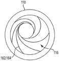
Fig. 1 is a perspective view of an illustrative inhaler article.
Fig. 2 is a schematic cross-sectional view of the exemplary inhaler article of fig. 1 along a longitudinal axis showing a helical projection along the capsule cavity.
Fig. 3 is a schematic cross-sectional view of the exemplary inhaler article of fig. 1 along a longitudinal axis showing a helical path along the capsule cavity.
Figure 4 is a perspective cross-sectional schematic view along a longitudinal axis of an exemplary capsule cavity having a helical projection along the capsule cavity.
Fig. 5 is a cross-sectional schematic view of an exemplary air inlet region along an axial axis.
Figure 6 is a schematic diagram in front perspective of an exemplary capsule cavity having six spiral features.
Detailed Description
The schematic drawings are not necessarily drawn to scale and are presented for illustrative, but not limiting, purposes. The figures depict one or more aspects described in the present disclosure. However, it should be understood that other aspects not depicted in the drawings fall within the scope and spirit of the present disclosure.
Fig. 1 shows an exemplary inhaler article 100. Fig. 2 is a schematic cross-sectional view of the exemplary inhaler article 100 of fig. 1 along a longitudinal axis LA, illustrating the spiral projection 162 along the capsule cavity 116. Fig. 3 is the exemplary inhaler article 100 of fig. 1 along a longitudinal axis L A A cross-sectional schematic view of the spiral channel 164 along the capsule cavity 116. Fig. 4 is a perspective cross-sectional cut-away schematic view along the longitudinal axis of an exemplary capsule cavity 116 having a spiral protrusion 162 along the capsule cavity 116. The inhaler article 100 comprises a mouthpieceLongitudinal axis L A A body 110 extending from a mouthpiece end 112 to a distal end 114, and a capsule cavity 116 defined within the body 110. Fig. 6 is a schematic front perspective view of an exemplary capsule cavity 116 having six spiral features 162/164. FIG. 5 is an exemplary air inlet region 150 along longitudinal axis L A Schematic cross-sectional view of (a).
The inhaler article 100 comprises a longitudinal axis L A A body 110 extending from a mouthpiece end 112 to a distal end 114, with an end piece element 120 located at the distal end 114. A capsule cavity 116 is defined within the body 110 and along the longitudinal axis L A Extending the length of the cavity. The capsule cavity 116 includes a spiral feature 162/164 on or in an inner surface of the capsule cavity 116. The helical feature 162/164 extends along the lumen length. An air inlet region 150 is between the end piece member 120 and the capsule cavity 116. The air inlet region 150 has an air inlet 113 and an air passageway 155 extending from the air inlet 113 to the capsule cavity 116. Porous support element 140 defines the downstream end of capsule cavity 116. The mouthpiece air channel 111 extends from the capsule cavity 116, through the porous support element 140 to the mouthpiece end 112.
The capsule cavity 116 includes one, two, three, four, five, six, or more spiral or helical features (channels 162 or protuberances 164) extending along the length of the capsule cavity 116. Two or more helical features (channels 162 or protrusions 164) may be symmetrically spaced from each other and fit into each other. Two or more helical features (channel 162 or protrusion 164) may share the same axis.
The inhaler article 100 comprises a longitudinal axis L A A body 110 extending from a mouthpiece end 112 to a distal end 114, and a capsule cavity 116 defined within the body 110. The mouthpiece air channel 111 extends from the capsule cavity 116 to the mouthpiece end 112. End piece member 120 is disposed within distal end 114 and extends into air inlet region 150 end piece member 120 may be configured to limit or prevent airflow through end piece member 120. The end piece element 120 may be formed from the body of cellulose acetate tow having a high Resistance To Draw (RTD) of at least 100mm of water per millimeter.
An air inlet region 150 is disposed within body 110 and extends to capsule cavity 116. The air inlet region 150 induces a swirling or vortex flow of the inhaled air into the capsule cavity. Air inlet region 150 may have an inner diameter defined by an inner surface 152 D1 And an outer diameter D2 defined by outer surface 151. The inner diameter D1 defined by the inner surface 152 forms an air passage 155 in the form of an open cylinder. Air inlet region 150 may include two air inlets or air channels 113 that extend from an outer surface 151 of air inlet region 150 to an air passage 155. The air inlet region 150 may comprise two air inlets 113 on opposite sides of the inhaler article 100 in communication with an air passage 155. The two opposing air inlets 113 extend substantially linearly between the outer surface 151 and the inner surface 152 of the air inlet region 150 to an air passage 155 extending along the inner diameter D of the open cylinder 155 1 In the tangential direction of the shaft. The openings of the two opposing air inlets 113 at the inner surface 152 are not aligned, in particular, in this embodiment, the two opposing air inlets 113 extend in substantially parallel directions along axes at the air inlet region 150 and the central longitudinal axis L of the inhaler article 100 A Extend on opposite sides thereof. Along the inner diameter D of the split cylinder 155 1 The tangential direction of the two opposing air inlets 113 causes a swirling or swirling air flow pattern into the capsule cavity 116 of the inhaler body 110.
The air inlet region 150 and porous support element 140 define the capsule cavity 116. A capsule 130 may be disposed within the cavity 116. The capsule 130 contains particles comprising nicotine. The air inlet region 150 and the porous support member 140 cooperate to longitudinally contain the capsule 130 within the capsule cavity 116. The mouthpiece end 112 is shown as having a concave end, with the main body 110 defining an open space at the mouthpiece end 112. Alternatively, the porous support element 140 may extend to the mouth end 112 to fill the entire mouth end 112. The capsule 130 has a longitudinal axis L within the capsule cavity A A coextensive axis of rotation.
The consumer may pierce end piece member 120 and puncture capsule 130 contained within capsule cavity 116 using a separate piercing member (not shown). The piercing element may be withdrawn from the inhaler article 100 and the end piece element 120 before the user or consumer draws on the inhaler article 100. The consumer may then draw on the inhaler article 100 to use the inhaler. Although the piercing element forms an opening in the end piece element 120, this is typically a small opening that does not significantly reduce the resistance to suction of the end piece element 120. In some embodiments, the end piece element 120 is resealable after the piercing element has been withdrawn from the end piece element 120.
Claims (20)
1. An inhaler article comprising:
a body extending along a longitudinal axis from a mouth end to a distal end;
an end piece element at the distal end;
a capsule cavity having an inner surface defining a cylindrical space within the body and extending a cavity length along the longitudinal axis, the capsule cavity comprising a spiral feature on or in the inner surface of the capsule cavity, the spiral feature being a protuberance or channel extending along the cavity length;
an air inlet region between the end piece element and the capsule cavity, the air inlet region having an air inlet and an air passageway extending from the air inlet to the capsule cavity, wherein the air inlet region induces a swirl in an intake air flow entering the capsule cavity;
a porous support element defining a downstream end of the capsule cavity;
a mouthpiece air passage extending from the capsule cavity through the porous support element to the mouthpiece end.
2. The inhaler article according to claim 1, wherein the helical feature is a groove or channel recessed into the inner surface of the capsule cavity.
3. The inhaler article according to claim 1, wherein the spiral feature is a protrusion extending away from the inner surface of the capsule cavity.
4. The inhaler article according to any one of claims 1 to 3 wherein the helical feature rotates at least 50% of one full rotation about the inner surface.
5. The inhaler article according to any one of claims 1 to 3 wherein the helical features have a pitch in the range 2mm to 8 mm.
6. The inhaler article of claim 1, wherein the helical feature comprises two helical features that each define a circular helix.
7. The inhaler article of claim 1, wherein the helical feature comprises three or more helical features that each define a circular helix.
8. An inhaler article according to claim 6 or 7, wherein the helical features are equally spaced from one another along the cavity length.
9. The inhaler article according to any one of claims 1 to 3 wherein the air inlet region comprises a swirl channel, the swirl channel being an open cylinder defining the air passageway, wherein the air passageway extends substantially coaxially along a longitudinal axis of the open cylinder and the swirl channel comprises two opposing air inlets into the air passageway in a tangential direction to an inner diameter of the open cylinder.
10. The inhaler article according to any one of claims 1 to 3 wherein the end piece element is configured to restrict or prevent airflow through the distal end to the capsule cavity.
11. An inhaler article according to any of claims 1 to 3, wherein the end piece element has a resistance to draw of greater than 100mm water and is formed from at least one of: cellulose and acetate; fibers and tows; and (6) sticking the adhesive paper.
12. An inhaler system comprising an inhaler article according to any preceding claim and a capsule disposed within a capsule cavity of the inhaler article, the capsule containing particles having a mass median aerodynamic diameter of 5 microns or less.
13. The inhaler system according to claim 12 wherein the particles have a mass median aerodynamic diameter in the range of 0.5 to 4 microns.
14. The inhaler system according to claim 12 wherein the particles have a mass median aerodynamic diameter in the range of 1 micron to 3 microns.
15. The inhaler system according to claim 12, wherein the capsule contains particles comprising nicotine.
16. The inhaler system according to any one of claims 12 to 15 wherein the capsule further contains a population consisting of perfume particles having a mass median aerodynamic diameter of 20 microns or greater.
17. The inhaler system according to claim 16, wherein the perfume particles have a mass median aerodynamic diameter of 50 microns or greater.
18. The inhaler system according to claim 16, wherein the perfume particles have a mass median aerodynamic diameter in the range from 50 to 200 microns.
19. The inhaler system according to claim 16, wherein the perfume particles have a mass median aerodynamic diameter in the range from 50 to 150 microns.
20. The inhaler system according to any one of claims 12 to 15, wherein the inhaler system further comprises a piercing element which is detachably engageable with the inhaler article to activate the capsule, and wherein the end piece element is configured to be pierced by the piercing element upon activation of the capsule.
Applications Claiming Priority (3)
| Application Number | Priority Date | Filing Date | Title |
|---|---|---|---|
| EP18164077 | 2018-03-26 | ||
| EP18164077.2 | 2018-03-26 | ||
| PCT/IB2019/052412 WO2019186372A1 (en) | 2018-03-26 | 2019-03-25 | Inhaler with vortex capsule cavity |
Publications (2)
| Publication Number | Publication Date |
|---|---|
| CN111867662A CN111867662A (en) | 2020-10-30 |
| CN111867662B true CN111867662B (en) | 2022-09-23 |
Family
ID=61800431
Family Applications (1)
| Application Number | Title | Priority Date | Filing Date |
|---|---|---|---|
| CN201980017201.3A Active CN111867662B (en) | 2018-03-26 | 2019-03-25 | Inhaler with vortex capsule cavity |
Country Status (6)
| Country | Link |
|---|---|
| EP (1) | EP3772258B1 (en) |
| JP (1) | JP7360392B2 (en) |
| KR (1) | KR20200131248A (en) |
| CN (1) | CN111867662B (en) |
| BR (1) | BR112020016652A2 (en) |
| WO (1) | WO2019186372A1 (en) |
Families Citing this family (4)
| Publication number | Priority date | Publication date | Assignee | Title |
|---|---|---|---|---|
| KR20220088421A (en) * | 2019-10-25 | 2022-06-27 | 필립모리스 프로덕츠 에스.에이. | An inhaler article having an open distal end and an inhaler system |
| WO2021171180A1 (en) * | 2020-02-26 | 2021-09-02 | Philip Morris Products S.A. | High barrier powder capsule |
| KR20230043142A (en) * | 2020-07-24 | 2023-03-30 | 필립모리스 프로덕츠 에스.에이. | inhaler items |
| WO2024026704A1 (en) * | 2022-08-03 | 2024-02-08 | 常州市派腾电子技术服务有限公司 | Atomizer and aerosol-generating device |
Citations (3)
| Publication number | Priority date | Publication date | Assignee | Title |
|---|---|---|---|---|
| WO1995005208A1 (en) * | 1993-08-18 | 1995-02-23 | Fisons Plc | Inhalator with breath flow regulation |
| WO2017109626A1 (en) * | 2015-12-24 | 2017-06-29 | Philip Morris Products S.A. | Nicotine powder delivery system |
| WO2018007886A1 (en) * | 2016-07-07 | 2018-01-11 | Philip Morris Products S.A. | Nicotine inhaler system |
Family Cites Families (10)
| Publication number | Priority date | Publication date | Assignee | Title |
|---|---|---|---|---|
| IT982765B (en) * | 1973-04-13 | 1974-10-21 | Farmaceutici Italia | INHALER DEVICE |
| JPS5045495A (en) * | 1973-08-24 | 1975-04-23 | ||
| AU693306B2 (en) * | 1995-01-23 | 1998-06-25 | Direct-Haler A/S | An inhaler |
| AU779693B2 (en) * | 1999-07-23 | 2005-02-03 | Mannkind Corporation | Unit dose capsules and dry powder inhaler |
| US20040206350A1 (en) * | 2002-12-19 | 2004-10-21 | Nektar Therapeutics | Aerosolization apparatus with non-circular aerosolization chamber |
| US9609893B2 (en) * | 2013-03-15 | 2017-04-04 | Rai Strategic Holdings, Inc. | Cartridge and control body of an aerosol delivery device including anti-rotation mechanism and related method |
| CN106170313B (en) * | 2014-04-28 | 2020-11-10 | 菲利普莫里斯生产公司 | Flavored nicotine powder inhaler |
| BR112018010830B1 (en) * | 2015-12-24 | 2023-04-11 | Philip Morris Products S.A. | NICOTINE PARTICLE CAPSULE |
| JP7086859B2 (en) * | 2016-05-31 | 2022-06-20 | フィリップ・モーリス・プロダクツ・ソシエテ・アノニム | Aerosol generation system with heated aerosol generation article |
| US10918135B2 (en) * | 2016-05-31 | 2021-02-16 | Altria Client Services Llc | Heat diffuser for an aerosol-generating system |
-
2019
- 2019-03-25 CN CN201980017201.3A patent/CN111867662B/en active Active
- 2019-03-25 EP EP19721073.5A patent/EP3772258B1/en active Active
- 2019-03-25 JP JP2020547062A patent/JP7360392B2/en active Active
- 2019-03-25 BR BR112020016652-9A patent/BR112020016652A2/en unknown
- 2019-03-25 WO PCT/IB2019/052412 patent/WO2019186372A1/en active Search and Examination
- 2019-03-25 KR KR1020207026561A patent/KR20200131248A/en not_active Application Discontinuation
Patent Citations (3)
| Publication number | Priority date | Publication date | Assignee | Title |
|---|---|---|---|---|
| WO1995005208A1 (en) * | 1993-08-18 | 1995-02-23 | Fisons Plc | Inhalator with breath flow regulation |
| WO2017109626A1 (en) * | 2015-12-24 | 2017-06-29 | Philip Morris Products S.A. | Nicotine powder delivery system |
| WO2018007886A1 (en) * | 2016-07-07 | 2018-01-11 | Philip Morris Products S.A. | Nicotine inhaler system |
Also Published As
| Publication number | Publication date |
|---|---|
| JP2021517026A (en) | 2021-07-15 |
| JP7360392B2 (en) | 2023-10-12 |
| RU2020131563A (en) | 2022-04-26 |
| BR112020016652A2 (en) | 2020-12-15 |
| US20210008307A1 (en) | 2021-01-14 |
| CN111867662A (en) | 2020-10-30 |
| WO2019186372A1 (en) | 2019-10-03 |
| EP3772258B1 (en) | 2023-10-25 |
| EP3772258C0 (en) | 2023-10-25 |
| EP3772258A1 (en) | 2021-02-10 |
| KR20200131248A (en) | 2020-11-23 |
Similar Documents
| Publication | Publication Date | Title |
|---|---|---|
| JP7249354B2 (en) | Inhaler with a porous support element with openings | |
| CN111465423B (en) | Inhaler with swirl channel | |
| KR102494208B1 (en) | Inhalers with Swirl End Plugs | |
| CN111867662B (en) | Inhaler with vortex capsule cavity | |
| CN111818955B (en) | Inhaler with composite porous support element | |
| CN109922851B (en) | Inhaler with sized cavity | |
| JP2019508015A (en) | Nicotine particle capsule | |
| CN111801026B (en) | Inhaler with porous support element having holes | |
| US11964099B2 (en) | Inhaler with vortex capsule cavity | |
| RU2783305C2 (en) | Inhaler with composite porous support element | |
| RU2783884C2 (en) | Inhaler with vortex cavity for capsule | |
| RU2784856C2 (en) | Inhaler with porous support element with holes | |
| RU2778721C2 (en) | Inhaler with vortex channel |
Legal Events
| Date | Code | Title | Description |
|---|---|---|---|
| PB01 | Publication | ||
| PB01 | Publication | ||
| SE01 | Entry into force of request for substantive examination | ||
| SE01 | Entry into force of request for substantive examination | ||
| GR01 | Patent grant | ||
| GR01 | Patent grant |