CN111864236A - Fuel cell humidification system and humidification method - Google Patents
Fuel cell humidification system and humidification method Download PDFInfo
- Publication number
- CN111864236A CN111864236A CN202010905282.5A CN202010905282A CN111864236A CN 111864236 A CN111864236 A CN 111864236A CN 202010905282 A CN202010905282 A CN 202010905282A CN 111864236 A CN111864236 A CN 111864236A
- Authority
- CN
- China
- Prior art keywords
- air
- housing
- water
- pipe
- outlet
- Prior art date
- Legal status (The legal status is an assumption and is not a legal conclusion. Google has not performed a legal analysis and makes no representation as to the accuracy of the status listed.)
- Pending
Links
Images


Classifications
-
- H—ELECTRICITY
- H01—ELECTRIC ELEMENTS
- H01M—PROCESSES OR MEANS, e.g. BATTERIES, FOR THE DIRECT CONVERSION OF CHEMICAL ENERGY INTO ELECTRICAL ENERGY
- H01M8/00—Fuel cells; Manufacture thereof
- H01M8/04—Auxiliary arrangements, e.g. for control of pressure or for circulation of fluids
- H01M8/04082—Arrangements for control of reactant parameters, e.g. pressure or concentration
- H01M8/04089—Arrangements for control of reactant parameters, e.g. pressure or concentration of gaseous reactants
- H01M8/04119—Arrangements for control of reactant parameters, e.g. pressure or concentration of gaseous reactants with simultaneous supply or evacuation of electrolyte; Humidifying or dehumidifying
- H01M8/04126—Humidifying
- H01M8/04134—Humidifying by coolants
-
- H—ELECTRICITY
- H01—ELECTRIC ELEMENTS
- H01M—PROCESSES OR MEANS, e.g. BATTERIES, FOR THE DIRECT CONVERSION OF CHEMICAL ENERGY INTO ELECTRICAL ENERGY
- H01M8/00—Fuel cells; Manufacture thereof
- H01M8/04—Auxiliary arrangements, e.g. for control of pressure or for circulation of fluids
- H01M8/04082—Arrangements for control of reactant parameters, e.g. pressure or concentration
- H01M8/04089—Arrangements for control of reactant parameters, e.g. pressure or concentration of gaseous reactants
- H01M8/04119—Arrangements for control of reactant parameters, e.g. pressure or concentration of gaseous reactants with simultaneous supply or evacuation of electrolyte; Humidifying or dehumidifying
- H01M8/04126—Humidifying
- H01M8/04149—Humidifying by diffusion, e.g. making use of membranes
-
- H—ELECTRICITY
- H01—ELECTRIC ELEMENTS
- H01M—PROCESSES OR MEANS, e.g. BATTERIES, FOR THE DIRECT CONVERSION OF CHEMICAL ENERGY INTO ELECTRICAL ENERGY
- H01M8/00—Fuel cells; Manufacture thereof
- H01M8/04—Auxiliary arrangements, e.g. for control of pressure or for circulation of fluids
- H01M8/04298—Processes for controlling fuel cells or fuel cell systems
- H01M8/04694—Processes for controlling fuel cells or fuel cell systems characterised by variables to be controlled
- H01M8/04828—Humidity; Water content
-
- Y—GENERAL TAGGING OF NEW TECHNOLOGICAL DEVELOPMENTS; GENERAL TAGGING OF CROSS-SECTIONAL TECHNOLOGIES SPANNING OVER SEVERAL SECTIONS OF THE IPC; TECHNICAL SUBJECTS COVERED BY FORMER USPC CROSS-REFERENCE ART COLLECTIONS [XRACs] AND DIGESTS
- Y02—TECHNOLOGIES OR APPLICATIONS FOR MITIGATION OR ADAPTATION AGAINST CLIMATE CHANGE
- Y02E—REDUCTION OF GREENHOUSE GAS [GHG] EMISSIONS, RELATED TO ENERGY GENERATION, TRANSMISSION OR DISTRIBUTION
- Y02E60/00—Enabling technologies; Technologies with a potential or indirect contribution to GHG emissions mitigation
- Y02E60/30—Hydrogen technology
- Y02E60/50—Fuel cells
-
- Y—GENERAL TAGGING OF NEW TECHNOLOGICAL DEVELOPMENTS; GENERAL TAGGING OF CROSS-SECTIONAL TECHNOLOGIES SPANNING OVER SEVERAL SECTIONS OF THE IPC; TECHNICAL SUBJECTS COVERED BY FORMER USPC CROSS-REFERENCE ART COLLECTIONS [XRACs] AND DIGESTS
- Y02—TECHNOLOGIES OR APPLICATIONS FOR MITIGATION OR ADAPTATION AGAINST CLIMATE CHANGE
- Y02P—CLIMATE CHANGE MITIGATION TECHNOLOGIES IN THE PRODUCTION OR PROCESSING OF GOODS
- Y02P70/00—Climate change mitigation technologies in the production process for final industrial or consumer products
- Y02P70/50—Manufacturing or production processes characterised by the final manufactured product
Landscapes
- Life Sciences & Earth Sciences (AREA)
- Engineering & Computer Science (AREA)
- Manufacturing & Machinery (AREA)
- Sustainable Development (AREA)
- Sustainable Energy (AREA)
- Chemical & Material Sciences (AREA)
- Chemical Kinetics & Catalysis (AREA)
- Electrochemistry (AREA)
- General Chemical & Material Sciences (AREA)
- Fuel Cell (AREA)
Abstract
The invention discloses a fuel cell humidifying system and a humidifying method, the humidifying system comprises an air filtering mechanism, an air flow meter, an air compression mechanism, a galvanic pile, a heat exchanger and an atomizing mechanism, wherein an air outlet of the air filtering mechanism is communicated with an air inlet of the air flow meter through a pipeline, an air outlet of the air flow meter is communicated with an air inlet of the air compression mechanism through a pipeline, an air outlet of the air compression mechanism is communicated with an air inlet of the galvanic pile through a pipeline, an air outlet of the galvanic pile is communicated with a water vapor inlet of the heat exchanger through a pipeline, a water outlet of the heat exchanger is communicated with a water path inlet of the atomizing mechanism through a pipeline, a water mist outlet of the atomizing mechanism is communicated with the air inlet of the galvanic pile through a pipeline, and an ejector. Aiming at the problems of complex structure, large volume, and overhigh stability or cost of the existing air channel humidifying device, the invention provides a fuel cell humidifying system and a humidifying method.
Description
Technical Field
The present invention relates to the field of fuel cells. More particularly, the present invention relates to a fuel cell humidification system and a humidification method.
Background
The fuel cell is a chemical device for directly converting chemical energy of fuel into electric energy, and is composed of multiple bipolar plates and MEA (membrane electrode assembly) electrodes.
In the operation process of the fuel cell stack, the membrane humidity of the MEA needs to be moderate, if the membrane humidity is too low, the electrical conductivities of the membrane and the three-dimensional reagent are too low, the internal resistance of the cell is increased, the performance is reduced, if the membrane humidity is too high, flooding is caused, the resistance of gas entering an electrode is increased, and the performance is not good.
During the operation of the fuel cell stack, the air path needs to be properly humidified to ensure that the MEA is in an optimal state. The humidification method mainly includes a shower method, a bubbling method, and a membrane humidifier. The spraying and bubbling modes have high requirements on equipment and sites, except for humidification, dehumidification equipment is required, the humidification effect has large fluctuation, the timeliness is poor, and the stability is poor; the membrane humidifier adopts a dry-wet gas convection mode for humidification, the humidification effect is not controllable, and the membrane humidifier on the market is high in cost and difficult to meet the humidification requirement of the difference of the performance of the galvanic pile;
patent CN201721766270.9 discloses a gas humidifying device for fuel cell testing equipment, which utilizes water atomization and then sprays on a heating plate for heating, and injects the water after gasification into an air pipeline for mixing, the device has a complex structure and a large volume, and can only be used in testing platform equipment; patent 200710030353.6 discloses a full-automatic humidification and water management system for hydrogen fuel cell, which includes ultrasonic atomization box, condenser, electric pile air circuit, cooler and control assembly, the components are many, the volume is big, and the cost is also high.
Disclosure of Invention
The invention aims to provide a fuel cell humidifying system and a humidifying method aiming at the problems of complex structure, large volume and high stability or cost of the existing air channel humidifying device.
To achieve these objects and other advantages in accordance with the purpose of the invention, there is provided a fuel cell humidification system including an air filtering mechanism, an air flow meter, an air compressing mechanism, a stack, a heat exchanger, and an atomizing mechanism, the air outlet of the air filtering mechanism is communicated with the air inlet of the air flow meter through a pipeline, the air outlet of the air flow meter is communicated with the air inlet of the air compression mechanism through a pipeline, an air outlet of the air compression mechanism is communicated with an air inlet of the galvanic pile through a pipeline, an air outlet of the galvanic pile is communicated with a water-air inlet of the heat exchanger through a pipeline, the water outlet of the heat exchanger is communicated with the water path inlet of the atomization mechanism through a pipeline, the water mist outlet of the atomization mechanism is communicated with the air inlet of the galvanic pile through a pipeline, and an ejector is arranged on the pipeline connecting the water outlet of the atomization mechanism and the air inlet of the galvanic pile.
Preferably, in the fuel cell humidification system, the heat exchanger comprises a first housing, an air inlet pipe, an air outlet pipe, a cooling pipeline and a drain pipe, the air inlet pipe and the air outlet pipe are respectively arranged at two sides of the first housing, one end of the air inlet pipe and one end of the air outlet pipe are both communicated with the inside of the first housing, the other end of the air inlet pipe is respectively communicated with an air outlet of the electric pile through a pipeline, the cooling pipeline is arranged in the first housing, a liquid inlet and a liquid outlet of the cooling pipeline respectively penetrate through the inner wall of the first housing and extend out of the first housing, a liquid outlet is arranged at the lower end of the first housing, the drain pipe is vertically arranged at the lower end of the first housing, an opening at the upper end of the drain pipe is communicated with the liquid outlet of the first housing, and the lower end of the drain pipe is communicated with a water path inlet, the drain pipe is also provided with a one-way valve.
Preferably, a fuel cell humidification system in, cooling conduit includes the first pipe that many intervals set up, is located two of both sides first pipe homogeneous end opening other end seals, and the open end of the two is worn out first casing constitutes cooling conduit's inlet and liquid outlet, other the both ends of first pipe seal and all with the interior wall connection of first casing, through second pipe intercommunication between two arbitrary adjacent first pipes, equal rotatable cover is equipped with a drum on the first pipe, it has a plurality of cooling fins all along its radial setting to follow the circumference equipartition on the drum.
Preferably, in the humidification system for a fuel cell, two ends of the cylinder are respectively rotatably connected to the corresponding circular tubes through bearings.
Preferably, the fuel cell humidification system further comprises a first controller, a first pressure sensor is arranged at the liquid outlet of the first shell, and the first pressure sensor and the one-way valve are electrically connected with the first controller respectively.
Preferably, a fuel cell humidification system in, atomizing mechanism includes second casing, oral siphon and at least one ultrasonic atomization piece, the vertical setting of oral siphon is in second casing upper end, the upper end of oral siphon with the outlet of heat exchanger crosses the pipeline intercommunication, its lower extreme with the inside intercommunication of second casing, be equipped with on the lateral wall of second casing the water smoke export, the water inlet of ejector pass through the pipeline with water smoke export intercommunication, ultrasonic atomization piece level sets up in the second casing, ultrasonic atomization piece lower extreme all is equipped with the cotton stick of humidification, the upper end of the cotton stick of humidification upwards extends to corresponding ultrasonic atomization piece lower extreme, its lower extreme downwardly extends to in the liquid in the second casing.
Preferably, the fuel cell humidification system further comprises a water outlet pipe, the water outlet pipe is vertically arranged at the lower end of the second shell, and an opening at the upper end of the water outlet pipe is communicated with the inside of the second shell.
Preferably, the fuel cell humidification system further comprises a second controller, a second pressure sensor and an electromagnetic valve, the second pressure sensor is disposed on the bottom wall of the second housing, the electromagnetic valve is disposed on the water outlet pipe, and the second pressure sensor and the electromagnetic valve are respectively electrically connected to the second controller.
Preferably, in the humidification system for a fuel cell, the ultrasonic atomization sheet is provided in plurality, and the plurality of ultrasonic atomization sheets are arranged in the second housing at intervals.
The invention also provides a fuel cell humidifying method, which adopts the fuel cell humidifying system and comprises the following steps:
s1, introducing the air filtered by the air filtering mechanism into the air compression mechanism;
s2, sending the water mist discharged by the atomizing mechanism and the air discharged by the air compression mechanism in the S1 to the electric pile for humidification through the ejector;
and S3, discharging the air discharged by the electric pile into the heat exchanger, discharging the water discharged by the heat exchanger into the atomizing mechanism, and supplementing water to the atomizing mechanism.
The invention provides a fuel cell humidification system utilizing the principle of re-atomization and injection after condensation of gas at an air outlet of a galvanic pile aiming at the problems of complex structure, large volume, and high stability or cost of the existing air path humidification device, and a humidification scheme for re-injecting water vapor at the air outlet of the galvanic pile into an air inlet of the galvanic pile for humidification after condensation of the water vapor at the air outlet of the galvanic pile through an atomization cavity;
additional advantages, objects, and features of the invention will be set forth in part in the description which follows and in part will become apparent to those having ordinary skill in the art upon examination of the following or may be learned from practice of the invention.
Drawings
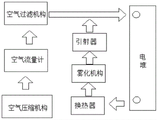
Fig. 1 is a schematic structural diagram of a humidification system of a fuel cell according to the present invention;
FIG. 2 is a schematic structural diagram of a heat exchanger according to the present invention;
FIG. 3 is a cross-sectional view of a heat exchanger according to the present invention;
fig. 4 is a schematic structural diagram of an atomizing mechanism according to the present invention.
Detailed Description
The present invention is further described in detail below with reference to the attached drawings so that those skilled in the art can implement the invention by referring to the description text.
It should be noted that in the description of the present invention, the terms "lateral", "longitudinal", "upper", "lower", "front", "rear", "left", "right", "vertical", "horizontal", "top", "bottom", "inner", "outer", etc. indicate orientations or positional relationships based on those shown in the drawings, and are only for convenience of description and simplicity of description, and do not indicate or imply that the referred device or element must have a specific orientation, be constructed and operated in a specific orientation, and thus, should not be construed as limiting the present invention.
As shown in fig. 1, an embodiment of the present invention provides a fuel cell humidification system, which includes an air filtering mechanism, an air flow meter, an air compressing mechanism, a stack, a heat exchanger, and an atomizing mechanism, wherein an air outlet of the air filtering mechanism is communicated with an air inlet of the air flow meter through a pipeline, an air outlet of the air flow meter is communicated with an air inlet of the air compressing mechanism through a pipeline, an air outlet of the air compressing mechanism is communicated with an air inlet of the stack through a pipeline, an air outlet of the stack is communicated with a water-vapor inlet of the heat exchanger through a pipeline, a water outlet of the heat exchanger is communicated with a water-path inlet of the atomizing mechanism through a pipeline, a water-mist outlet of the atomizing mechanism is communicated with an air inlet of the stack through a pipeline, and an ejector is disposed on the pipeline connecting the air filtering mechanism and the air.
In the above embodiment, the air filtering mechanism adopts a chemical air filter, and can filter dust and impurity particles in the air, and can also filter harmful gases such as residual carbon monoxide, sulfur dioxide, nitrogen oxides and the like in the air which damage the galvanic pile, and the air filtered by the air filtering mechanism is introduced into the air compression mechanism through the air flow meter and sent into the galvanic pile of the fuel cell, wherein the outlet pressure of the inlet of the air flow meter needs to be consistent with the atmospheric pressure, so that the accuracy of the mass flow measured by the air flow meter can be ensured; then, the water mist discharged by the atomizing mechanism and the high-pressure air discharged by the air filtering mechanism are sent to the galvanic pile together through the ejector to humidify the galvanic pile; the water flow generated in the heat exchanger is discharged to the atomizing mechanism to be used as a source of water mist in the atomizing mechanism, so that the atomized water is recycled.
Preferably, as another embodiment of the present invention, as shown in fig. 2 to 3, the heat exchanger includes a first housing 1, an air inlet pipe 2, an air outlet pipe 3, a cooling pipeline and a water outlet pipe 4, the air inlet pipe 2 and the air outlet pipe 3 are respectively disposed at two sides of the first housing 1, and one end of the air inlet pipe 2 and one end of the air outlet pipe 3 are both communicated with the inside of the first housing 1, the other end of the air inlet pipe 2 is respectively communicated with an air outlet of the cell stack through a pipeline, the cooling pipeline is disposed in the first housing 1, a liquid inlet and a liquid outlet thereof respectively penetrate through an inner wall of the first housing 1 and extend to the outside of the first housing 1, a liquid outlet is disposed at a lower end of the first housing 1, the water outlet pipe 4 is vertically disposed at the lower end of the first housing 1, and an opening at an upper end thereof is communicated with the liquid outlet of the first housing, the lower end of the water pipe is communicated with a waterway inlet of the atomizing mechanism through a pipeline, and a one-way valve is further arranged on the drain pipe 4.
In the above embodiment, the inlet and the liquid outlet of cooling pipe are connected into external coolant circulation system, circulate in introducing cooling pipe with the coolant liquid to air to getting into first casing 1 through intake pipe 2 cools off, thereby after the air cooling, thereby moisture wherein can liquefy and fall in first casing 1, and arrange atomizing mechanism through drain pipe 4.
Preferably, as another embodiment of the present invention, the cooling pipe includes a plurality of first circular pipes 5 arranged at intervals, one end of each of the two first circular pipes 5 located at two sides is open, and the other end is closed, open ends of the two first circular pipes penetrate through the first housing 1 to form a liquid inlet and a liquid outlet of the cooling pipe, two ends of each of the other first circular pipes 5 are closed and are connected to an inner wall of the first housing 1, any two adjacent first circular pipes 5 are communicated with each other through a second circular pipe 6, each of the first circular pipes 5 is rotatably sleeved with a cylinder 7, and a plurality of cooling fins 8 arranged along a radial direction of the cylinder 7 are uniformly distributed on the cylinder 7 along a circumferential direction.
In the above embodiment, cooling tube is constituteed to many first pipes 5 and many second pipes 6, in order to strengthen cooling tube's cooling effect, drum 7 is established to the cover on every first pipe 5, drum 7 is last to have a plurality ofly all along its radial cooling fin 8 that sets up along the circumference equipartition, enlarge the area of contact of air in first pipe 5 and the first casing 1, moisture in the air in the first casing 1 behind the condensation one-tenth drop of water on cooling fin 8, drive drum 7 through the air current that gets into in the first casing 1 simultaneously and rotate on the first pipe 5 that corresponds, thereby the easier drops of water that spills on drum 7 and the cooling fin 8 to first casing 1.
Preferably, as another embodiment of the present invention, two ends of the cylinder 7 are rotatably connected to the corresponding circular tubes through bearings 9.
In the above embodiment, the two ends of the cylinder 7 are respectively rotatably connected with the corresponding first circular tubes 5 through the bearings 9, the inner ring of each bearing 9 is coaxially connected with the corresponding first circular tube 5, and the outer ring of each bearing is connected with the end of the cylinder 7, so that the cylinder 7 and the corresponding first circular tube 5 can rotate more easily.
Preferably, as another embodiment of the present invention, the liquid level controller further includes a first controller, a first pressure sensor is disposed at the liquid outlet of the first housing 1, and the first pressure sensor and the one-way valve are electrically connected to the first controller respectively.
In the above embodiment, the first pressure sensor is arranged at the liquid outlet of the first casing 1 to obtain the water pressure at the liquid outlet of the first casing 1, the check valve adopts the electromagnetic valve, and when the water pressure is too high, that is, when the accumulated water in the first casing 1 is too much, the first controller controls the check valve to open, so as to discharge the excess water in the first casing 1 in time.
Preferably, as another embodiment of the present invention, as shown in fig. 4, the atomizing mechanism includes a second housing 10, a water inlet pipe 11 and at least one ultrasonic atomizing plate 12, the water inlet pipe 11 is vertically disposed at the upper end of the second housing 10, the upper end of the water inlet pipe 11 is in pipeline communication with the water outlet of the heat exchanger, the lower end of the water inlet pipe is in pipeline communication with the inside of the second housing 10, the side wall of the second housing 10 is provided with the water mist outlet, the water inlet of the ejector is in pipeline communication with the water mist outlet, the ultrasonic atomizing plate 12 is horizontally disposed in the second housing 10, the lower ends of the ultrasonic atomizing plates 12 are respectively provided with a humidifying cotton rod 13, the upper end of each humidifying cotton rod 13 extends upward to the lower end of the corresponding ultrasonic atomizing plate 12, and the lower end of each humidifying cotton rod extends downward to the liquid in the second housing 10.
In the above embodiment, with the atomizing mechanism access fuel cell humidification system in, discharged water passes through oral siphon 11 and gets into in the second casing 10 in the heat exchanger, and form ponding in second casing 10, be provided with a plurality of ultrasonic atomization pieces 12 through the interval in second casing 10, and set up humidification cotton stick 13 at every ultrasonic atomization piece 12 lower extreme, 13 lower extremes of humidification cotton stick immerse in the ponding in the second casing 10, in order to provide liquid water to the ultrasonic atomization piece 12 that corresponds through humidification cotton stick 13, ultrasonic atomization piece 12 utilizes the electron high frequency to vibrate, through the high frequency resonance of ceramic atomization piece, break up liquid water molecule structure and produce the water smoke that naturally drifts away, pass through the water inlet with fuel cell humidification system's ejector through pipeline and water smoke outlet intercommunication again, send the water smoke that produces in the second casing 10 to the pile through the ejector.
Preferably, as another embodiment of the present invention, the present invention further comprises a water outlet pipe 14, wherein the water outlet pipe 14 is vertically arranged at the lower end of the second casing 10, and the upper end opening of the water outlet pipe is communicated with the inside of the second casing 10; the water outlet pipe is characterized by further comprising a second controller, a second pressure sensor and an electromagnetic valve, wherein the second pressure sensor is arranged on the bottom wall of the second shell 10, the electromagnetic valve is arranged on the water outlet pipe 14, and the second pressure sensor and the electromagnetic valve are respectively electrically connected with the second controller.
In the above embodiment, by providing the second pressure sensor on the water outlet pipe 14, the water pressure at the bottom wall of the second housing 10 is obtained by the second pressure sensor, the pressure threshold is set in the second controller in advance, and when the water pressure obtained by the second pressure sensor exceeds the pressure threshold, the controller controls the electromagnetic valve to open the water discharge, so as to reduce the water level of the accumulated water in the second housing 10 and prevent the ultrasonic atomization sheet 12 from immersing in the accumulated water in the second housing 10.
The invention also provides a humidifying method of the fuel cell humidifying system, which comprises the following steps:
s1, introducing the air filtered by the air filtering mechanism into the air compression mechanism;
s2, sending the water mist discharged by the atomizing mechanism and the air discharged by the air compression mechanism in the S1 to the electric pile for humidification through the ejector;
and S3, discharging the air discharged by the electric pile into the heat exchanger, discharging the water discharged by the heat exchanger into the atomizing mechanism, and supplementing water to the atomizing mechanism.
While embodiments of the invention have been described above, it is not limited to the applications set forth in the description and the embodiments, which are fully applicable to various fields of endeavor for which the invention may be embodied with additional modifications as would be readily apparent to those skilled in the art, and the invention is therefore not limited to the details given herein and to the embodiments shown and described without departing from the generic concept as defined by the claims and their equivalents.
Claims (10)
1. The utility model provides a fuel cell humidification system, its characterized in that, includes air filter mechanism, air flow meter, air compression mechanism, galvanic pile, heat exchanger and atomizing mechanism, air filter mechanism's gas outlet with air flow meter's air inlet passes through the pipeline intercommunication, air flow meter's gas outlet with air compression mechanism's air inlet passes through the pipeline intercommunication, air compression mechanism's gas outlet with the air inlet of galvanic pile passes through the pipeline intercommunication, the air outlet of galvanic pile with the aqueous vapor entry of heat exchanger passes through the pipeline intercommunication, the outlet of heat exchanger with atomizing mechanism's water route entry passes through the pipeline intercommunication, atomizing mechanism's water smoke export with the air inlet of galvanic pile passes through the pipeline intercommunication, and is equipped with the ejector on the pipeline of connecting the two.
2. The fuel cell humidification system of claim 1, wherein the heat exchanger comprises a first housing (1), an air inlet pipe (2), an air outlet pipe (3), a cooling pipeline and a water outlet pipe (4), the air inlet pipe (2) and the air outlet pipe (3) are respectively arranged at two sides of the first housing (1), one end of the air inlet pipe (2) and one end of the air outlet pipe (3) are both communicated with the inside of the first housing (1), the other end of the air inlet pipe (2) is respectively communicated with the air outlet of the electric pile through a pipeline, the cooling pipeline is arranged in the first housing (1), a liquid inlet and a liquid outlet of the cooling pipeline respectively penetrate through the inner wall of the first housing (1) and extend to the outside of the first housing (1), a liquid outlet is arranged at the lower end of the first housing (1), the water outlet pipe (4) is vertically arranged at the lower end of the first housing (1), and the upper end opening of the water outlet pipe is communicated with the liquid outlet of the first shell (1), the lower end of the water outlet pipe is communicated with the water path inlet of the atomizing mechanism through a pipeline, and the water outlet pipe (4) is also provided with a one-way valve.
3. The fuel cell humidification system of claim 2, wherein the cooling pipe comprises a plurality of first circular pipes (5) arranged at intervals, two of the first circular pipes (5) located at two sides are closed at one end and the other end of the first circular pipe is closed at the other end, the open ends of the first circular pipes penetrate through the first shell (1) and form the liquid inlet and the liquid outlet of the cooling pipe, the two ends of the first circular pipes (5) are closed and connected with the inner wall of the first shell (1), any two adjacent first circular pipes (5) are communicated with each other through the second circular pipe (6), a cylinder (7) is sleeved on each first circular pipe (5) in a rotatable manner, and a plurality of cooling fins (8) are uniformly arranged on each cylinder (7) along the radial direction of the cylinder along the circumferential direction.
4. A fuel cell humidification system as claimed in claim 3 wherein the ends of the cylinder (7) are each rotatably connected to the respective circular tube by bearings (9).
5. The fuel cell humidification system of claim 2, further comprising a first controller, wherein a first pressure sensor is disposed at the liquid outlet of the first housing (1), and the first pressure sensor and the check valve are electrically connected to the first controller, respectively.
6. The fuel cell humidification system of any one of claims 1 to 5, wherein the atomization mechanism comprises a second housing (10), a water inlet pipe (11) and at least one ultrasonic atomization sheet (12), the water inlet pipe (11) is vertically arranged at the upper end of the second housing (10), the upper end of the water inlet pipe (11) is in pipe communication with a water outlet of the heat exchanger, the lower end of the water inlet pipe is in pipe communication with the inside of the second housing (10), the side wall of the second housing (10) is provided with the water mist outlet, the water inlet of the ejector is in pipe communication with the water mist outlet, the ultrasonic atomization sheet (12) is horizontally arranged in the second housing (10), the lower ends of the ultrasonic atomization sheets (12) are provided with humidification cotton sticks (13), the upper ends of the humidification cotton sticks (13) extend upwards to the corresponding lower ends of the ultrasonic atomization sheets (12), the lower end of which extends downwardly into the liquid in the second housing (10).
7. A fuel cell humidification system as claimed in claim 6 further comprising a water outlet pipe (14), said water outlet pipe (14) being disposed vertically at the lower end of said second housing (10) and having its upper end opening communicating with the interior of said second housing (10).
8. A fuel cell humidification system as claimed in claim 7 further comprising a second controller, a second pressure sensor disposed on a bottom wall of said second housing (10), and a solenoid valve disposed on said water outlet pipe (14), said second pressure sensor and solenoid valve being electrically connected to said second controller, respectively.
9. A fuel cell humidification system as claimed in claim 6 wherein said ultrasonic atomization plate (12) is provided in plurality, and a plurality of said ultrasonic atomization plates (12) are provided at intervals in said second housing (10).
10. A humidification method for a fuel cell humidification system using the fuel cell humidification system of any one of claims 1 to 9, comprising the steps of:
s1, introducing the air filtered by the air filtering mechanism into the air compression mechanism;
s2, sending the water mist discharged by the atomizing mechanism and the air discharged by the air compression mechanism in the S1 to the electric pile for humidification through the ejector;
and S3, discharging the air discharged by the electric pile into the heat exchanger, discharging the water discharged by the heat exchanger into the atomizing mechanism, and supplementing water to the atomizing mechanism.
Priority Applications (1)
| Application Number | Priority Date | Filing Date | Title |
|---|---|---|---|
| CN202010905282.5A CN111864236A (en) | 2020-09-01 | 2020-09-01 | Fuel cell humidification system and humidification method |
Applications Claiming Priority (1)
| Application Number | Priority Date | Filing Date | Title |
|---|---|---|---|
| CN202010905282.5A CN111864236A (en) | 2020-09-01 | 2020-09-01 | Fuel cell humidification system and humidification method |
Publications (1)
| Publication Number | Publication Date |
|---|---|
| CN111864236A true CN111864236A (en) | 2020-10-30 |
Family
ID=72966932
Family Applications (1)
| Application Number | Title | Priority Date | Filing Date |
|---|---|---|---|
| CN202010905282.5A Pending CN111864236A (en) | 2020-09-01 | 2020-09-01 | Fuel cell humidification system and humidification method |
Country Status (1)
| Country | Link |
|---|---|
| CN (1) | CN111864236A (en) |
Cited By (2)
| Publication number | Priority date | Publication date | Assignee | Title |
|---|---|---|---|---|
| CN113178597A (en) * | 2021-04-20 | 2021-07-27 | 内蒙古民族大学 | Fuel cell using hydrogen energy source as drive and fixing structure thereof |
| CN113299956A (en) * | 2021-04-28 | 2021-08-24 | 一汽解放汽车有限公司 | Fuel cell engine test system |
-
2020
- 2020-09-01 CN CN202010905282.5A patent/CN111864236A/en active Pending
Cited By (2)
| Publication number | Priority date | Publication date | Assignee | Title |
|---|---|---|---|---|
| CN113178597A (en) * | 2021-04-20 | 2021-07-27 | 内蒙古民族大学 | Fuel cell using hydrogen energy source as drive and fixing structure thereof |
| CN113299956A (en) * | 2021-04-28 | 2021-08-24 | 一汽解放汽车有限公司 | Fuel cell engine test system |
Similar Documents
| Publication | Publication Date | Title |
|---|---|---|
| CN101577342B (en) | Fuel cell with humidification zone of single cell | |
| KR20180067255A (en) | Fuel cell system | |
| CN106935886A (en) | A kind of gases humidification apparatus | |
| CN103069222B (en) | Fuel cell humidifier | |
| CN111864236A (en) | Fuel cell humidification system and humidification method | |
| US8541139B2 (en) | Humidifier including an auxiliary humidifier utilzing electroosmosis | |
| CN207896211U (en) | A kind of air gas supply humidification ICS intercooler system for Proton Exchange Membrane Fuel Cells | |
| JP2005032707A (en) | Cooling device of air cooled fuel cell | |
| KR102609395B1 (en) | Humidification and cooling device for fuel cell | |
| CN111987334A (en) | Controllable air humidifying device of hydrogen fuel cell | |
| CN102324537B (en) | Humidification system of fuel cell | |
| CN102607126A (en) | External pressure hollow fiber membrane humidifier | |
| CN210926173U (en) | External temperature-increasing humidifier for fuel cell gas | |
| CN108091910A (en) | A kind of porous media humidifier for fuel cell | |
| CN213520056U (en) | Fuel cell humidification system | |
| CN213124505U (en) | Fuel cell humidification system | |
| CN112290052A (en) | Cooling and humidifying integrated system of fuel cell | |
| CN213520057U (en) | Gas humidifying device of fuel cell system | |
| CN112490474B (en) | Gas humidifying device of fuel cell system | |
| CN215911444U (en) | High-pressure atomization humidifier for fuel cell testing equipment | |
| CN203071171U (en) | Air-inlet humidifying adjustable device of fuel cell engine | |
| CN206992227U (en) | A kind of gases humidification apparatus | |
| CN112838245A (en) | Fuel cell humidifier device, fuel cell system and humidification processing method thereof | |
| CN218221802U (en) | Simple water-gas separation cooling device and fuel cell system applying same | |
| CN213124504U (en) | Atomizing mechanism for fuel cell humidifying system |
Legal Events
| Date | Code | Title | Description |
|---|---|---|---|
| PB01 | Publication | ||
| PB01 | Publication | ||
| SE01 | Entry into force of request for substantive examination | ||
| SE01 | Entry into force of request for substantive examination |