CN111854569A - A double-station suction cup runout detection mechanism for automobile compressors - Google Patents
A double-station suction cup runout detection mechanism for automobile compressors Download PDFInfo
- Publication number
- CN111854569A CN111854569A CN202010817791.2A CN202010817791A CN111854569A CN 111854569 A CN111854569 A CN 111854569A CN 202010817791 A CN202010817791 A CN 202010817791A CN 111854569 A CN111854569 A CN 111854569A
- Authority
- CN
- China
- Prior art keywords
- plate
- assembly
- cylinder
- seat
- fixed
- Prior art date
- Legal status (The legal status is an assumption and is not a legal conclusion. Google has not performed a legal analysis and makes no representation as to the accuracy of the status listed.)
- Pending
Links
- 230000007246 mechanism Effects 0.000 title claims abstract description 38
- 238000001514 detection method Methods 0.000 title claims abstract description 33
- 238000003825 pressing Methods 0.000 claims abstract description 32
- 238000006073 displacement reaction Methods 0.000 claims abstract description 25
- RYGMFSIKBFXOCR-UHFFFAOYSA-N Copper Chemical compound [Cu] RYGMFSIKBFXOCR-UHFFFAOYSA-N 0.000 claims description 16
- 229910052802 copper Inorganic materials 0.000 claims description 16
- 239000010949 copper Substances 0.000 claims description 16
- 238000007667 floating Methods 0.000 claims description 16
- 238000009434 installation Methods 0.000 claims description 11
- 239000007769 metal material Substances 0.000 claims description 2
- 229910052755 nonmetal Inorganic materials 0.000 claims description 2
- 238000004519 manufacturing process Methods 0.000 abstract description 6
- 238000005259 measurement Methods 0.000 abstract description 4
- 238000000926 separation method Methods 0.000 abstract description 4
- 238000013461 design Methods 0.000 abstract description 2
- 238000012360 testing method Methods 0.000 description 16
- 238000000034 method Methods 0.000 description 13
- 239000000306 component Substances 0.000 description 11
- 230000008569 process Effects 0.000 description 11
- 238000010586 diagram Methods 0.000 description 7
- 238000007689 inspection Methods 0.000 description 6
- 239000000463 material Substances 0.000 description 2
- 230000003252 repetitive effect Effects 0.000 description 2
- 238000004378 air conditioning Methods 0.000 description 1
- 230000003139 buffering effect Effects 0.000 description 1
- 239000008358 core component Substances 0.000 description 1
- 238000011161 development Methods 0.000 description 1
- 238000005516 engineering process Methods 0.000 description 1
- 230000003993 interaction Effects 0.000 description 1
- 230000009191 jumping Effects 0.000 description 1
- 238000012423 maintenance Methods 0.000 description 1
- 230000003287 optical effect Effects 0.000 description 1
- 238000003908 quality control method Methods 0.000 description 1
- 230000009466 transformation Effects 0.000 description 1
Images


Classifications
-
- G—PHYSICS
- G01—MEASURING; TESTING
- G01B—MEASURING LENGTH, THICKNESS OR SIMILAR LINEAR DIMENSIONS; MEASURING ANGLES; MEASURING AREAS; MEASURING IRREGULARITIES OF SURFACES OR CONTOURS
- G01B5/00—Measuring arrangements characterised by the use of mechanical techniques
- G01B5/0025—Measuring of vehicle parts
Landscapes
- Physics & Mathematics (AREA)
- General Physics & Mathematics (AREA)
- Automatic Assembly (AREA)
Abstract
Description
技术领域technical field
本发明涉及的是一种汽车压缩机用的双工位吸盘跳动量检测机构,属于自动化检测设备技术领域。The invention relates to a double-station suction cup runout detection mechanism for automobile compressors, which belongs to the technical field of automatic detection equipment.
背景技术Background technique
随着汽车行业的迅速发展,汽车空调压缩机离合器的需求量也逐年增加,其中吸盘作为离合器的核心零部件之一,其质量决定着整个离合器的产品性能,而吸盘跳动量参数又是吸盘最为关键的指标之一,因此吸盘跳动量的测量对吸盘成品的质量管控尤为重要。目前的产品检测工序对于吸盘产品跳动量的检测控制手段非常缺乏,且检测手段单一,只能采用标准的偏摆仪进行检测,检测过程非常复杂,效率低,且由于人为因素的影响,检测精度也得不到保证,没有方便可靠的专用检测设备可以满足市场需求。因此研制一种操作简单,精度高,效率高,检测稳定的专业检测机构已是迫在眉睫。With the rapid development of the automobile industry, the demand for automobile air-conditioning compressor clutches is also increasing year by year. The suction cup is one of the core components of the clutch, and its quality determines the product performance of the entire clutch, and the suction cup runout parameter is the most important It is one of the key indicators, so the measurement of the suction cup runout is particularly important for the quality control of the suction cup finished product. The current product inspection process is very lacking in the detection and control means of the runout of the sucker product, and the detection method is single, and can only be detected by a standard deflection instrument. The detection process is very complicated and the efficiency is low. Due to the influence of human factors, the detection accuracy There is no guarantee, there is no convenient and reliable special testing equipment to meet the market demand. Therefore, it is urgent to develop a professional testing mechanism with simple operation, high precision, high efficiency and stable detection.
现有的吸盘跳动量检测工序主要通过操作人员手工将吸盘产品通过螺母固定在检测轴上,再将检测轴安装至偏摆仪上,然后操作人员手动调整百分表表架,将百分表表针调整至待检产品的检测位置,然后慢慢地单方向旋转吸盘,通过百分表指针摆动得出检测结果,整个检测过程操作非常复杂,人为影响因素大,检测精度差,检测效率低,操作人员重复劳动强度大。In the existing suction cup runout detection process, the operator manually fixes the suction cup product on the detection shaft through a nut, and then installs the detection shaft on the yaw meter, and then the operator manually adjusts the dial indicator frame to place the dial indicator. Adjust the needle to the detection position of the product to be inspected, then slowly rotate the suction cup in one direction, and obtain the inspection result by swinging the dial indicator pointer. The entire inspection process is very complicated, with large human factors, poor inspection accuracy, and low inspection efficiency. The operator has high repetitive labor intensity.
发明内容SUMMARY OF THE INVENTION
本发明的目的在于解决上述现有的吸盘跳动量检测方法和设备存在的检测精度差,操作繁琐,效率低下等问题,提出一种汽车压缩机用的双工位吸盘跳动量检测机构,具有操作简单安全,检测精度高且稳定,效率高,兼容性强等特点。The purpose of the present invention is to solve the problems of poor detection accuracy, cumbersome operation, low efficiency, etc. existing in the above-mentioned existing suction cup runout detection methods and equipment, and proposes a double-position suction cup runout detection mechanism for automobile compressors, which has the function of operating Simple and safe, high and stable detection accuracy, high efficiency, strong compatibility and so on.
本发明的技术解决方案:一种汽车压缩机用的双工位吸盘跳动量检测机构,其结构包括固定座组件,定位座组件,位移传感器组件,治具台升降组件,治具台旋转组件,压头组件,下压组件;其中固定座组件和定位座组件的边缘互相连接并固定,下压组件安装于定位座组件的上表面,压头组件安装于下压组件的中部下方,位移传感器组件安装于压头组件下方定位座组件上表面的一侧;治具台升降组件安装于固定座组件的下表面,治具台旋转组件安装于治具台升降组件的顶部。The technical solution of the present invention: a double-station suction cup runout detection mechanism for an automobile compressor, the structure of which includes a fixed seat assembly, a positioning seat assembly, a displacement sensor assembly, a fixture table lifting component, and a fixture table rotating component. Indenter assembly, pressing down assembly; wherein the edges of the fixed seat assembly and the positioning seat assembly are connected and fixed to each other, the pressing down assembly is installed on the upper surface of the positioning seat assembly, the pressing head assembly is installed under the middle of the pressing assembly, and the displacement sensor assembly It is installed on one side of the upper surface of the positioning seat assembly under the indenter assembly; the jig table lifting assembly is installed on the lower surface of the fixed seat assembly, and the jig table rotating assembly is installed on the top of the jig table lifting assembly.
进一步的,所述的固定座组件位于整体机构的前端,包括底座板,定位连接板,导向铜套,台阶定位销,拆换把手;其中底座板的中部设有方形通孔,底座板的左右两侧分别对称设有1个拆换把手;2块定位连接板对称设于底座板的的上表面,每块定位连接板的表面设有1个导向套,每个导向套与其下方底座板上设置的台阶定位销相组合,利用导向套和台阶定位销间的公差配合,使定位连接板精准固定在底座板上。Further, the fixed seat assembly is located at the front end of the overall mechanism, and includes a base plate, a positioning connecting plate, a guide copper sleeve, a step positioning pin, and a disassembly and replacement handle; the middle of the base plate is provided with a square through hole, and the left and right sides of the base plate are provided with a square through hole. A dismantling handle is symmetrically arranged on both sides; two positioning connecting plates are symmetrically arranged on the upper surface of the base plate, each positioning connecting plate is provided with a guide sleeve on the surface, and each guiding sleeve is connected to the base plate below it. The provided step positioning pins are combined, and the positioning connecting plate is accurately fixed on the base plate by using the tolerance cooperation between the guide sleeve and the step positioning pins.
进一步的,所述的定位座组件位于整体机构的后端,包括底板,连接板,定位板,台阶定位销,导向铜套,安装连板,安装底板,定位条,成型器安装板,支撑筋板,冲子成型器,拆换把手;其中底板的左右两侧对称设有1对拆换把手,底板的中部设有凹槽,凹槽两侧对称设有1对台阶定位销;定位板通过设于其表面的1对导向铜套安装在底板的上表面,利用台阶定位销和导向铜套间的公差配合,使定位板精准固定在连接板上;安装连板的一端通过通过定位销和螺丝固定于定位板上,支撑筋板设于安装连板的两侧;安装底板通过定位销和螺丝固定于安装连板上,定位条固定在安装底板上,成型器安装板通过与定位条配合,精准固定在安装底板上,冲子成型器固定在成型器安装板的前端。Further, the positioning seat assembly is located at the rear end of the overall mechanism, and includes a base plate, a connecting plate, a positioning plate, a step positioning pin, a guide copper sleeve, an installation connecting plate, an installation base plate, a positioning strip, a former mounting plate, and a supporting rib. Plate, punch former, dismantling handle; the left and right sides of the bottom plate are symmetrically provided with a pair of dismantling handles, the middle of the bottom plate is provided with a groove, and two sides of the groove are symmetrically provided with a pair of step positioning pins; the positioning plate passes through A pair of guide copper sleeves arranged on its surface is installed on the upper surface of the bottom plate, and the positioning plate is accurately fixed on the connecting plate by using the tolerance between the step positioning pin and the guiding copper sleeve; one end of the connecting plate is installed through the positioning pin and screw. It is fixed on the positioning plate, and the supporting ribs are arranged on both sides of the installation connecting plate; the installation bottom plate is fixed on the installation connecting plate by positioning pins and screws, the positioning strip is fixed on the installation bottom plate, and the forming machine mounting plate cooperates with the positioning strip to Precisely seated on the mounting plate, the punch former is secured to the front of the former mounting plate.
进一步的,所述的位移传感器组件包括气缸固定板,气动滑台缸,气缸连接板,传感器固定块,位移传感器,调节块,调节螺丝座,调节螺丝;其中气缸固定板竖直固定于底板上凹槽的一侧;气动滑台缸安装于气缸固定板的右侧表面,气缸连接板安装于气动滑台缸的右侧表面,传感器固定块安装于气缸连接板的右侧表面,位移传感器安装于传感器固定块的端部;调节螺丝座设于气动滑台缸的前方,其内部设有调节螺丝,调节螺丝的末端通过调节块连接气缸固定板。Further, the displacement sensor assembly includes a cylinder fixing plate, a pneumatic slide cylinder, a cylinder connecting plate, a sensor fixing block, a displacement sensor, an adjustment block, an adjustment screw seat, and an adjustment screw; wherein the cylinder fixing plate is vertically fixed on the bottom plate. One side of the groove; the pneumatic slide cylinder is installed on the right surface of the cylinder fixing plate, the cylinder connecting plate is installed on the right surface of the pneumatic slide cylinder, the sensor fixing block is installed on the right surface of the cylinder connecting plate, and the displacement sensor is installed at the end of the sensor fixing block; the adjusting screw seat is arranged in front of the pneumatic slide cylinder, and an adjusting screw is arranged inside the adjusting screw, and the end of the adjusting screw is connected to the cylinder fixing plate through the adjusting block.
进一步的,所述的治具升降组件位于固定座组件的正下方,其结构包括双轴气缸,气缸固定板,大支撑柱,连接板,连接柱,浮动接头,气缸连接板,小支撑柱,带法兰直线轴承,摆动平台固定板;其中4根连接柱固定在底座板的下表面,并同时与连接板的四个角落相固定,连接板的上表面设有摆动平台固定板;气缸连接板通过4根小支撑柱固定于连接板的下表面,每根小支撑柱与连接板的的连接处均设有带法兰直线轴承;气缸连接板的下表面中心通过浮动接头连接气缸固定板的上表面中心,气缸固定板的上表面四个角落分别安装1根大支撑柱,大支撑柱的顶端与连接板的下表面连接;双轴气缸安装于气缸固定板的下表面中心。Further, the fixture lifting assembly is located directly below the fixing seat assembly, and its structure includes a double-axis cylinder, a cylinder fixing plate, a large support column, a connecting plate, a connecting column, a floating joint, a cylinder connecting plate, and a small support column. Linear bearing with flange, fixed plate for swing platform; 4 connecting columns are fixed on the lower surface of the base plate, and are fixed with the four corners of the connecting plate at the same time, the upper surface of the connecting plate is provided with a fixed plate for the swing platform; the cylinder is connected The plate is fixed on the lower surface of the connecting plate through 4 small support columns, and the connection between each small support column and the connecting plate is provided with a flanged linear bearing; the center of the lower surface of the cylinder connecting plate is connected to the cylinder fixing plate through a floating joint A large support column is installed at the four corners of the upper surface of the cylinder fixing plate, and the top of the large support column is connected with the lower surface of the connecting plate; the double-axis cylinder is installed in the center of the lower surface of the cylinder fixing plate.
进一步的,所述的治具台旋转组件包括摆动平台,治具底板,产品治具;其中摆动平台的底部固定在摆动平台固定板的上表面,摆动平台的中心设有旋转气缸,治具底板固定在旋转气缸上,2组产品治具以旋转气缸为中心对称安装于治具底板的两侧。Further, the jig table rotating assembly includes a swing platform, a jig base plate, and a product jig; wherein the bottom of the swing platform is fixed on the upper surface of the swing platform fixed plate, the center of the swing platform is provided with a rotating cylinder, and the jig base plate is provided. Fixed on the rotating cylinder, two sets of product jigs are symmetrically installed on both sides of the base plate of the jig with the rotating cylinder as the center.
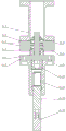
进一步的,所述的压头组件包括固定座,轴承座,深沟球轴承,大轴承调整环,小轴承调整环,推力滚针轴承,连接座,精密U型螺帽,压头座,压头,弹簧,调节螺丝,接触头;其中固定座安装在下压组件下面;轴承座安装于固定座的底部,轴承座内部安装有2个深沟球轴承和1个推力滚针轴承,2个深沟球轴承之间设有小轴承调整环,位于底部的深沟球轴承和推力滚针轴承之间设有大轴承调整环;连接座穿过2个深沟球轴承和1个推力滚针轴承安装于轴承座的底部,压头座通过螺钉固定于连接座的下表面,压头座的内部设有调节螺丝;压头安装于压头座底部的开口中,压头内部装有弹簧,压头前端装有非金属材质的接触头。Further, the indenter assembly includes a fixed seat, a bearing seat, a deep groove ball bearing, a large bearing adjustment ring, a small bearing adjustment ring, a thrust needle roller bearing, a connecting seat, a precision U-shaped nut, an indenter seat, a pressure head, spring, adjusting screw, contact head; the fixed seat is installed under the pressing component; the bearing seat is installed at the bottom of the fixed seat, and 2 deep groove ball bearings and 1 thrust needle roller bearing are installed inside the bearing seat, 2 deep groove ball bearings There is a small bearing adjustment ring between the groove ball bearings, and a large bearing adjustment ring between the deep groove ball bearing and the thrust needle roller bearing at the bottom; the connecting seat passes through 2 deep groove ball bearings and 1 thrust needle roller bearing Installed at the bottom of the bearing seat, the indenter seat is fixed on the lower surface of the connection seat by screws, and the inside of the indenter seat is provided with adjustment screws; The front end of the head is equipped with a contact head made of non-metallic material.
进一步的,所述的下压组件包括导向轴支座,导向柱,下压板,带法兰直线轴承,顶板,气缸,气缸连接头,浮动座,抱箍,缓冲垫;其中顶板安装于下压板的上表面,气缸安装于顶板的中心,其底部的气缸连接头通过浮动座安装于下压板的上表面;下压板的左右两侧分别安装1根导向柱,每根导向柱的底部设有导向轴支座,,每根导向柱的顶部通过带法兰直线轴承安装于顶板的下表面,下压板通过带法兰直线轴承与导向柱形成滑动装配,保证下压机构的顺畅运行,并通过固定在顶板上的气缸实现机构上下运动;每根导向柱的中部设有1组抱箍和缓冲垫。Further, the lower pressure assembly includes a guide shaft support, a guide column, a lower pressure plate, a flanged linear bearing, a top plate, a cylinder, a cylinder connector, a floating seat, a hoop, and a buffer pad; wherein the top plate is installed on the lower pressure plate. The cylinder is installed on the center of the top plate, and the cylinder connector at the bottom is installed on the upper surface of the lower pressure plate through the floating seat; a guide column is installed on the left and right sides of the lower pressure plate, and the bottom of each guide column is provided with a guide The shaft support, the top of each guide column is installed on the lower surface of the top plate through the flanged linear bearing, and the lower pressure plate forms a sliding assembly with the guide column through the flanged linear bearing to ensure the smooth operation of the lowering mechanism, and is fixed by fixing The cylinder on the top plate realizes the mechanism to move up and down; the middle of each guide column is provided with a set of hoop and cushion.
与现有技术相比,本发明的优点在于:Compared with the prior art, the advantages of the present invention are:
1)采用该机构的整个测量过程无人员参与,实现自动检测判断,自动化程度高,可以配合流水线使用,兼容性强,应用范围广;1) The entire measurement process of this mechanism is used without human participation, realizing automatic detection and judgment, with a high degree of automation, which can be used in conjunction with the assembly line, with strong compatibility and wide application range;
2)整套机构采用高精度接触式传感器,实现自动检测判断,排除人为因素干扰,提高测量精度;2) The whole set of mechanism adopts high-precision contact sensor to realize automatic detection and judgment, eliminate the interference of human factors, and improve the measurement accuracy;
3)采用人机分离理念,人工操作过程和设备检测分开,有效保证人员安全;3) The concept of man-machine separation is adopted, and the manual operation process and equipment detection are separated to effectively ensure the safety of personnel;
4)采用双工位设计理念,可以同步进行上下料和测试,有效提升生产效率;4) Using the dual-station design concept, it can simultaneously carry out loading and unloading and testing, effectively improving production efficiency;
5)采用高精度冲子成型机,可以实现快速装夹,满足多品种产品需求,兼容性强。5) Using high-precision punch forming machine, it can realize fast clamping, meet the needs of various products, and has strong compatibility.
附图说明Description of drawings
附图1是本发明一种吸盘跳动量自动检测结构示意图。FIG. 1 is a schematic structural diagram of the automatic detection of the jumping amount of a suction cup according to the present invention.
附图2是固定座组件结构示意图。Figure 2 is a schematic diagram of the structure of the fixed seat assembly.
附图3是定位座组件结构示意图。Figure 3 is a schematic diagram of the structure of the positioning seat assembly.
附图4是位移传感器组件结构示意图。Figure 4 is a schematic diagram of the structure of the displacement sensor assembly.
附图5是治具台升降组件结构示意图。FIG. 5 is a schematic diagram of the structure of the jig table lifting assembly.
附图6是治具台旋转组件结构示意图。FIG. 6 is a schematic view of the structure of the jig table rotating assembly.
附图7是压头组件结构示意图。Figure 7 is a schematic diagram of the structure of the indenter assembly.
附图8是下压组件结构示意图。FIG. 8 is a schematic diagram of the structure of the pressing down assembly.
其中1是固定座组件,2是定位座组件,3是位移传感器组件, 4是治具台升降组件,5是治具台旋转组件,6是压头组件,7是下压移栽组件;1-1是底座板,1-2是定位连接板,1-3是导向铜套,1-4是台阶定位销,1-5是拆换把手;2-1是底板,2-2是连接板,2-3是定位板,2-4是台阶定位销,2-5是导向铜套,2-6是安装连板,2-7是安装底板,2-8是定位条,2-9是成型器安装板,2-10是支撑筋板,2-11是电动筒夹式成型器,2-12是拆换把手;3-1是气缸固定板,3-2是气动滑台缸,3-3是气缸连接板,3-4是传感器固定块,3-5是位移传感器,3-6是调节块,3-7是调节螺丝座,3-8是调节螺丝;4-1是双轴气缸,4-2是气缸固定板,4-3是大支撑柱,4-4是连接板,4-5是连接柱,4-6是浮动接头,4-7是气缸连接板,4-8是小支撑柱,4-9是带法兰直线轴承,4-10是摆动平台固定板; 5-1是摆动平台,5-2是治具底板,5-3是产品治具;6-1是固定座,6-2是轴承座,6-3是深沟球轴承,6-4是大轴承调整环,6-5是小轴承调整环,6-6是推力滚针轴承,6-7是连接座,6-8是精密U型螺帽,6-9是压头座,6-10是压头,6-11是弹簧,6-12是调节螺丝,6-13是接触头;7-1是导向轴支座,7-2是导向柱,7-3是下压板,7-4是带法兰直线轴承,7-5是顶板,7-6是气缸,气9-7是缸连接头,7-8是浮动座,7-9是抱箍,7-10是缓冲垫。1 is the fixed seat assembly, 2 is the positioning seat assembly, 3 is the displacement sensor assembly, 4 is the jig table lifting assembly, 5 is the jig table rotating assembly, 6 is the indenter assembly, 7 is the downward pressure transplanting assembly; 1 -1 is the base plate, 1-2 is the positioning connection plate, 1-3 is the guide copper sleeve, 1-4 is the step positioning pin, 1-5 is the replacement handle; 2-1 is the bottom plate, 2-2 is the connection plate , 2-3 is the positioning plate, 2-4 is the step positioning pin, 2-5 is the guide copper sleeve, 2-6 is the installation connecting plate, 2-7 is the installation bottom plate, 2-8 is the positioning strip, 2-9 is the Former mounting plate, 2-10 is the support rib plate, 2-11 is the electric collet former, 2-12 is the dismantling handle; 3-1 is the cylinder fixing plate, 3-2 is the pneumatic slide cylinder, 3 -3 is the cylinder connecting plate, 3-4 is the sensor fixing block, 3-5 is the displacement sensor, 3-6 is the adjusting block, 3-7 is the adjusting screw seat, 3-8 is the adjusting screw; 4-1 is the double shaft Cylinder, 4-2 is the cylinder fixing plate, 4-3 is the large support column, 4-4 is the connecting plate, 4-5 is the connecting column, 4-6 is the floating joint, 4-7 is the cylinder connecting plate, 4-8 It is a small support column, 4-9 is a linear bearing with flange, 4-10 is the fixed plate of the swing platform; 5-1 is the swing platform, 5-2 is the base plate of the fixture, 5-3 is the product fixture; 6-1 is a fixed seat, 6-2 is a bearing seat, 6-3 is a deep groove ball bearing, 6-4 is a large bearing adjusting ring, 6-5 is a small bearing adjusting ring, 6-6 is a thrust needle roller bearing, 6-7 is the connecting seat, 6-8 is the precision U-shaped nut, 6-9 is the indenter seat, 6-10 is the indenter, 6-11 is the spring, 6-12 is the adjusting screw, 6-13 is the contact head; 7 -1 is the guide shaft support, 7-2 is the guide column, 7-3 is the lower pressure plate, 7-4 is the linear bearing with flange, 7-5 is the top plate, 7-6 is the cylinder, and 9-7 is the cylinder Connector, 7-8 is the floating seat, 7-9 is the hoop, 7-10 is the buffer.
具体实施方式Detailed ways
下面结合附图进一步说明本发明的技术方案。所述实施例的示例在附图中示出,其中自始至终相同或类似的标号表示相同或类似的元件或具有相同或类似功能的元件。下面通过参考附图描述的实施例是示例性的,旨在用于解释本发明,而不能理解为对本发明的限制。The technical solutions of the present invention are further described below with reference to the accompanying drawings. Examples of such embodiments are illustrated in the accompanying drawings, wherein the same or similar reference numerals refer to the same or similar elements or elements having the same or similar functions throughout. The embodiments described below with reference to the accompanying drawings are exemplary, and are intended to explain the present invention and should not be construed as limiting the present invention.
在本发明的描述中,需要理解的是,术语“中心”“纵向”“横向”“上”“下”“前”“后”“左”“右”“竖直”“水平”“顶”“底”“内”“外”“顺时针”“逆时针”等指示的方位或位置关系为基于附图所示的方位或位置关系,仅是为了便于描述本发明和简化描述,而不是指示或暗示所指的装置或元件必须具有特定的方位以特定的方位构造和操作,因此不能理解为对本发明的限制。In the description of the present invention, it should be understood that the terms "center", "portrait", "horizontal", "top", "bottom", "front", "rear", "left", "right", "vertical", "horizontal" and "top" The orientation or positional relationship indicated by "bottom", "inside", "outside", "clockwise", "counterclockwise", etc. is based on the orientation or positional relationship shown in the accompanying drawings, and is only for the convenience of describing the present invention and simplifying the description, rather than indicating Or imply that the referred device or element must have a specific orientation to be constructed and operated in a specific orientation, and therefore should not be construed as a limitation of the present invention.
在本发明中,除非另有明确的规定和限定,术语“安装”“相连”“连接”“固定”等术语应做广义理解,例如,可以是固定连接,也可以是可拆卸连接,或成一体;可以是直接相连,也可以通过中间媒介间接相连,可以是两个元件内部的连通或两个元件的相互作用关系。对于本领域的普通技术人员而言,可以根据具体情况理解上述术语在本发明中的具体含义。In the present invention, unless otherwise expressly specified and limited, the terms "installed", "connected", "connected" and "fixed" should be understood in a broad sense, for example, it may be a fixed connection, a detachable connection, or a fixed connection. Integral; it can be directly connected, or indirectly connected through an intermediate medium, and it can be the internal connection of two elements or the interaction relationship between the two elements. For those of ordinary skill in the art, the specific meanings of the above terms in the present invention can be understood according to specific situations.
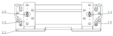
如图1所示的一种汽车压缩机用的双工位吸盘跳动量检测机构,其结构包括固定座组件1,定位座组件2,位移传感器组件3,治具台升降组件4,治具台旋转组件5,压头组件6,下压组件7;其中固定座组件1和定位座组件2的边缘互相连接并固定,下压组件7安装于定位座组件2的上表面,压头组件6安装于下压组件7的中部下方,位移传感器组件3安装于压头组件6下方定位座组件2上表面的一侧;治具台升降组件4安装于固定座组件1的下表面,治具台旋转组件5安装于治具台升降组件4的顶部。As shown in Figure 1, a double-station suction cup runout detection mechanism for an automobile compressor, its structure includes a fixed seat assembly 1, a positioning seat assembly 2, a displacement sensor assembly 3, a jig table lift assembly 4, a jig table Rotating assembly 5, pressing head assembly 6, pressing down assembly 7; wherein the edges of the fixed seat assembly 1 and the positioning seat assembly 2 are connected and fixed to each other, the pressing down assembly 7 is installed on the upper surface of the positioning seat assembly 2, and the pressing head assembly 6 is installed Below the middle of the pressing component 7, the displacement sensor component 3 is installed on one side of the upper surface of the positioning seat component 2 below the pressing head component 6; the fixture table lifting component 4 is installed on the lower surface of the fixed seat component 1, and the fixture table rotates The assembly 5 is installed on the top of the jig table lifting assembly 4 .
如图2所示,所述的固定座组件1位于整体机构的前端,包括底座板1-1,定位连接板1-2,导向铜套1-3,台阶定位销1-4,拆换把手1-5;其中底座板1-1的中部设有方形通孔,底座板1-1的左右两侧分别对称设有1个拆换把手1-5,维修保养机构时,提高工作效率,方便快捷;2块定位连接板1-2对称设于底座板1-1的的上表面,每块定位连接板1-2的表面设有1个导向套1-3,每个导向套1-3与其下方底座板1-1上设置的台阶定位销1-4相组合,利用导向套1-3和台阶定位销1-4间的公差配合,使定位连接板1-2精准固定在底座板1-1上,治具台升降组件5的连接柱5-5固定在定位连接板1-2下面时,可保证治具台升降机构5的位置精度。所述的导向铜套1-3优选的是怡合达品牌,优选型号为OFG61-D12-L20。所述的台阶定位销1-4优选的是怡合达品牌,优选型号为YFF21-D8-P12。As shown in Figure 2, the fixed seat assembly 1 is located at the front end of the overall mechanism, including a base plate 1-1, a positioning connecting plate 1-2, a guide copper sleeve 1-3, a step positioning pin 1-4, a handle for disassembly and replacement 1-5; The center of the base plate 1-1 is provided with a square through hole, and the left and right sides of the base plate 1-1 are symmetrically provided with a dismantling handle 1-5, which improves work efficiency and facilitates maintenance of the mechanism. Fast; two positioning connecting plates 1-2 are symmetrically arranged on the upper surface of the base plate 1-1, and one guiding sleeve 1-3 is arranged on the surface of each positioning connecting plate 1-2, and each guiding sleeve 1-3 Combined with the step positioning pins 1-4 set on the base plate 1-1 below it, and using the tolerance between the guide sleeve 1-3 and the step positioning pins 1-4, the positioning connecting plate 1-2 is accurately fixed on the base plate 1. On -1, when the connecting column 5-5 of the jig table lifting assembly 5 is fixed under the positioning connecting plate 1-2, the positional accuracy of the jig table lifting mechanism 5 can be guaranteed. The guide copper sleeves 1-3 are preferably Yiheda brand, and the preferred model is OFG61-D12-L20. The step positioning pins 1-4 are preferably Yiheda brand, and the preferred model is YFF21-D8-P12.
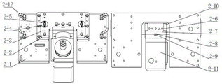
如图3所示,所述的定位座组件2位于整体机构的后端,包括底板2-1,连接板2-2,定位板2-3,台阶定位销2-4,导向铜套2-5,安装连板2-6,安装底板2-7,定位条2-8,成型器安装板2-9,支撑筋板2-10,冲子成型器2-11,拆换把手2-12;其中底板2-1的左右两侧对称设有1对拆换把手2-12,底板2-1的中部设有凹槽,凹槽两侧对称设有1对台阶定位销2-4,;定位板2-3通过设于其表面的1对导向铜套2-5安装在底板2-1的上表面,利用台阶定位销2-4和导向铜套2-5间的公差配合,使定位板2-3精准固定在连接板2-2上;安装连板2-6的一端通过通过定位销和螺丝固定于定位板2-3上,支撑筋板2-10设于安装连板2-6的两侧;安装底板2-7通过定位销和螺丝固定于安装连板2-6上,定位条2-8固定在安装底板2-7上,成型器安装板2-9通过与定位条2-8配合,精准固定在安装底板2-7上,冲子成型器2-11固定在成型器安装板2-9的前端。治具台升降组件5通过运行至下位时,工作位治具7-3把产品放至冲子成型器2-11上,冲子成型器2-11可精准夹持产品并且夹持时能自动对准中心,夹持精度可保证在0.01mm以内,目前常规检测方式的精度最低只能达到0.03mm,新方式提升了夹持精度,从而保证了产品检测结果的准确性;目前常规测试方式只能测试单一产品,本发明采用冲子成型器2-11时利用夹头夹持产品,可夹持多种产品,机构的兼容性强,且成型器自带电机旋转测试产品并且速度可调,无需增加旋转机构。所述的导向铜套1-3优选的是怡合达品牌,优选型号为OFG61-D12-L20。所述的台阶定位销1-4优选的是怡合达品牌,优选型号为YFF21-D8-P12。所述的冲子成型器优选的是台湾精展品牌,优选型号为51260-16-220。As shown in Figure 3, the positioning seat assembly 2 is located at the rear end of the overall mechanism, including a bottom plate 2-1, a connecting plate 2-2, a positioning plate 2-3, a step positioning pin 2-4, and a guide copper sleeve 2- 5. Install connecting plate 2-6, install bottom plate 2-7, positioning strip 2-8, former mounting plate 2-9, support rib plate 2-10, punch former 2-11, remove and replace handle 2-12 ; The left and right sides of the bottom plate 2-1 are symmetrically provided with a pair of dismantling handles 2-12, the middle of the bottom plate 2-1 is provided with a groove, and a pair of step positioning pins 2-4 are symmetrically provided on both sides of the groove; The positioning plate 2-3 is installed on the upper surface of the base plate 2-1 through a pair of guide copper sleeves 2-5 arranged on its surface, and the tolerance between the step positioning pins 2-4 and the guide copper sleeves 2-5 is used to make the positioning The plate 2-3 is precisely fixed on the connecting plate 2-2; one end of the mounting connecting plate 2-6 is fixed on the positioning plate 2-3 through positioning pins and screws, and the supporting rib plate 2-10 is arranged on the mounting connecting plate 2- 6 on both sides; the mounting base plate 2-7 is fixed on the mounting connecting plate 2-6 by positioning pins and screws, the positioning strip 2-8 is fixed on the mounting base plate 2-7, and the former mounting plate 2-9 passes through the positioning strip. 2-8 is matched, and is precisely fixed on the mounting base plate 2-7, and the punch former 2-11 is fixed on the front end of the former mounting plate 2-9. When the jig table lift assembly 5 is moved to the lower position, the working position jig 7-3 puts the product on the punch former 2-11, and the punch former 2-11 can precisely clamp the product and can automatically clamp the product. Aiming at the center, the clamping accuracy can be guaranteed to be within 0.01mm. At present, the minimum accuracy of the conventional testing method can only reach 0.03mm. The new method improves the clamping accuracy, thus ensuring the accuracy of the product testing results; the current conventional testing method only A single product can be tested. When the punch former 2-11 is used in the present invention, the product is clamped by a chuck, which can clamp a variety of products. The mechanism has strong compatibility, and the former has a motor to rotate the test product and the speed is adjustable. No need to add a rotating mechanism. The guide copper sleeves 1-3 are preferably Yiheda brand, and the preferred model is OFG61-D12-L20. The step positioning pins 1-4 are preferably Yiheda brand, and the preferred model is YFF21-D8-P12. The punch former is preferably the Taiwan Jingzhan brand, and the preferred model is 51260-16-220.
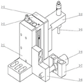
如图4所示,所述的位移传感器组件3包括气缸固定板3-1,气动滑台缸3-2,气缸连接板3-3,传感器固定块3-4,位移传感器3-5,调节块3-6,调节螺丝座3-7,调节螺丝3-8;其中气缸固定板3-1竖直固定于底板2-1上凹槽的一侧,主要用于测量工作位产品的跳动量;气动滑台缸3-2安装于气缸固定板3-1的右侧表面,气缸连接板3-3安装于气动滑台缸3-2的右侧表面,传感器固定块3-4安装于气缸连接板3-3的右侧表面,位移传感器3-5安装于传感器固定块3-4的端部;调节螺丝座3-7设于气动滑台缸3-2的前方,其内部设有调节螺丝3-8,调节螺丝3-8的末端通过调节块3-6连接气缸固定板3-1。利用气动滑台缸3-2的行程可调特点,进而调整位移传感器3-5所在高度,同时利用调节螺丝3-8调整气缸固定板3-1的前后位置,进而调整位移传感器3-5离检测中心为的距离,达到适应不同规格产品的功能,位移传感器3-5为直接测量产品跳动量的传感器。所述的气动滑台缸3-2优选的是日本SMC品牌,优选型号为MXS6-20A-M9B。所述的位移传感器3-5优选的是美国基恩士品牌,优选型号是GT2-S1。As shown in FIG. 4 , the displacement sensor assembly 3 includes a cylinder fixing plate 3-1, a pneumatic slide cylinder 3-2, a cylinder connecting plate 3-3, a sensor fixing block 3-4, a displacement sensor 3-5, an adjustment Block 3-6, adjusting screw seat 3-7, adjusting screw 3-8; the cylinder fixing plate 3-1 is vertically fixed to one side of the groove on the bottom plate 2-1, mainly used to measure the runout of the work position product ;Pneumatic sliding table cylinder 3-2 is installed on the right side surface of cylinder fixing plate 3-1, cylinder connecting plate 3-3 is installed on the right side surface of pneumatic sliding table cylinder 3-2, sensor fixing block 3-4 is installed on the cylinder On the right side surface of the connecting plate 3-3, the displacement sensor 3-5 is installed on the end of the sensor fixing block 3-4; the adjusting screw seat 3-7 is arranged in front of the pneumatic slide cylinder 3-2, and there is an adjusting screw seat inside. Screw 3-8, the end of the adjusting screw 3-8 is connected to the cylinder fixing plate 3-1 through the adjusting block 3-6. Use the adjustable stroke of the pneumatic slide cylinder 3-2 to adjust the height of the displacement sensor 3-5. At the same time, use the adjustment screw 3-8 to adjust the front and rear positions of the cylinder fixing plate 3-1, and then adjust the distance of the displacement sensor 3-5. The distance between the detection center is to achieve the function of adapting to products of different specifications. Displacement sensors 3-5 are sensors that directly measure the amount of product runout. The pneumatic slide cylinder 3-2 is preferably the Japanese SMC brand, and the preferred model is MXS6-20A-M9B. The displacement sensors 3-5 are preferably the American KEYENCE brand, and the preferred model is GT2-S1.
如图5所示,所述的治具升降组件4位于固定座组件1的正下方,其结构包括双轴气缸4-1,气缸固定板4-2,大支撑柱4-3,连接板4-4,连接柱4-5,浮动接头4-6,气缸连接板4-7,小支撑柱4-8,带法兰直线轴承4-9,摆动平台固定板4-10;其中4根连接柱4-5固定在底座板1-1的下表面,并同时与连接板4-4的四个角落相固定,连接板4-4的上表面设有摆动平台固定板4-10;气缸连接板4-7通过4根小支撑柱4-8固定于连接板4-4的下表面,每根小支撑柱4-8与连接板4-4的的连接处均设有带法兰直线轴承4-9;气缸连接板4-7的下表面中心通过浮动接头4-6连接气缸固定板4-2的上表面中心,气缸固定板4-2的上表面四个角落分别安装1根大支撑柱4-3,大支撑柱4-3的顶端与连接板4-4的下表面连接;双轴气缸4-1安装于气缸固定板4-2的下表面中心。采用双轴气缸4-1作为升降组件动力,通过双轴气缸4-1的升降,带动摆动平台固定板4-10跟随升降,继而控制治具台旋转组件5的升降。其中双轴气缸连接时采用浮动接头4-6连接,升降组件均采用标准光轴及米思米的带法兰直线轴承,这样就保证了机构升降运行顺畅无卡顿。通过治具升降组件4的顶升,保证了治具台旋转组件5能顺利旋转,切换工作位与上料位,当位置切换完成后,升降机构运行至下位,此时工作位上的产品便可落至电动筒夹式成型器2-11上。所述的双轴气缸4-1优选的是台湾亚德客品牌,优选型号为SUJ40X80-10S。所述的浮动接头4-6优选的是台湾亚德客品牌,优选型号为F-M12X125F。所述的带法兰直线轴承4-9优选的是日本米思米品牌,优选型号为C-LHFS20。As shown in FIG. 5 , the jig lifting assembly 4 is located directly below the fixing seat assembly 1, and its structure includes a double-shaft cylinder 4-1, a cylinder fixing plate 4-2, a large support column 4-3, and a connecting plate 4 -4, connecting column 4-5, floating joint 4-6, cylinder connecting plate 4-7, small support column 4-8, flanged linear bearing 4-9, swing platform fixing plate 4-10; 4 of them are connected The column 4-5 is fixed on the lower surface of the base plate 1-1, and at the same time is fixed with the four corners of the connecting plate 4-4. The upper surface of the connecting plate 4-4 is provided with a swing platform fixing plate 4-10; The plate 4-7 is fixed on the lower surface of the connecting plate 4-4 through 4 small supporting columns 4-8, and the connection between each small supporting column 4-8 and the connecting plate 4-4 is provided with a flanged linear bearing 4-9; The center of the lower surface of the cylinder connecting plate 4-7 is connected to the center of the upper surface of the cylinder fixing plate 4-2 through the floating joint 4-6, and a large support is installed on the four corners of the upper surface of the cylinder fixing plate 4-2. The top of the column 4-3 and the large support column 4-3 is connected with the lower surface of the connecting plate 4-4; the biaxial cylinder 4-1 is installed on the center of the lower surface of the cylinder fixing plate 4-2. The dual-axis cylinder 4-1 is used as the power for the lifting assembly. The lifting and lowering of the dual-axis cylinder 4-1 drives the swing platform fixing plate 4-10 to follow the lifting, and then controls the lifting and lowering of the fixture table rotating assembly 5. Among them, the floating joint 4-6 is used for the connection of the double-axis cylinder, and the lifting components use standard optical shafts and Misimi's flanged linear bearings, so as to ensure the smooth lifting of the mechanism without jamming. The lifting of the jig lifting assembly 4 ensures that the jig table rotating assembly 5 can rotate smoothly to switch the working position and the feeding position. When the position switching is completed, the lifting mechanism runs to the lower position, and the products on the working position are Can be dropped onto electric collet former 2-11. The double-shaft cylinder 4-1 is preferably a Taiwan AirTAC brand, and the preferred model is SUJ40X80-10S. The floating joints 4-6 are preferably made of the Taiwan AirTAC brand, and the preferred model is F-M12X125F. The flanged linear bearing 4-9 is preferably the Japanese Misimi brand, and the preferred model is C-LHFS20.
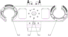
如图6所示,所述的治具台旋转组件5包括摆动平台5-1,治具底板5-2,产品治具5-3;其中摆动平台5-1的底部固定在摆动平台固定板4-10的上表面,摆动平台5-1的中心设有旋转气缸,治具底板5-2固定在旋转气缸上,2组产品治具5-3以旋转气缸为中心对称安装于治具底板5-2的两侧。两个产品治具5-3分别固定在治具底板5-2的两端,形成上料位和工作位,并通过摆动平台进行180°的旋转切换,这样实现了上下料位和测试位的分离,保证了人工上下料的安全性,减少检测过程的不确定性,增加了检测精度,并且上下料和产品检测可以同步进行,从上料到检测完成这个过程缩短至6S;和现有手工检测相比,生产效率提升了一倍。所述的摆动平台5-1优选的是日本SMC品牌,优选型号为MSQB70A。As shown in FIG. 6 , the jig table rotating assembly 5 includes a swing platform 5-1, a jig base plate 5-2, and a product jig 5-3; wherein the bottom of the swing platform 5-1 is fixed on the swing platform fixing plate On the upper surface of 4-10, the center of the swing platform 5-1 is provided with a rotating cylinder, the fixture base plate 5-2 is fixed on the rotating cylinder, and the two sets of product fixtures 5-3 are symmetrically installed on the fixture base plate with the rotating cylinder as the center 5-2 sides. The two product jigs 5-3 are respectively fixed on the two ends of the jig base plate 5-2 to form the upper material level and the working level, and the 180° rotation switch is performed through the swing platform, which realizes the upper and lower material level and the test level. The separation ensures the safety of manual loading and unloading, reduces the uncertainty of the detection process, and increases the detection accuracy, and the loading and unloading and product testing can be carried out simultaneously, and the process from loading to testing is shortened to 6S; and the existing manual Compared with inspection, the production efficiency has been doubled. Described swing platform 5-1 is preferably Japanese SMC brand, and the preferred model is MSQB70A.
如图7所示,所述的压头组件6包括固定座6-1,轴承座6-2,深沟球轴承6-3,大轴承调整环6-4,小轴承调整环6-5,推力滚针轴承6-6,连接座6-7,精密U型螺帽6-8,压头座6-9,压头6-10,弹簧6-11,调节螺丝6-12,接触头6-13;其中固定座6-1安装在下压组件7下面,主要用于固定工作位需要测试的产品;轴承座6-2安装于固定座6-1的底部,轴承座6-2内部安装有2个深沟球轴承6-3和1个推力滚针轴承6-6,2个深沟球轴承6-3之间设有小轴承调整环6-5,位于底部的深沟球轴承6-3和推力滚针轴承6-6之间设有大轴承调整环6-4,使组件可以承受径向负载和承受轴向负载;连接座6-7穿过2个深沟球轴承6-3和1个推力滚针轴承6-6安装于轴承座6-2的底部,压头座6-9通过螺钉固定于连接座6-7的下表面,压头座6-9的内部设有调节螺丝6-12;压头6-10安装于压头座6-9底部的开口中,压头6-10内部装有弹簧6-11,起到缓冲作用,压头6-10前端装有非金属材质的接触头6-13。当电动筒夹式成型器2-11带动测试位产品转动开始测试时,下压机构在固定产品时不会伤到测试产品,保护测试产品。所述的深沟球轴承6-3优选的是日本米思米品牌,优选型号为B6900ZZ。所述的大轴承调整环6-4优选的是日本米思米品牌,优选型号为CLBSM17-22-2.0。所述的小轴承调整环6-5优选的是日本米思米品牌,优选型号为CLBUM10-14-4.0。所述的推力滚针轴承6-6优选的是日本IKO品牌,优选型号为AZ10249。所述的精密U型螺帽6-8优选的是日本米思米品牌,优选型号为FUNT10。所述的弹簧6-11优选的是怡合达品牌,优选型号为YUR-D13-L35。As shown in Figure 7, the indenter assembly 6 includes a fixed seat 6-1, a bearing seat 6-2, a deep groove ball bearing 6-3, a large bearing adjustment ring 6-4, a small bearing adjustment ring 6-5, Thrust needle roller bearing 6-6, connecting seat 6-7, precision U-shaped nut 6-8, indenter seat 6-9, indenter 6-10, spring 6-11, adjusting screw 6-12, contact head 6 -13; The fixed seat 6-1 is installed under the pressing component 7, and is mainly used to fix the products that need to be tested at the working position; the bearing seat 6-2 is installed at the bottom of the fixed seat 6-1, and the inside of the bearing seat 6-2 is installed 2 deep groove ball bearings 6-3 and 1 thrust needle roller bearing 6-6, between the 2 deep groove ball bearings 6-3 there is a small bearing adjusting ring 6-5, the deep groove ball bearing at the bottom 6- 3 A large bearing adjusting ring 6-4 is arranged between the thrust needle roller bearing 6-6, so that the assembly can bear radial load and axial load; the connecting seat 6-7 passes through 2 deep groove ball bearings 6-3 And a thrust needle roller bearing 6-6 is installed on the bottom of the bearing seat 6-2, the indenter seat 6-9 is fixed on the lower surface of the connecting seat 6-7 by screws, and the inner part of the indenter seat 6-9 is provided with adjustment Screws 6-12; the indenter 6-10 is installed in the opening at the bottom of the indenter seat 6-9, the indenter 6-10 is equipped with a spring 6-11 inside, which plays a buffering role, and the front end of the indenter 6-10 is equipped with a non- Metal contacts 6-13. When the electric collet former 2-11 drives the test position product to rotate to start the test, the pressing mechanism will not hurt the test product when fixing the product, and protect the test product. The deep groove ball bearing 6-3 is preferably the Japanese Misimi brand, and the preferred model is B6900ZZ. The said large bearing adjustment ring 6-4 is preferably the Japanese Misimi brand, and the preferred model is CLBSM17-22-2.0. Said small bearing adjustment ring 6-5 is preferably the Japanese Misimi brand, and the preferred model is CLBUM10-14-4.0. The thrust needle roller bearings 6-6 are preferably Japanese IKO brand, and the preferred model is AZ10249. The precision U-shaped nuts 6-8 are preferably the Japanese Misimi brand, and the preferred model is FUNT10. The springs 6-11 are preferably Yiheda brand, and the preferred model is YUR-D13-L35.
如图8所示,所述的下压组件7包括导向轴支座7-1,导向柱7-2,下压板7-3,带法兰直线轴承7-4,顶板7-5,气缸7-6,气缸连接头7-7,浮动座7-8,抱箍7-9,缓冲垫7-10;其中顶板7-5安装于下压板7-3的上表面,气缸7-6安装于顶板7-5的中心,其底部的气缸连接头7-7通过浮动座7-8安装于下压板7-3的上表面;下压板7-3的左右两侧分别安装1根导向柱7-2,每根导向柱7-2的底部设有导向轴支座7-1,,每根导向柱7-2的顶部通过带法兰直线轴承7-4安装于顶板7-5的下表面,下压板7-3通过带法兰直线轴承7-4与导向柱7-2形成滑动装配,保证下压机构的顺畅运行,并通过固定在顶板7-5上的气缸7-6实现机构上下运动;,每根导向柱7-2的中部设有1组抱箍7-9和缓冲垫7-10,用于控制下压板7-3的下行位置,进而起到调整下压行程的作用,达到保护测试产品和兼容多种产品的功能。所述的带法兰直线轴承7-4优选的是日本米思米品牌,优选型号为C-LHFS40。所述的气缸7-6优选的是台湾亚德客品牌,优选型号为SU32X150S。所述的抱箍7-9优选的是日本米思米品牌,优选型号为SCD40。As shown in FIG. 8 , the lower pressing assembly 7 includes a guide shaft support 7-1, a guiding column 7-2, a lower pressing plate 7-3, a flanged linear bearing 7-4, a top plate 7-5, and a cylinder 7 -6, cylinder connector 7-7, floating seat 7-8, hoop 7-9, buffer pad 7-10; the top plate 7-5 is installed on the upper surface of the lower pressure plate 7-3, and the cylinder 7-6 is installed on the In the center of the top plate 7-5, the cylinder connector 7-7 at the bottom is installed on the upper surface of the lower pressing plate 7-3 through the floating seat 7-8; the left and right sides of the lower pressing plate 7-3 are respectively installed with a guide column 7- 2. The bottom of each guide column 7-2 is provided with a guide shaft support 7-1, and the top of each guide column 7-2 is installed on the lower surface of the top plate 7-5 through a flanged linear bearing 7-4, The lower pressing plate 7-3 forms a sliding assembly with the guide column 7-2 through the flanged linear bearing 7-4 to ensure the smooth operation of the pressing mechanism, and the up and down movement of the mechanism is realized by the cylinder 7-6 fixed on the top plate 7-5 ;, the middle of each guide column 7-2 is provided with a group of hoop 7-9 and a buffer pad 7-10, which are used to control the downward position of the lower pressing plate 7-3, and then play the role of adjusting the downward pressing stroke to achieve Protects tested products and features compatible with multiple products. The flanged linear bearing 7-4 is preferably the Japanese Misimi brand, and the preferred model is C-LHFS40. The cylinders 7-6 are preferably made of the Taiwan AirTAC brand, and the preferred model is SU32X150S. Described hoop 7-9 is preferably Japanese Misumi brand, and the preferred model is SCD40.
本发明所提出的一种双工位吸盘跳动量自动检测机构,结构合理;整个检测过程无需人员参与,易于和流水线对接,实现在线检测;操作简单安全,减少操作重复劳动强度;整个检测过程自动完成,排除人为因素影响;利用冲子成型器夹持产品,夹持精度控制在0.01mm以内,且兼容性强;采用高精度位移传感器,传感器检测精度可达到1μm,有效保证了检测精度和产品质量;本测试机构采用双工位工作,利用摆动平台旋转180°的特性实现上下料和产品检测位分离,既可大幅度提升生产效率又保证了人工操作的安全性。综上,本发明有结构合理,操作简单安全,测试精度高且稳定,生产效率高等优点。The double-station suction cup runout automatic detection mechanism proposed by the invention has a reasonable structure; the whole detection process does not require personnel to participate, and is easy to connect with the assembly line to realize online detection; the operation is simple and safe, and the repetitive labor intensity of the operation is reduced; the whole detection process is automatic Completed, eliminating the influence of human factors; using a punch former to clamp the product, the clamping accuracy is controlled within 0.01mm, and the compatibility is strong; using a high-precision displacement sensor, the sensor detection accuracy can reach 1μm, effectively ensuring the detection accuracy and product. Quality; this testing mechanism adopts double-station work, and utilizes the characteristics of 180° rotation of the oscillating platform to realize the separation of loading and unloading and product detection position, which can greatly improve the production efficiency and ensure the safety of manual operation. To sum up, the present invention has the advantages of reasonable structure, simple and safe operation, high and stable testing accuracy, and high production efficiency.
以上所述仅为本发明的实施例,并非以此限制本发明的保护范围,凡是利用本说明书及附图内容所作的等效结构或等效流程变换,或直接或间接运用在其他相关的技术领域,均同理包括在本发明的专利保护范围内。The above descriptions are only the embodiments of the present invention, and are not intended to limit the protection scope of the present invention. Any equivalent structure or equivalent process transformation made by using the contents of this specification and the accompanying drawings, or directly or indirectly applied to other related technologies Fields are similarly included in the scope of patent protection of the present invention.
Claims (8)
Priority Applications (1)
| Application Number | Priority Date | Filing Date | Title |
|---|---|---|---|
| CN202010817791.2A CN111854569A (en) | 2020-08-14 | 2020-08-14 | A double-station suction cup runout detection mechanism for automobile compressors |
Applications Claiming Priority (1)
| Application Number | Priority Date | Filing Date | Title |
|---|---|---|---|
| CN202010817791.2A CN111854569A (en) | 2020-08-14 | 2020-08-14 | A double-station suction cup runout detection mechanism for automobile compressors |
Publications (1)
| Publication Number | Publication Date |
|---|---|
| CN111854569A true CN111854569A (en) | 2020-10-30 |
Family
ID=72968635
Family Applications (1)
| Application Number | Title | Priority Date | Filing Date |
|---|---|---|---|
| CN202010817791.2A Pending CN111854569A (en) | 2020-08-14 | 2020-08-14 | A double-station suction cup runout detection mechanism for automobile compressors |
Country Status (1)
| Country | Link |
|---|---|
| CN (1) | CN111854569A (en) |
Cited By (1)
| Publication number | Priority date | Publication date | Assignee | Title |
|---|---|---|---|---|
| CN113937966A (en) * | 2021-09-13 | 2022-01-14 | 苏州新智机电科技有限公司 | A piece of motor stator connecting plate assembly mechanism |
Citations (6)
| Publication number | Priority date | Publication date | Assignee | Title |
|---|---|---|---|---|
| CN208432660U (en) * | 2018-06-07 | 2019-01-25 | 深圳市佳德和科技有限公司 | A kind of resistance detection mechanism |
| CN109282749A (en) * | 2018-11-14 | 2019-01-29 | 南京林业大学 | A kind of hub detection device |
| CN109443282A (en) * | 2018-12-27 | 2019-03-08 | 宁波中亿自动化装备有限公司 | Bearing inner race raceway diameter detection device |
| CN110530275A (en) * | 2019-08-14 | 2019-12-03 | 瑞斯恩智能科技(苏州)有限公司 | A kind of outer diameter and glitch detection machine |
| US20200124510A1 (en) * | 2016-07-08 | 2020-04-23 | Jilin University | System and method for in-situ testing of mechanical properties of materials in static and dynamic load spectra |
| CN214333570U (en) * | 2020-08-14 | 2021-10-01 | 苏州新智机电科技有限公司 | Double-station sucker runout amount detection mechanism for automobile compressor |
-
2020
- 2020-08-14 CN CN202010817791.2A patent/CN111854569A/en active Pending
Patent Citations (6)
| Publication number | Priority date | Publication date | Assignee | Title |
|---|---|---|---|---|
| US20200124510A1 (en) * | 2016-07-08 | 2020-04-23 | Jilin University | System and method for in-situ testing of mechanical properties of materials in static and dynamic load spectra |
| CN208432660U (en) * | 2018-06-07 | 2019-01-25 | 深圳市佳德和科技有限公司 | A kind of resistance detection mechanism |
| CN109282749A (en) * | 2018-11-14 | 2019-01-29 | 南京林业大学 | A kind of hub detection device |
| CN109443282A (en) * | 2018-12-27 | 2019-03-08 | 宁波中亿自动化装备有限公司 | Bearing inner race raceway diameter detection device |
| CN110530275A (en) * | 2019-08-14 | 2019-12-03 | 瑞斯恩智能科技(苏州)有限公司 | A kind of outer diameter and glitch detection machine |
| CN214333570U (en) * | 2020-08-14 | 2021-10-01 | 苏州新智机电科技有限公司 | Double-station sucker runout amount detection mechanism for automobile compressor |
Cited By (1)
| Publication number | Priority date | Publication date | Assignee | Title |
|---|---|---|---|---|
| CN113937966A (en) * | 2021-09-13 | 2022-01-14 | 苏州新智机电科技有限公司 | A piece of motor stator connecting plate assembly mechanism |
Similar Documents
| Publication | Publication Date | Title |
|---|---|---|
| CN108686982B (en) | Detection device and detection method for outer edge deformation of hub blank | |
| CN109975313B (en) | Automatic wheel detection device | |
| CN108554845B (en) | A device for online detection of wheel hub blank deformation | |
| CN201170723Y (en) | A vehicle wheel detection device based on CCD image technology | |
| CN104515493B (en) | Automatic radial run-out measuring device | |
| CN214333570U (en) | Double-station sucker runout amount detection mechanism for automobile compressor | |
| CN107627049B (en) | Be used for heat welding to detect Special heat welding device for equipment | |
| CN111854569A (en) | A double-station suction cup runout detection mechanism for automobile compressors | |
| CN107598194A (en) | A kind of machine tool chief axis running test platform that can simulate working condition | |
| CN213239285U (en) | A Drilling Device Based on Drilling Method for Rapid Calibration of Residual Stress Testing | |
| CN211601876U (en) | Micro-aperture measuring device | |
| CN209197613U (en) | A kind of special gauge for detection hole position degree | |
| CN208601388U (en) | A kind of vehicle cubing positioning compression device | |
| CN215338138U (en) | High-efficient ring flange axiality detection device | |
| CN117433470A (en) | Device and method for detecting inner diameter and outer diameter of bearing ring | |
| CN206281474U (en) | A kind of positioner for tube-like piece measurement | |
| CN113654444B (en) | Connecting device based on high-precision bearing ring checking fixture | |
| CN222013066U (en) | Height detection device for new energy automobile part finished product | |
| CN219121318U (en) | Bearing detects and marking device | |
| CN218885855U (en) | Hub bearing outer ring and shaft wheel flaw detection mechanism | |
| CN214264620U (en) | Micro motor assembling equipment | |
| CN217483415U (en) | Shaft hub assembly angle measuring instrument | |
| CN222104667U (en) | Automatic measuring device for workpiece size | |
| CN219015153U (en) | Clamping tool for positioning and detecting composite material special-shaped cylinder | |
| CN220829166U (en) | Motor core assembly detection mechanism |
Legal Events
| Date | Code | Title | Description |
|---|---|---|---|
| PB01 | Publication | ||
| PB01 | Publication | ||
| SE01 | Entry into force of request for substantive examination | ||
| SE01 | Entry into force of request for substantive examination |