CN111842300A - Mechanical shaft cleaning device - Google Patents
Mechanical shaft cleaning device Download PDFInfo
- Publication number
- CN111842300A CN111842300A CN202010734118.2A CN202010734118A CN111842300A CN 111842300 A CN111842300 A CN 111842300A CN 202010734118 A CN202010734118 A CN 202010734118A CN 111842300 A CN111842300 A CN 111842300A
- Authority
- CN
- China
- Prior art keywords
- wall
- arc
- outer walls
- electric
- mechanical shaft
- Prior art date
- Legal status (The legal status is an assumption and is not a legal conclusion. Google has not performed a legal analysis and makes no representation as to the accuracy of the status listed.)
- Withdrawn
Links
Images


Classifications
-
- B—PERFORMING OPERATIONS; TRANSPORTING
- B08—CLEANING
- B08B—CLEANING IN GENERAL; PREVENTION OF FOULING IN GENERAL
- B08B3/00—Cleaning by methods involving the use or presence of liquid or steam
- B08B3/02—Cleaning by the force of jets or sprays
-
- B—PERFORMING OPERATIONS; TRANSPORTING
- B08—CLEANING
- B08B—CLEANING IN GENERAL; PREVENTION OF FOULING IN GENERAL
- B08B13/00—Accessories or details of general applicability for machines or apparatus for cleaning
-
- B—PERFORMING OPERATIONS; TRANSPORTING
- B08—CLEANING
- B08B—CLEANING IN GENERAL; PREVENTION OF FOULING IN GENERAL
- B08B3/00—Cleaning by methods involving the use or presence of liquid or steam
- B08B3/04—Cleaning involving contact with liquid
- B08B3/10—Cleaning involving contact with liquid with additional treatment of the liquid or of the object being cleaned, e.g. by heat, by electricity or by vibration
- B08B3/12—Cleaning involving contact with liquid with additional treatment of the liquid or of the object being cleaned, e.g. by heat, by electricity or by vibration by sonic or ultrasonic vibrations
-
- B—PERFORMING OPERATIONS; TRANSPORTING
- B08—CLEANING
- B08B—CLEANING IN GENERAL; PREVENTION OF FOULING IN GENERAL
- B08B2203/00—Details of cleaning machines or methods involving the use or presence of liquid or steam
- B08B2203/02—Details of machines or methods for cleaning by the force of jets or sprays
- B08B2203/0258—Multiple lance high pressure cleaning station
Abstract
The invention belongs to the technical field of machining, and particularly relates to a mechanical shaft cleaning device, which aims at the problem that the existing cleaning device cannot sufficiently clean a mechanical shaft. According to the mechanical shaft cleaning device, the third electric guide rail, the second electric telescopic rod, the first arc-shaped supporting plate, the first electric telescopic rod and the arc-shaped water distribution pipe are arranged, the position of the arc-shaped water distribution pipe can be adjusted through the third electric sliding block and the second electric telescopic rod, the circumference of the mechanical shaft is washed through the water spray head, and the overall sufficiency of cleaning can be effectively improved through the wrapping type washing.
Description
Technical Field
The invention relates to the technical field of machining, in particular to a mechanical shaft cleaning device.
Background
Machining refers to a process of changing the physical dimensions or properties of a workpiece by a mechanical device. The difference in the machining method can be divided into cutting machining and pressing machining. The production process of a machine refers to the whole process of making a product from raw materials (or semi-finished products). For machine production, the raw material transportation and preservation, production preparation, blank manufacturing, part processing and heat treatment, product assembly and debugging, painting and packaging and the like are included.
In the process of machining the mechanical shaft, the surface of the mechanical shaft needs to be cleaned, and in the process of cleaning the mechanical shaft, the existing cleaning device simply uses a spray head to clean the surface of the mechanical shaft, so that the problem of insufficient cleaning exists, and therefore, the mechanical shaft cleaning device needs to be designed to solve the problem.
Disclosure of Invention
The invention provides a mechanical shaft cleaning device based on the technical problem that the existing cleaning device cannot sufficiently clean a mechanical shaft during cleaning.
The invention provides a mechanical shaft cleaning device, which comprises a water storage tank body, wherein second support plates are fixedly arranged on the inner walls of two sides of the bottom of the water storage tank body, a first groove is formed in the outer wall of the middle part of one side adjacent to the two second support plates, vertically arranged first electric guide rails are fixedly arranged on the inner walls of the two first grooves, first electric sliders are connected with the outer walls of one side adjacent to the two first electric guide rails in a sliding mode, first support plates are fixedly arranged on the outer walls of one side adjacent to the two first electric sliders, horizontally arranged arc-shaped support plates are fixedly arranged on the outer walls of the top and the bottom of one side adjacent to the two first support plates, the same first annular support plate is fixedly arranged on one side between the two arc-shaped support plates on the same side, and second grooves are formed in the inner walls of the top and the bottom of the first annular, and the equal fixed mounting of inner wall of second recess has fourth electric telescopic handle, and the equal fixed mounting of outer wall of fourth electric telescopic handle one end has the second splint, and the equal fixed mounting of middle part outer wall that lies in between two arc backup pads with one side has the spring, and the equal fixed mounting of outer wall of spring one end has second annular backup pad, the third recess has all been seted up to second annular backup pad top and bottom inner wall, and the equal fixed mounting of inner wall of third recess has third electric telescopic handle, the equal fixed mounting of outer wall of third electric telescopic handle one end has first splint, and the impartial distance of the mouth inner wall of pressing from both sides of first splint and second splint is provided with the lug.
Preferably, the outer wall of the two sides of the top of the water storage box body is fixedly provided with two third supporting plates, the outer wall of the four third supporting plates is fixedly provided with the same supporting top plate, the outer wall of the center of the bottom of the supporting top plate is provided with a fourth groove horizontally arranged, the inner wall of the fourth groove is fixedly provided with a third electric guide rail, the outer wall of the bottom of the third electric guide rail is connected with a third electric slide block in a sliding mode, and the outer wall of the bottom of the third electric slide block is fixedly provided with a second electric telescopic rod.
Preferably, the outer wall of the bottom of the second electric telescopic rod is fixedly provided with a fourth supporting plate, and the outer wall of the center of the bottom of the fourth supporting plate is connected with two arc-shaped mounting plates through hinges.
Preferably, the outer walls at the two ends of the bottom of the fourth supporting plate are both connected with first electric telescopic rods through hinges, and the outer walls of the bottoms of the two first electric telescopic rods are connected with the outer wall of the middle part of one end, far away from each other, of the two arc-shaped mounting plates through hinges respectively.
Preferably, the top outer wall of the fourth supporting plate is fixedly provided with an annular water diversion pipe, the outer walls at the two ends of the bottom of the annular water diversion pipe are fixedly provided with second water guide hoses, and the outer wall at one end of the top of the annular water diversion pipe is fixedly provided with a first water guide hose.
Preferably, two equal fixed mounting of the arc mouth inner wall of arc mounting panel has the arc distributive pipe, and the equal fixed mounting of the arc mouth inner wall of two arc distributive pipes has the sprinkler bead that the equidistance set up, two the bottom outer wall of second water guide hose is respectively through the top outer wall connection of bolt and two arc distributive pipes.
Preferably, an ultrasonic generator is fixedly installed on the outer wall of one end of the bottom of the water storage tank body.
Preferably, the bottom four corners outer wall of water storage box is all fixed mounting has the supporting pad, the bottom outer wall fixed mounting of water storage box one side has the drain pipe, and the circumference inner wall fixed mounting of drain pipe has the drainage valve.
Preferably, the mounting groove has all been seted up to the inner wall of retaining bottom half both sides, and the equal fixed mounting of the inner wall of two mounting grooves has the electronic guide rail of second, and the equal sliding connection of the top outer wall of the electronic guide rail of two second has the electronic slider of second, two the bottom outer wall of second backup pad is respectively through the top outer wall connection of bolt and two electronic sliders of second.
Compared with the prior art, the invention provides a mechanical shaft cleaning device which has the following beneficial effects:
1. this mechanical axis belt cleaning device, through being provided with third electric guide rail, second electric telescopic handle, first arc backup pad, first electric telescopic handle and arc distributive pipe, can be adjusted the position of arc distributive pipe by third electric slider and second electric telescopic handle, put the mechanical axis between two first ring shaped support boards, insert the clear water with first water guide hose, and external suction pump draws water to first water guide hose in, wash the circumference of mechanical axis by the sprinkler bead, the washing of this kind of parcel formula, can abluent comprehensive sufficiency of effectual improvement.
2. The mechanical shaft cleaning device is provided with a first annular supporting plate and a second annular supporting plate, a third electric telescopic rod and a first clamping plate are arranged in the second annular supporting plate, a fourth electric telescopic rod and a second clamping plate are arranged in the first annular supporting plate, a spring is arranged between the arc-shaped supporting plate and the second annular supporting plate, the arc-shaped supporting plate and the first annular supporting plate are connected through a bolt, a mechanical shaft to be cleaned can penetrate through the first annular supporting plate and the second annular supporting plate and is clamped and fixed by the first clamping plate and the second clamping plate, the cleaning stability is improved, after primary cleaning is finished, the fourth electric telescopic rod can be contracted, the mechanical shaft is loosened by the second clamping plate, the mechanical shaft is moved into a water storage box by a first electric sliding block, and ultrasonic cleaning is carried out on the mechanical shaft by an ultrasonic generator, further improving the cleaning sufficiency.
3. This mechanical axis belt cleaning device, in embodiment 2, through installing the second backup pad on the electronic slider of second, drive two second backup pads by the electronic slider of second and remove, and then can be convenient adjust the distance between two second backup pads, can realize carrying out the centre gripping to the mechanical axis of different length, improved the convenience that the device used.
Drawings
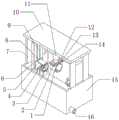
Fig. 1 is a schematic perspective view of a mechanical shaft cleaning device according to the present invention;
FIG. 2 is a schematic partial front cross-sectional structural view of a first annular support plate and a second annular support plate of a mechanical shaft cleaning apparatus according to the present invention;
FIG. 3 is a schematic side sectional view of a part of an arc-shaped support plate and an arc-shaped water distribution pipe of the mechanical shaft cleaning device according to the present invention;
FIG. 4 is a schematic top view of a part of a water tank of the mechanical shaft cleaning device according to the present invention;
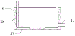
fig. 5 is a partial front sectional structural schematic view of a water storage tank body according to an embodiment 2 of the mechanical shaft cleaning device provided by the invention.
In the figure: 1 arc mounting panel, 2 first electric telescopic handle, 3 first annular supporting plates, 4 second annular supporting plates, 5 first supporting plates, 6 second supporting plates, 7 third supporting plates, 8 arc supporting plates, 9 first electric guide rails, 10 supporting top plates, 11 second electric telescopic handle, 12 first water guide hose, 13 annular distributive pipe, 14 fourth supporting plates, 15 water storage tank bodies, 16 drain pipes, 17 convex blocks, 18 first clamping plates, 19 third electric telescopic handles, 20 springs, 21 fourth electric telescopic handle, 22 second clamping plates, 23 second water guide hose, 24 arc distributive pipes, 25 sprinkler heads, 26 supersonic generator, 27 second electric guide rails.
Detailed Description
The technical solutions in the embodiments of the present invention will be clearly and completely described below with reference to the drawings in the embodiments of the present invention, and it is obvious that the described embodiments are only a part of the embodiments of the present invention, and not all of the embodiments.
In the description of the present invention, it is to be understood that the terms "upper", "lower", "front", "rear", "left", "right", "top", "bottom", "inner", "outer", and the like, indicate orientations or positional relationships based on the orientations or positional relationships shown in the drawings, are merely for convenience in describing the present invention and simplifying the description, and do not indicate or imply that the device or element being referred to must have a particular orientation, be constructed and operated in a particular orientation, and thus, should not be construed as limiting the present invention.
Example 1
Referring to fig. 1-4, a mechanical shaft cleaning device comprises a water storage tank body 15, wherein the inner walls of two sides of the bottom of the water storage tank body 15 are connected with second supporting plates 6 through bolts, the outer walls of the middle parts of two adjacent sides of the second supporting plates 6 are respectively provided with a first groove, the inner walls of the two first grooves are respectively connected with a first electric guide rail 9 which is vertically arranged through bolts, the outer walls of two adjacent sides of the first electric guide rails 9 are respectively connected with a first electric slider in a sliding way, the outer walls of two adjacent sides of the two first electric sliders are respectively connected with a first supporting plate 5 through bolts, the outer walls of the top and the bottom of two adjacent sides of the two first supporting plates 5 are respectively connected with an arc-shaped supporting plate 8 which is horizontally arranged through bolts, one side between the two arc-shaped supporting plates 8 which are positioned on the same side is connected with the same first annular supporting plate 3 through bolts, and the inner wall of second recess all has fourth electric telescopic handle 21 through bolted connection, the outer wall of fourth electric telescopic handle 21 one end all has second splint 22 through bolted connection, the middle part outer wall that lies in between two arc backup pads 8 with one side all has spring 20 through bolted connection, the outer wall of spring 20 one end all has second annular backup pad 4 through bolted connection, the third recess has all been seted up to 4 tops of second annular backup pad and bottom inner wall, and the inner wall of third recess all has third electric telescopic handle 19 through bolted connection, the outer wall of 19 one ends of third electric telescopic handle all has first splint 18 through bolted connection, and the impartial distance of the clamp mouthful inner wall of first splint 18 and second splint 22 is provided with lug 17.
In the invention, the outer walls of two sides of the top of the water storage tank body 15 are connected with two third supporting plates 7 through bolts, the outer walls of the tops of the four third supporting plates 7 are connected with the same supporting top plate 10 through bolts, the outer wall of the center of the bottom of the supporting top plate 10 is provided with a horizontally arranged fourth groove, the inner wall of the fourth groove is connected with a third electric guide rail through bolts, the outer wall of the bottom of the third electric guide rail is connected with a third electric slide block in a sliding manner, and the outer wall of the bottom of the third electric slide block is connected with a second electric telescopic rod 11 through bolts;
the outer wall of the bottom of the second electric telescopic rod 11 is connected with a fourth supporting plate 14 through a bolt, and the outer wall of the center of the bottom of the fourth supporting plate 14 is connected with two arc-shaped mounting plates 1 through hinges;
the outer walls of the two ends of the bottom of the fourth supporting plate 14 are connected with the first electric telescopic rods 2 through hinges, and the outer walls of the bottoms of the two first electric telescopic rods 2 are connected with the outer walls of the middle parts of the two arc-shaped mounting plates 1, which are far away from one end of each other, through hinges respectively;
the outer wall of the top of the fourth supporting plate 14 is connected with an annular water distribution pipe 13 through a bolt, the outer walls of two ends of the bottom of the annular water distribution pipe 13 are connected with second water guide hoses 23 through bolts, and the outer wall of one end of the top of the annular water distribution pipe 13 is connected with a first water guide hose 12 through a bolt;
the inner walls of the arc openings of the two arc-shaped mounting plates 1 are connected with arc-shaped water distribution pipes 24 through bolts, the inner walls of the arc openings of the two arc-shaped water distribution pipes 24 are connected with water spraying heads 25 which are arranged at equal intervals through bolts, and the outer walls of the bottoms of the two second water guide hoses 23 are connected with the outer walls of the tops of the two arc-shaped water distribution pipes 24 through bolts respectively;
the outer wall of one end of the bottom of the water storage tank body 15 is connected with an ultrasonic generator 26 through a bolt;
the outer walls of four corners of the bottom of the water storage box body 15 are respectively connected with a supporting pad through bolts, the outer wall of the bottom of one side of the water storage box body 15 is connected with a drain pipe 16 through bolts, and the inner wall of the circumference of the drain pipe 16 is connected with a drain valve through bolts.
The working principle is as follows: when in use, a user firstly needs to pass a mechanical shaft through the first annular supporting plate 3 and the second annular supporting plate 4, the third electric telescopic rod 19 and the fourth electric telescopic rod 21 respectively drive the first clamping plate 18 and the second clamping plate 22 to move, the first clamping plate 18 and the second clamping plate 22 clamp and fix the mechanical shaft, then the third electric sliding block and the second electric telescopic rod 11 adjust the position of the arc-shaped water distribution pipe 24, the first water guide hose 12 is connected with clear water, a water suction pump is externally connected to pump water into the first water guide hose 12, the water spray head 25 washes the circumference of the mechanical shaft, the wrapping type washing can effectively improve the comprehensive sufficiency of washing, after the preliminary washing is finished, the fourth electric telescopic rod 21 is contracted, the mechanical shaft is loosened by the second clamping plate 22, and the mechanical shaft is moved into the water storage box body 15 by the first electric sliding block, the mechanical shaft is cleaned by ultrasonic wave from the ultrasonic generator 26, and the cleaning sufficiency is further improved.
Example 2
Referring to fig. 1-5, a mechanical axis belt cleaning device still includes the mounting groove of seting up at the inner wall of water storage box 15 bottom both sides, and the inner wall of two mounting grooves all has second electronic guide rail 27 through bolted connection, and the equal sliding connection of top outer wall of two second electronic guide rail 27 has second electronic slider, and the bottom outer wall of two second backup pads 6 is respectively through bolted connection with the top outer wall of two second electronic sliders.
The working principle is as follows: when the device uses, start the electronic slider of second, drive two second backup pads 6 by the electronic slider of second and remove, and then can be convenient adjust the distance between two second backup pads 6, can realize carrying out the centre gripping to the mechanical axis of different length, improved the convenience that the device used.
The control mode of the invention is automatically controlled by the controller, the control circuit of the controller can be realized by simple programming of a person skilled in the art, the supply of the power supply also belongs to the common knowledge in the field, and the invention is mainly used for protecting mechanical devices, so the control mode and the circuit connection are not explained in detail in the invention.
The above description is only for the preferred embodiment of the present invention, but the scope of the present invention is not limited thereto, and any person skilled in the art should be considered to be within the technical scope of the present invention, and the technical solutions and the inventive concepts thereof according to the present invention should be equivalent or changed within the scope of the present invention.
Claims (9)
1. A mechanical shaft cleaning device comprises a water storage box body (15) and is characterized in that second supporting plates (6) are fixedly arranged on the inner walls of two sides of the bottom of the water storage box body (15), first grooves are formed in the outer walls of the middle parts of two adjacent sides of the second supporting plates (6), vertically arranged first electric guide rails (9) are fixedly arranged on the inner walls of the two first grooves, first electric sliders are connected to the outer walls of two adjacent sides of the first electric guide rails (9) in a sliding mode, first supporting plates (5) are fixedly arranged on the outer walls of two adjacent sides of the first electric sliders, horizontally arranged arc-shaped supporting plates (8) are fixedly arranged on the top and the outer walls of the bottom of two adjacent sides of the first supporting plates (5), and the same first annular supporting plate (3) is fixedly arranged on one side between the two arc-shaped supporting plates (8) on the same side, the inner walls of the top and the bottom of the first annular supporting plate (3) are both provided with second grooves, and the inner walls of the second grooves are fixedly provided with fourth electric telescopic rods (21), the outer walls of one ends of the fourth electric telescopic rods (21) are fixedly provided with second clamping plates (22), the outer walls of the middle parts between the two arc-shaped supporting plates (8) positioned at the same side are fixedly provided with springs (20), the outer walls of one ends of the springs (20) are fixedly provided with second annular supporting plates (4), the inner walls of the top and the bottom of the second annular supporting plate (4) are both provided with third grooves, and the inner walls of the third grooves are fixedly provided with third electric telescopic rods (19), the outer walls of one ends of the third electric telescopic rods (19) are fixedly provided with first clamping plates (18), and the inner walls of the clamping openings of the first clamping plate (18) and the second clamping plate (22) are provided with convex blocks (17) at equal distances.
2. The mechanical shaft cleaning device as claimed in claim 1, wherein two third support plates (7) are fixedly mounted on outer walls of two sides of the top of the water storage tank body (15), the same support top plate (10) is fixedly mounted on outer walls of the tops of the four third support plates (7), a horizontally arranged fourth groove is formed in an outer wall of the center of the bottom of the support top plate (10), a third electric guide rail is fixedly mounted on an inner wall of the fourth groove, a third electric slider is slidably connected to an outer wall of the bottom of the third electric guide rail, and a second electric telescopic rod (11) is fixedly mounted on an outer wall of the bottom of the third electric slider.
3. The mechanical shaft cleaning device as claimed in claim 2, characterized in that a fourth supporting plate (14) is fixedly mounted on the outer wall of the bottom of the second electric telescopic rod (11), and two arc-shaped mounting plates (1) are connected to the outer wall of the center of the bottom of the fourth supporting plate (14) through hinges.
4. The mechanical shaft cleaning device as claimed in claim 3, wherein the outer walls of the two ends of the bottom of the fourth supporting plate (14) are connected with the first electric telescopic rods (2) through hinges, and the outer walls of the bottoms of the two first electric telescopic rods (2) are respectively connected with the outer walls of the middle parts of the two arc-shaped mounting plates (1) at the ends far away from each other through hinges.
5. The mechanical shaft cleaning device as claimed in claim 3, wherein an annular water diversion pipe (13) is fixedly mounted on the outer wall of the top of the fourth supporting plate (14), second water guide hoses (23) are fixedly mounted on the outer walls of the two ends of the bottom of the annular water diversion pipe (13), and a first water guide hose (12) is fixedly mounted on the outer wall of one end of the top of the annular water diversion pipe (13).
6. The mechanical shaft cleaning device as claimed in claim 5, wherein the arc-shaped water distribution pipes (24) are fixedly mounted on the inner walls of the arc-shaped openings of the two arc-shaped mounting plates (1), the water spray heads (25) are equidistantly mounted on the inner walls of the arc-shaped openings of the two arc-shaped water distribution pipes (24), and the outer walls of the bottoms of the two second water guide hoses (23) are respectively connected with the outer walls of the tops of the two arc-shaped water distribution pipes (24) through bolts.
7. The mechanical shaft cleaning device as claimed in claim 1, wherein an ultrasonic generator (26) is fixedly mounted on the outer wall of one end of the bottom of the water storage tank body (15).
8. The mechanical shaft cleaning device as claimed in claim 1, wherein the outer walls of four corners of the bottom of the water storage tank body (15) are fixedly provided with supporting pads, the outer wall of the bottom of one side of the water storage tank body (15) is fixedly provided with a drain pipe (16), and the inner wall of the circumference of the drain pipe (16) is fixedly provided with a drain valve.
9. The mechanical shaft cleaning device as claimed in claim 1, wherein mounting grooves are formed in inner walls of two sides of the bottom of the water storage tank body (15), second electric guide rails (27) are fixedly mounted on the inner walls of the two mounting grooves, second electric sliders are slidably connected to outer walls of tops of the two second electric guide rails (27), and outer walls of bottoms of the two second support plates (6) are connected to outer walls of tops of the two second electric sliders through bolts.
Priority Applications (1)
| Application Number | Priority Date | Filing Date | Title |
|---|---|---|---|
| CN202010734118.2A CN111842300A (en) | 2020-07-28 | 2020-07-28 | Mechanical shaft cleaning device |
Applications Claiming Priority (1)
| Application Number | Priority Date | Filing Date | Title |
|---|---|---|---|
| CN202010734118.2A CN111842300A (en) | 2020-07-28 | 2020-07-28 | Mechanical shaft cleaning device |
Publications (1)
| Publication Number | Publication Date |
|---|---|
| CN111842300A true CN111842300A (en) | 2020-10-30 |
Family
ID=72947385
Family Applications (1)
| Application Number | Title | Priority Date | Filing Date |
|---|---|---|---|
| CN202010734118.2A Withdrawn CN111842300A (en) | 2020-07-28 | 2020-07-28 | Mechanical shaft cleaning device |
Country Status (1)
| Country | Link |
|---|---|
| CN (1) | CN111842300A (en) |
Cited By (1)
| Publication number | Priority date | Publication date | Assignee | Title |
|---|---|---|---|---|
| CN112547610A (en) * | 2020-11-24 | 2021-03-26 | 常熟市恒丰轧辊有限公司 | Water washing device for production of cold roll |
-
2020
- 2020-07-28 CN CN202010734118.2A patent/CN111842300A/en not_active Withdrawn
Cited By (2)
| Publication number | Priority date | Publication date | Assignee | Title |
|---|---|---|---|---|
| CN112547610A (en) * | 2020-11-24 | 2021-03-26 | 常熟市恒丰轧辊有限公司 | Water washing device for production of cold roll |
| CN112547610B (en) * | 2020-11-24 | 2022-07-26 | 常熟市恒丰轧辊有限公司 | Water washing device for production of cold roll |
Similar Documents
| Publication | Publication Date | Title |
|---|---|---|
| CN111002146A (en) | Metal nozzle stub lateral wall deburring device that polishes | |
| CN210173270U (en) | Burnishing device is used in hardware fitting processing | |
| CN106623175A (en) | Automatic cleaning and drying all-in-one machine for CNC fixtures | |
| CN111842300A (en) | Mechanical shaft cleaning device | |
| CN111842364A (en) | Angle-adjustable pipeline inner wall cleaning device for machining | |
| CN212633709U (en) | Angle-adjustable pipeline inner wall cleaning device for machining | |
| CN214235251U (en) | Part machining's belt cleaning device for mechanical equipment | |
| CN212856832U (en) | Mould belt cleaning device is used in mould production | |
| CN215588730U (en) | Plastic mold's burnishing and polishing equipment of weathering | |
| CN212044152U (en) | Welding seam burnishing device for welding pipe making machine line | |
| CN109986436B (en) | Automatic workpiece processing equipment | |
| CN113414662A (en) | Burr removing device with raise dust suppression structure for hardware fitting machining | |
| CN218619063U (en) | Weld clean fixed station | |
| CN213164734U (en) | Energy-saving efficient rust removal device | |
| CN220425695U (en) | Hardware paint spraying device with adjustable angle | |
| CN216631778U (en) | Multi-angle adjustable spraying flushing equipment for punch machining | |
| CN112387502A (en) | Columnar workpiece paint spraying device for machining | |
| CN213614394U (en) | High-efficient CNC processing milling machine with wash structure | |
| CN216731001U (en) | Quick deburring device for valve plate welding alignment groove | |
| CN117463684B (en) | Oxygen-free copper cleaning and processing equipment and method capable of continuously feeding | |
| CN219925391U (en) | Water cooling device for machine tool machining | |
| CN215096468U (en) | 5G network router production is with spouting yard device | |
| CN213223599U (en) | Aluminum product ultrasonic cleaner | |
| CN216330311U (en) | Effectual punch press of high efficiency shock attenuation | |
| CN220760254U (en) | Auto-parts mold processing belt cleaning device |
Legal Events
| Date | Code | Title | Description |
|---|---|---|---|
| PB01 | Publication | ||
| PB01 | Publication | ||
| SE01 | Entry into force of request for substantive examination | ||
| SE01 | Entry into force of request for substantive examination | ||
| WW01 | Invention patent application withdrawn after publication |
Application publication date: 20201030 |
|
| WW01 | Invention patent application withdrawn after publication |