CN111828362A - vacuum pump system - Google Patents
vacuum pump system Download PDFInfo
- Publication number
- CN111828362A CN111828362A CN202010141869.3A CN202010141869A CN111828362A CN 111828362 A CN111828362 A CN 111828362A CN 202010141869 A CN202010141869 A CN 202010141869A CN 111828362 A CN111828362 A CN 111828362A
- Authority
- CN
- China
- Prior art keywords
- pressure
- pump
- gas
- pressure detection
- detection unit
- Prior art date
- Legal status (The legal status is an assumption and is not a legal conclusion. Google has not performed a legal analysis and makes no representation as to the accuracy of the status listed.)
- Granted
Links
Images


Classifications
-
- F—MECHANICAL ENGINEERING; LIGHTING; HEATING; WEAPONS; BLASTING
- F04—POSITIVE - DISPLACEMENT MACHINES FOR LIQUIDS; PUMPS FOR LIQUIDS OR ELASTIC FLUIDS
- F04D—NON-POSITIVE-DISPLACEMENT PUMPS
- F04D27/00—Control, e.g. regulation, of pumps, pumping installations or pumping systems specially adapted for elastic fluids
- F04D27/001—Testing thereof; Determination or simulation of flow characteristics; Stall or surge detection, e.g. condition monitoring
-
- C—CHEMISTRY; METALLURGY
- C23—COATING METALLIC MATERIAL; COATING MATERIAL WITH METALLIC MATERIAL; CHEMICAL SURFACE TREATMENT; DIFFUSION TREATMENT OF METALLIC MATERIAL; COATING BY VACUUM EVAPORATION, BY SPUTTERING, BY ION IMPLANTATION OR BY CHEMICAL VAPOUR DEPOSITION, IN GENERAL; INHIBITING CORROSION OF METALLIC MATERIAL OR INCRUSTATION IN GENERAL
- C23C—COATING METALLIC MATERIAL; COATING MATERIAL WITH METALLIC MATERIAL; SURFACE TREATMENT OF METALLIC MATERIAL BY DIFFUSION INTO THE SURFACE, BY CHEMICAL CONVERSION OR SUBSTITUTION; COATING BY VACUUM EVAPORATION, BY SPUTTERING, BY ION IMPLANTATION OR BY CHEMICAL VAPOUR DEPOSITION, IN GENERAL
- C23C14/00—Coating by vacuum evaporation, by sputtering or by ion implantation of the coating forming material
- C23C14/0021—Reactive sputtering or evaporation
- C23C14/0036—Reactive sputtering
- C23C14/0042—Controlling partial pressure or flow rate of reactive or inert gases with feedback of measurements
-
- C—CHEMISTRY; METALLURGY
- C23—COATING METALLIC MATERIAL; COATING MATERIAL WITH METALLIC MATERIAL; CHEMICAL SURFACE TREATMENT; DIFFUSION TREATMENT OF METALLIC MATERIAL; COATING BY VACUUM EVAPORATION, BY SPUTTERING, BY ION IMPLANTATION OR BY CHEMICAL VAPOUR DEPOSITION, IN GENERAL; INHIBITING CORROSION OF METALLIC MATERIAL OR INCRUSTATION IN GENERAL
- C23C—COATING METALLIC MATERIAL; COATING MATERIAL WITH METALLIC MATERIAL; SURFACE TREATMENT OF METALLIC MATERIAL BY DIFFUSION INTO THE SURFACE, BY CHEMICAL CONVERSION OR SUBSTITUTION; COATING BY VACUUM EVAPORATION, BY SPUTTERING, BY ION IMPLANTATION OR BY CHEMICAL VAPOUR DEPOSITION, IN GENERAL
- C23C14/00—Coating by vacuum evaporation, by sputtering or by ion implantation of the coating forming material
- C23C14/22—Coating by vacuum evaporation, by sputtering or by ion implantation of the coating forming material characterised by the process of coating
- C23C14/56—Apparatus specially adapted for continuous coating; Arrangements for maintaining the vacuum, e.g. vacuum locks
-
- C—CHEMISTRY; METALLURGY
- C23—COATING METALLIC MATERIAL; COATING MATERIAL WITH METALLIC MATERIAL; CHEMICAL SURFACE TREATMENT; DIFFUSION TREATMENT OF METALLIC MATERIAL; COATING BY VACUUM EVAPORATION, BY SPUTTERING, BY ION IMPLANTATION OR BY CHEMICAL VAPOUR DEPOSITION, IN GENERAL; INHIBITING CORROSION OF METALLIC MATERIAL OR INCRUSTATION IN GENERAL
- C23C—COATING METALLIC MATERIAL; COATING MATERIAL WITH METALLIC MATERIAL; SURFACE TREATMENT OF METALLIC MATERIAL BY DIFFUSION INTO THE SURFACE, BY CHEMICAL CONVERSION OR SUBSTITUTION; COATING BY VACUUM EVAPORATION, BY SPUTTERING, BY ION IMPLANTATION OR BY CHEMICAL VAPOUR DEPOSITION, IN GENERAL
- C23C16/00—Chemical coating by decomposition of gaseous compounds, without leaving reaction products of surface material in the coating, i.e. chemical vapour deposition [CVD] processes
-
- F—MECHANICAL ENGINEERING; LIGHTING; HEATING; WEAPONS; BLASTING
- F04—POSITIVE - DISPLACEMENT MACHINES FOR LIQUIDS; PUMPS FOR LIQUIDS OR ELASTIC FLUIDS
- F04D—NON-POSITIVE-DISPLACEMENT PUMPS
- F04D15/00—Control, e.g. regulation, of pumps, pumping installations or systems
-
- F—MECHANICAL ENGINEERING; LIGHTING; HEATING; WEAPONS; BLASTING
- F04—POSITIVE - DISPLACEMENT MACHINES FOR LIQUIDS; PUMPS FOR LIQUIDS OR ELASTIC FLUIDS
- F04D—NON-POSITIVE-DISPLACEMENT PUMPS
- F04D19/00—Axial-flow pumps
- F04D19/02—Multi-stage pumps
- F04D19/04—Multi-stage pumps specially adapted to the production of a high vacuum, e.g. molecular pumps
- F04D19/042—Turbomolecular vacuum pumps
-
- F—MECHANICAL ENGINEERING; LIGHTING; HEATING; WEAPONS; BLASTING
- F04—POSITIVE - DISPLACEMENT MACHINES FOR LIQUIDS; PUMPS FOR LIQUIDS OR ELASTIC FLUIDS
- F04D—NON-POSITIVE-DISPLACEMENT PUMPS
- F04D19/00—Axial-flow pumps
- F04D19/02—Multi-stage pumps
- F04D19/04—Multi-stage pumps specially adapted to the production of a high vacuum, e.g. molecular pumps
- F04D19/044—Holweck-type pumps
-
- F—MECHANICAL ENGINEERING; LIGHTING; HEATING; WEAPONS; BLASTING
- F04—POSITIVE - DISPLACEMENT MACHINES FOR LIQUIDS; PUMPS FOR LIQUIDS OR ELASTIC FLUIDS
- F04D—NON-POSITIVE-DISPLACEMENT PUMPS
- F04D27/00—Control, e.g. regulation, of pumps, pumping installations or pumping systems specially adapted for elastic fluids
- F04D27/008—Stop safety or alarm devices, e.g. stop-and-go control; Disposition of check-valves
-
- F—MECHANICAL ENGINEERING; LIGHTING; HEATING; WEAPONS; BLASTING
- F04—POSITIVE - DISPLACEMENT MACHINES FOR LIQUIDS; PUMPS FOR LIQUIDS OR ELASTIC FLUIDS
- F04D—NON-POSITIVE-DISPLACEMENT PUMPS
- F04D29/00—Details, component parts, or accessories
- F04D29/40—Casings; Connections of working fluid
- F04D29/42—Casings; Connections of working fluid for radial or helico-centrifugal pumps
- F04D29/4206—Casings; Connections of working fluid for radial or helico-centrifugal pumps especially adapted for elastic fluid pumps
- F04D29/4213—Casings; Connections of working fluid for radial or helico-centrifugal pumps especially adapted for elastic fluid pumps suction ports
-
- F—MECHANICAL ENGINEERING; LIGHTING; HEATING; WEAPONS; BLASTING
- F05—INDEXING SCHEMES RELATING TO ENGINES OR PUMPS IN VARIOUS SUBCLASSES OF CLASSES F01-F04
- F05D—INDEXING SCHEME FOR ASPECTS RELATING TO NON-POSITIVE-DISPLACEMENT MACHINES OR ENGINES, GAS-TURBINES OR JET-PROPULSION PLANTS
- F05D2260/00—Function
- F05D2260/60—Fluid transfer
- F05D2260/607—Preventing clogging or obstruction of flow paths by dirt, dust, or foreign particles
Landscapes
- Engineering & Computer Science (AREA)
- Mechanical Engineering (AREA)
- Chemical & Material Sciences (AREA)
- General Engineering & Computer Science (AREA)
- Materials Engineering (AREA)
- Chemical Kinetics & Catalysis (AREA)
- Metallurgy (AREA)
- Organic Chemistry (AREA)
- General Chemical & Material Sciences (AREA)
- Physics & Mathematics (AREA)
- Fluid Mechanics (AREA)
- Non-Positive Displacement Air Blowers (AREA)
- Control Of Positive-Displacement Air Blowers (AREA)
Abstract
本发明的课题在于准确度良好地推断堆积物的堆积状态。真空泵包括:真空计(110),检测自吸气口吸入的气体向排气口(65)流动的气体流路的气体压力;以及推断部(24),基于由真空计(110)检测到的气体压力,推断堆积于气体流路中的堆积物的状态。
The subject of this invention is to estimate the accumulation state of a deposit with high accuracy. The vacuum pump includes: a vacuum gauge (110) for detecting the gas pressure of a gas flow path through which gas sucked from the suction port flows to the exhaust port (65); The gas pressure is used to estimate the state of the deposits accumulated in the gas flow path.
Description
技术领域technical field
本发明涉及一种真空泵系统。The present invention relates to a vacuum pump system.
背景技术Background technique
在半导体或液晶面板的制造中的干式蚀刻或化学气相沉积(Chemical VaporDeposition,CVD)等工序中,在高真空的工艺腔室(process chamber)内进行处理,因此例如利用涡轮分子泵之类的真空泵对工艺腔室内的气体进行排气来维持高真空。当对干式蚀刻或CVD等的工艺腔室内的气体进行排气时,伴随气体的排出,反应产物堆积于泵内。In processes such as dry etching or chemical vapor deposition (CVD) in the manufacture of semiconductor or liquid crystal panels, processing is performed in a high-vacuum process chamber, so for example, a turbomolecular pump is used. A vacuum pump maintains a high vacuum by evacuating the gas in the process chamber. When the gas in a process chamber such as dry etching or CVD is exhausted, reaction products are deposited in the pump along with the exhaust of the gas.
关于此种反应产物的堆积,在专利文献1中公开了一种探测泵内所堆积的产物的方法。在专利文献1中公开的堆积物探测方法中,测量对泵的旋转体进行旋转驱动的马达的电流值,在测量值相对于马达电流初始值的变化量为规定值以上的情况下发出警告。Regarding the accumulation of such a reaction product,
现有技术文献prior art literature
专利文献Patent Literature
专利文献1:日本专利第5767632号公报Patent Document 1: Japanese Patent No. 5767632
发明内容SUMMARY OF THE INVENTION
发明所要解决的问题The problem to be solved by the invention
然而,实际上,即便在单一的工艺内,被排气的气体流量也大幅度变动,因此伴随气体流量的变动,对旋转体进行旋转驱动的马达的电流值也大幅度变动。因此,无法避免错误判定。However, in practice, even in a single process, the flow rate of the gas to be exhausted varies greatly, and accordingly, the current value of the motor for rotationally driving the rotary body also varies greatly with the variation in the gas flow rate. Therefore, erroneous determination cannot be avoided.
解决问题的技术手段technical solutions to problems
本发明所提供的真空泵系统包括:真空泵,具有吸气口、排气口、及压力检测部,所述压力检测部检测自吸气口吸入的气体向排气口流动的气体流路的气体压力;以及计算装置,基于由所述压力检测部检测到的所述气体压力,计算堆积于所述气体流路中的堆积物的状态。The vacuum pump system provided by the present invention includes: a vacuum pump, which has a suction port, an exhaust port, and a pressure detection part, and the pressure detection part detects the gas pressure of the gas flow path in which the gas sucked from the suction port flows to the exhaust port and calculating means for calculating the state of the deposit accumulated in the gas flow path based on the gas pressure detected by the pressure detection unit.
发明的效果effect of invention
根据本发明,可准确度良好地推断堆积于排气流路中的堆积物的堆积状态。According to the present invention, the deposition state of the deposits deposited in the exhaust flow path can be estimated with high accuracy.
附图说明Description of drawings
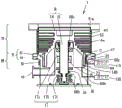
图1是表示第一实施方式的涡轮分子泵的构成的图。FIG. 1 is a diagram showing a configuration of a turbomolecular pump according to a first embodiment.
图2是表示第一实施方式的涡轮分子泵中使用的堆积物推断装置的构成的图。2 is a diagram showing a configuration of a deposit estimation device used in the turbomolecular pump of the first embodiment.
图3是表示第二实施方式的涡轮分子泵的构成的图。3 is a diagram showing a configuration of a turbomolecular pump according to a second embodiment.
图4是表示第三实施方式的涡轮分子泵的构成的图。4 is a diagram showing a configuration of a turbomolecular pump according to a third embodiment.
图5是表示第四实施方式的涡轮分子泵的构成的图。FIG. 5 is a diagram showing a configuration of a turbomolecular pump according to a fourth embodiment.
图6是表示第五实施方式的涡轮分子泵的构成的图。FIG. 6 is a diagram showing a configuration of a turbomolecular pump according to a fifth embodiment.
图7是表示变形例5的真空泵系统的构成的图。FIG. 7 is a diagram showing the configuration of a vacuum pump system of Modification 5. FIG.
符号的说明Explanation of symbols
1、1A:涡轮分子泵1. 1A: Turbo molecular pump
1B:真空泵系统1B: Vacuum pump system
2:底座2: base
3:泵转子3: Pump rotor
4:马达4: Motor
12:控制器12: Controller
20:固定叶片20: Fixed blades
21a:定子圆筒部21a: Stator cylindrical part
24:堆积物推断部24: Deposit Estimation Department
30:旋转叶片30: Rotary blades
31a:转子圆筒部31a: Rotor cylinder part
60:底座60: Base
61:罩体61: cover body
71~74:气体流路71 to 74: Gas flow path
80、95:调压阀80, 95: pressure regulating valve
110、120、130、140、150:真空计110, 120, 130, 140, 150: Vacuum gauge
200:外部服务器200: External server
201:通信I/F201: Communication I/F
202:堆积物推断部202: Deposit Estimation Department
203:存储部203: Storage Department
400:通信I/F400: Communication I/F
具体实施方式Detailed ways
以下,参照图对具体实施方式进行说明。Hereinafter, specific embodiments will be described with reference to the drawings.
-第一实施方式--First Embodiment-
图1是表示第一实施方式的真空泵1的图,图2是表示对真空泵1进行驱动控制的控制器12的图。真空泵1经由未图示的调压阀安装于未图示的工艺腔室。所述真空泵1及调压阀等被控制器12(参照图2)驱动控制,以对工艺腔室内的气压进行调压控制。即,控制器12进行调压阀的控制、泵马达的控制、温度控制、磁悬浮控制。控制器12还进行堆积物推断计算。堆积物推断计算基于真空泵1的气体流路的气体压力,推断堆积于流路内的堆积物的堆积状态。FIG. 1 is a diagram showing the
之后将参照图2来叙述控制器12。The
图1所示的真空泵1是包括涡轮泵部TP以及霍尔维克(Holweck)泵部HP作为排气功能部的磁轴承式的涡轮分子泵,所述涡轮泵部TP包括涡轮叶片,所述霍尔维克泵部HP包括螺旋型的槽。涡轮泵部TP与霍尔维克泵部HP设置于被称为壳体(housing)的泵框体11内。泵框体11具有底座60、以及层叠于底座60上的罩体(casing)61。在底座60的侧面设置有排气口65,在罩体61的上表面设置有吸气口61a。吸气口61a经由未图示的调压阀而与作为真空室的工艺腔室连接,排气口65与未图示的被称为前级泵(back pump)的辅助泵连接。有时也设置调压阀来代替辅助泵。利用涡轮分子泵1对工艺腔室内进行真空排气,利用调压阀调压至规定的压力。The
本发明不限于在排气功能部中包括涡轮泵部TP及霍尔维克泵部HP的真空泵,也可适用于仅包括涡轮叶片的真空泵、仅包括西格班泵(Siegbahn pump)或霍尔维克泵等牵引泵(drag pump)的真空泵、或将所述泵组合而成的真空泵。The present invention is not limited to a vacuum pump including a turbo pump part TP and a Hallwick pump part HP in the exhaust function part, but can also be applied to a vacuum pump including only a turbine vane, a Siegbahn pump or a Hall only A vacuum pump of a drag pump such as a Vic pump, or a vacuum pump formed by combining the above-mentioned pumps.
此外,霍尔维克泵部HP也称为螺纹槽泵部。In addition, the Hallwick pump section HP is also referred to as a thread groove pump section.
在泵框体11中设置有旋转体R。旋转体R包括泵转子14、以及紧固于泵转子14的转子轴15。转子轴15由泵马达16旋转驱动。A rotary body R is provided in the
在泵转子14中,在上游侧形成有多段旋转叶片14a,在下游侧形成有构成螺纹槽泵的圆筒部14b。对应于所述旋转叶片14a与圆筒部14b,在固定侧设置有多个固定叶片定子62、及圆筒状的螺杆定子64。有在螺杆定子64的内周面形成螺纹槽的形式、及在圆筒部14b的外周面形成螺纹槽的形式等。各固定叶片定子62经由间隔圈(spacer ring)63载置于底座60上。In the
泵框体11的上游侧为涡轮泵部TP,下游侧为霍尔维克泵部HP。The upstream side of the
转子轴15由设置于底座60的径向磁轴承17A、径向磁轴承17B与轴向磁轴承17C予以磁悬浮支撑,并由马达16旋转驱动。各磁轴承17A~磁轴承17C包括电磁铁与位移传感器,通过位移传感器来检测转子轴15的悬浮位置。转子轴15的转速通过转速传感器18来检测。在磁轴承17A~磁轴承17C不工作的情况下,转子轴15由紧急用机械轴承66a、机械轴承66b来支撑。将磁轴承17A~磁轴承17C以代表符号17来示出。The
当通过马达16来使紧固有泵转子14的转子轴15高速旋转时,吸气口61a侧的气体分子被朝排气口65侧排气。When the
在底座60中设置有加热器19、及供冷却水等冷媒流动的冷媒配管20。冷媒配管20与未图示的冷媒供给配管连接,可通过设置于冷媒供给配管的电磁开关阀的开关控制来调整朝冷媒配管20的冷媒流量。当对反应产物容易堆积的气体进行排气时,为了抑制朝螺纹槽泵部分或下游侧的旋转叶片14a的产物堆积,通过打开/关闭加热器19、及打开/关闭在冷媒配管20中流动的冷媒的流量,而以例如螺杆定子固定部附近的底座温度变成规定温度的方式进行温度调整。The
(控制器12)(controller 12)
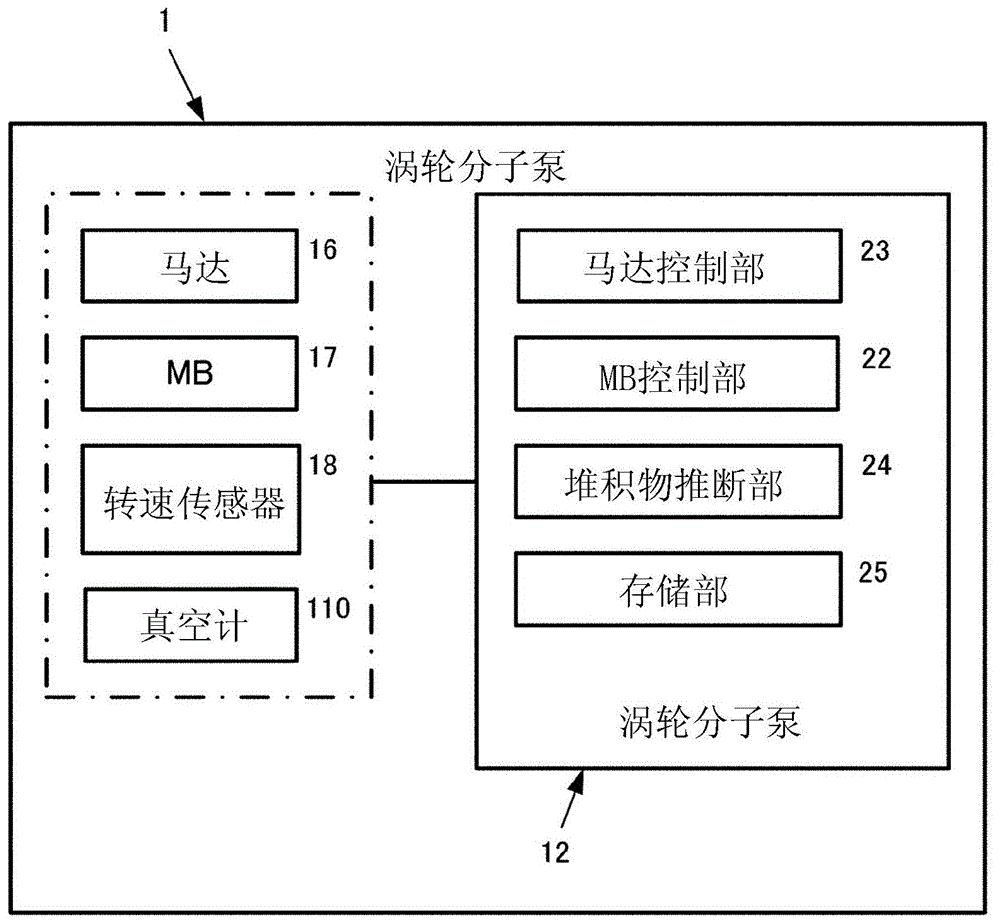
参照图2对控制器12进行说明。The
如图1所示,涡轮分子泵1包括马达16、磁轴承(MB)17及转速传感器18。控制器12包括中央处理器(central processing unit,CPU)、现场可编程门阵列(field programmablegate array,FPGA)等计算处理装置。计算处理装置作为马达控制部23、磁轴承控制部(MB控制部)22、堆积物推断部24发挥功能。在存储部25中保存有用以对泵进行驱动控制的程序、及用以推断堆积物的堆积状态的程序(以下称为堆积物推断程序)等。如后所述,在存储部25中预先制作并存储有表示相对于气体压力的堆积物的堆积状态的表。As shown in FIG. 1 , the
马达控制部23基于由转速传感器18检测到的旋转信号来推断转子轴15的转速,并基于经推断的转速来将马达16控制成规定目标转速。若气体流量变大,则对于泵转子14的负荷增加,因此马达16的转速下降。马达控制部23以由转速传感器18检测到的转速与规定目标转速的差变成零的方式控制马达电流,由此维持规定目标转速(额定转速)。The
磁轴承17包括轴承电磁铁、及用以检测转子轴15的悬浮位置的位移传感器。The
如后所述,真空计110是检测涡轮泵部TP与霍尔维克泵部HP之间的边界区域内的气体流路71的气体压力的压力计。As will be described later, the
堆积物推断部24是如下的计算装置:通过执行保存于存储部25中的堆积物推断程序,基于由真空计110检测的气体压力P110,推断堆积于涡轮分子泵1的气体流路中的堆积物的堆积状态。将因堆积物的过剩堆积而涡轮分子泵1无法正常运转的状态定义成泵异常状态。而且,为了将所述泵异常状态防患于未然,在与产生泵异常状态的时间点相比具有足够的富余时间之前的时间点,预测泵异常产生。其中,此处将已预测到泵异常的时间点称为泵异常检测。The
此外,一般而言涡轮分子泵1以一定转速连续旋转,根据工艺腔室的目标压力来控制调压阀的开度。调压阀的开度控制有由控制器12进行、或者由另设的主控制器进行等各种形式。In addition, in general, the
(堆积物状态的检测)(Detection of accumulation state)
如上所述,在第一实施方式的涡轮分子泵1中设置有真空计110,所述真空计110检测涡轮泵部TP与霍尔维克泵部HP之间的边界区域、即自涡轮泵部TP连通至霍尔维克泵部HP的流路71的气体压力。即,在底座60的外周面设置有气体压力测量端口60a,在所述气体压力测量端口60a与所述边界区域内的流路71之间设置有气体压力测量用通路(以下称为测量用通路)67。As described above, the
基于真空计110的检测压力P110,通过安装于控制器12的存储部25中的堆积物推断程序来推断堆积物的堆积量、或者预测堆积量。在第一实施方式中,例如可以如下方式推断堆积物的堆积量。Based on the detected pressure P110 of the
在控制器12的存储部25中,预先制作并存储有表示相对于气体压力的堆积物的堆积状态的表(以下称为气体压力-堆积状态表)。以检测到的气体压力P110参照气体压力-堆积状态表来读取堆积物的堆积状态。在表示堆积状态的气体压力为规定的阈值以上的情况下,警告涡轮分子泵1的运转不正常、即异常。所述情况下的阈值为异常判定阈值。In the
此外,有时即便气体压力P110为小于异常判定阈值的值,但在不久的将来例如1小时后也会成为异常判定阈值以上。也可将此种气体压力设定为异常判定阈值。即,可设定多个异常判定阈值并告知用户以进行警告。In addition, even if the gas pressure P110 is a value smaller than the abnormality determination threshold value, it may become the abnormality determination threshold value or more in the near future, for example, one hour later. Such gas pressure may also be set as an abnormality determination threshold value. That is, a plurality of abnormality determination thresholds can be set and notified to the user for warning.
如以上所说明,在第一实施方式的真空泵中具有以下作用效果。As described above, the vacuum pump of the first embodiment has the following functions and effects.
因伴随堆积物的增加的气体压力的变动比马达电流的变动大,因此可尽早检测出堆积物的状态变化。由于是通过马达电流的变动来判定堆积物增加,因此例如若压力不上升至150Pa左右,则无法准确度良好地进行检测。关于所述方面,在通过涡轮泵部TP与霍尔维克泵部HP之间的边界区域内的流路71的压力变动来检测堆积物的堆积状态的实施方式中,只要为例如20Pa~50Pa左右的范围,便可利用真空计110准确地进行检测。另外,在压力以20Pa~50Pa左右变动时,马达电流在0.1A~0.5A的范围内变动,但若考虑到叠加于马达电流上的噪声等,则难以进行高准确度的检测。Since the fluctuation of the gas pressure accompanying the increase of the deposit is larger than the fluctuation of the motor current, the state change of the deposit can be detected early. Since the increase of the deposit is determined by the fluctuation of the motor current, it cannot be detected with high accuracy unless the pressure rises to about 150 Pa, for example. With regard to the above-mentioned aspect, in the embodiment in which the deposition state of the deposits is detected by the pressure fluctuation of the
-第二实施方式--Second Embodiment-
第二实施方式的涡轮分子泵1是如下的真空泵:不仅可检测在涡轮泵部TP与霍尔维克泵部HP之间的边界区域内的流路71中流动的气体压力,还可检测涡轮泵部TP的入口侧气体压力来监视堆积物的堆积状态。The
以下,参照图3主要对与第一实施方式不同的部位进行说明。Hereinafter, parts different from those of the first embodiment will be mainly described with reference to FIG. 3 .
在第二实施方式的涡轮分子泵1中设置有真空计120,所述真空计120测量涡轮泵部TP的入口侧气体压力。吸气口61a具有供来自工艺腔室的排出气体经由未图示的调压阀而流入的流路72,真空计120检测所述流路72的气体压力。即,在罩体61的外表面设置有气体压力测量端口61b,在所述气体压力测量端口61b与所述入口侧气体流路72之间设置有气体压力测量用通路(以下称为测量用通路)61c。图3示意性地说明真空计120的安装位置,气体压力测量端口61b的设置位置可根据涡轮分子泵1的规格来适当地设定。The
基于真空计110的检测压力P110与真空计120的检测压力P120,通过安装于控制器12的存储部25中的堆积物推断程序来推断堆积物的堆积量、或者预测堆积量。在第二实施方式中,例如可以如下方式推断堆积物的堆积量。Based on the detection pressure P110 of the
在第二实施方式的真空泵中,分别利用真空计110与真空计120来检测涡轮泵部TP与霍尔维克泵部HP之间的边界区域内的流路71的气体压力P110、及吸气口61a的气体压力P120。气体压力P110与气体压力P120的差压ΔP1表示涡轮泵部TP的自气体流入口至气体流出口之间的气体流路的压力损失。因此,测量涡轮分子泵1刚开始使用后的差压ΔP1并作为基准值加以存储,从而可根据自所述差压ΔP1的偏离来检测堆积物的堆积状态。In the vacuum pump of the second embodiment, the
在控制器12的存储部25中,预先制作并存储有表示相对于差压ΔP1的堆积物的堆积状态的表。以检测到的气体压力P110与气体压力P120的差压ΔP1来参照表并读出堆积物的堆积状态。在差压ΔP1为规定的阈值以上的情况下,警告涡轮分子泵1的运转不正常、即异常。所述情况下的阈值为异常判定阈值。In the
此外,有时即便气体压力的差压ΔP1为小于异常判定阈值的值,在不久的将来例如1小时后也会成为异常判定阈值以上。也可将此种气体压力设定为异常判定阈值。即,可设定多个异常判定阈值并告知用户以进行警告。In addition, even if the differential pressure ΔP1 of the gas pressure is a value smaller than the abnormality determination threshold value, it may become equal to or more than the abnormality determination threshold value in the near future, for example, one hour later. Such gas pressure may also be set as an abnormality determination threshold value. That is, a plurality of abnormality determination thresholds can be set and notified to the user for warning.
如以上所说明,在第二实施方式的真空泵中具有以下作用效果。As described above, the vacuum pump of the second embodiment has the following effects.
在仅利用涡轮泵部TP的出口压力的变动来检测堆积物的堆积状态的第一实施方式中,当在工艺腔室内设定多个目标压力时,无法准确地检测堆积状态。关于所述方面,在第二实施方式中,由于使用压力P110与压力P120的差压ΔP1,因此即便在涡轮分子泵1的吸气口61a的压力不同的情况下,也可准确地检测涡轮泵部TP内的压力损失。其结果,即便压力目标值根据工艺腔室内的处理内容而不同,即,无关于工艺腔室中进行的处理的工艺配方(recipe),可进行高准确度的堆积物检测。In the first embodiment in which the deposition state of the deposits is detected only by the fluctuation of the outlet pressure of the turbo pump portion TP, when a plurality of target pressures are set in the process chamber, the deposition state cannot be accurately detected. In this regard, in the second embodiment, since the differential pressure ΔP1 between the pressure P110 and the pressure P120 is used, even when the pressure of the
-第三实施方式--Third Embodiment-
第三实施方式的涡轮分子泵1是如下的真空泵:不仅可检测在涡轮泵部TP与霍尔维克泵部HP之间的边界区域内的流路71中流动的气体压力,还可检测霍尔维克泵部HP的出口侧气体压力来监视堆积物的堆积状态。The
以下,参照图4主要对与第一实施方式不同的部位进行说明。Hereinafter, with reference to FIG. 4, the part different from 1st Embodiment is mainly demonstrated.
在第三实施方式的涡轮分子泵1中设置有真空计130,所述真空计130测量霍尔维克泵部HP的出口侧气体压力。在底座60的外表面设置有气体压力测量端口60b,在所述气体压力测量端口60b与霍尔维克泵部HP的出口侧气体流路73之间设置有气体压力测量用通路(以下称为测量用通路)68。图4示意性地说明真空计130的安装位置,气体压力测量端口60b的设置位置可根据涡轮分子泵1的规格来适当地设定。The
基于真空计110的检测压力P110与真空计130的检测压力P130,通过安装于控制器12的存储部25中的堆积物推断程序来推断堆积物的堆积量、或者预测堆积量。在第三实施方式中,例如可以如下方式推断堆积物的堆积量。Based on the detection pressure P110 of the
在第三实施方式的真空泵中,分别利用真空计110与真空计130来检测涡轮泵部TP与霍尔维克泵部HP之间的边界区域内的流路71的气体压力P110、及霍尔维克泵部HP的出口侧附近的流路73的气体压力P130。气体压力P110与气体压力P130的差压ΔP2表示霍尔维克泵部HP的自气体流入口至气体流出口之间的气体流路的压力损失。因此,测量涡轮分子泵1刚开始使用后的差压ΔP2并作为基准值加以存储,从而可根据自所述差压ΔP2的偏离来检测堆积物的堆积状态。In the vacuum pump of the third embodiment, the
在控制器12的存储部25中,预先制作并存储有表示相对于差压ΔP2的堆积物的堆积状态的表。以检测到的气体压力P110与气体压力P130的差压ΔP2来参照表并读出堆积物的堆积状态。在堆积状态为规定的阈值以上的情况下,警告涡轮分子泵1的运转不正常、即异常。所述情况下的阈值为异常判定阈值。In the
此外,有时即便气体压力的差压ΔP2为小于异常判定阈值的值,在不久的将来例如1小时后也会成为异常判定阈值以上。也可将此种气体压力设定为异常判定阈值。即,可设定多个异常判定阈值并告知用户以进行警告。In addition, even if the differential pressure ΔP2 of the gas pressure is a value smaller than the abnormality determination threshold value, it may become equal to or more than the abnormality determination threshold value in the near future, for example, one hour later. Such gas pressure may also be set as an abnormality determination threshold value. That is, a plurality of abnormality determination thresholds can be set and notified to the user for warning.
如以上所说明,在第三实施方式的真空泵中具有以下作用效果。As described above, the vacuum pump of the third embodiment has the following functions and effects.
在利用涡轮泵部TP的出入口压力的压力差压ΔP1来推断堆积物的堆积状态的第二实施方式中,无法推断附着于霍尔维克泵部HP的堆积物的堆积状态。关于所述方面,在第三实施方式中,由于使用压力P110与压力P130的差压ΔP2,因此可准确地推断霍尔维克泵部HP内的压力损失。其结果,可推断附着于霍尔维克泵部HP的堆积物的堆积状态。In the second embodiment in which the deposition state of the deposits is estimated using the differential pressure ΔP1 between the inlet and outlet pressures of the turbo pump portion TP, the deposition state of the deposits adhering to the Hallwick pump portion HP cannot be estimated. In this regard, in the third embodiment, since the differential pressure ΔP2 between the pressure P110 and the pressure P130 is used, the pressure loss in the Hallwick pump portion HP can be accurately estimated. As a result, the deposition state of the deposits adhering to the Hallwick pump portion HP can be estimated.
-第四实施方式--Fourth Embodiment-
参照图5对第四实施方式进行说明。The fourth embodiment will be described with reference to FIG. 5 .
第四实施方式的涡轮分子泵1包括:真空计120,检测涡轮分子泵1的吸气口61a的气体压力(涡轮泵部TP的入口压力)P120;真空计110,检测涡轮泵部TP的出口压力(霍尔维克泵部HP的入口压力)P110;以及真空计130,检测霍尔维克泵部HP的出口压力P130。The
在第四实施方式的真空泵中具有以下作用效果。The vacuum pump of the fourth embodiment has the following effects.
可基于排气流路的三个部位的气体压力来检测涡轮泵部TP的堆积物的堆积状态、以及霍尔维克泵部HP的堆积物的堆积状态。The deposition state of the deposits in the turbo pump portion TP and the deposition state of the deposits in the Hallwick pump portion HP can be detected based on the gas pressures at three locations in the exhaust flow path.
在利用涡轮泵部TP的出入口压力的压力差压ΔP1来推断堆积物的堆积状态的第二实施方式中,无法推断附着于霍尔维克泵部HP的堆积物的堆积状态。另外,在利用霍尔维克泵部HP的出入口压力的压力差压ΔP2来推断堆积物的堆积状态的第三实施方式中,无法推断附着于涡轮泵部TP的堆积物的堆积状态。关于所述方面,在第四实施方式中,可利用涡轮泵部TP的出入口压力的压力差压ΔP1来推断涡轮泵部TP的堆积物的状态,且可利用霍尔维克泵部HP的出入口压力的压力差压ΔP2来推断霍尔维克泵部HP的堆积物的堆积状态。In the second embodiment in which the deposition state of the deposits is estimated using the differential pressure ΔP1 between the inlet and outlet pressures of the turbo pump portion TP, the deposition state of the deposits adhering to the Hallwick pump portion HP cannot be estimated. In addition, in the third embodiment in which the deposition state of the deposits is estimated using the differential pressure ΔP2 between the inlet and outlet pressures of the Hallwick pump portion HP, the deposition state of the deposits adhering to the turbo pump portion TP cannot be estimated. In this regard, in the fourth embodiment, the pressure difference ΔP1 between the inlet and outlet pressures of the turbo pump TP can be used to estimate the state of the deposits in the turbo pump TP, and the inlet and outlet of the Hallwick pump HP can be used. The pressure difference pressure ΔP2 is used to estimate the deposition state of the deposits in the Hallwick pump section HP.
-第五实施方式--Fifth Embodiment-
第五实施方式是将本发明应用于如下真空泵装置的例子,即,所述真空泵装置包括设置于涡轮分子泵的入口侧的低压侧调压阀、以及设置于出口侧的高压侧调压阀。第五实施方式的真空泵装置测量低压侧调压阀的气体排出侧的气体压力、与高压侧调压阀的气体流入侧的气体压力,来监视堆积物的堆积状态。与第一实施方式~第四实施方式不同的方面在于:利用气体压力来监视设置有低压侧调压阀与高压侧调压阀的真空泵装置而非真空泵单体中的堆积物的堆积状态。The fifth embodiment is an example in which the present invention is applied to a vacuum pump device including a low pressure side pressure regulating valve provided on the inlet side of the turbomolecular pump and a high pressure side pressure regulating valve provided on the outlet side. The vacuum pump device of the fifth embodiment monitors the deposition state of the deposits by measuring the gas pressure on the gas discharge side of the low pressure side pressure regulating valve and the gas pressure on the gas inflow side of the high pressure side pressure regulating valve. The difference from the first to fourth embodiments is that the accumulation state of the deposits in the vacuum pump device provided with the low pressure side pressure regulating valve and the high pressure side pressure regulating valve is monitored by the gas pressure instead of the vacuum pump alone.
以下,主要对与第二实施方式不同的部位进行说明。Hereinafter, points different from those of the second embodiment will be mainly described.
如图6所示,涡轮分子泵1的吸气口61a经由低压侧调压阀80而连接于工艺腔室90。低压侧调压阀80的吸气口连接于工艺腔室90,低压侧调压阀80对流入涡轮分子泵1的气体压力进行调压。在涡轮分子泵1的排气口65中设置有高压侧调压阀95来对气体排气压进行调压。As shown in FIG. 6 , the
在第五实施方式的真空泵装置中设置有真空计140,所述真空计140检测流出低压侧调压阀80的阀体的气体压力。即,真空计140检测自低压侧调压阀80流出的气体向吸气口61a流入的上游的流路74的气体压力。具体而言,在低压侧调压阀80的出口侧框体81的外表面设置有气体压力测量端口81a,在气体压力测量端口81a经由管路82设置有真空计140。The vacuum pump device of the fifth embodiment is provided with a
在第五实施方式的真空泵装置中还设置有真空计150,所述真空计150检测高压侧调压阀95的气体流入口的气体压力。即,真空计150检测自涡轮分子泵1的排气口65流出的排出气体向高压侧调压阀95流入的管路96的气体压力。The vacuum pump device of the fifth embodiment is further provided with a
基于真空计140的检测压力P140与真空计150的检测压力P150,通过安装于控制器12的存储部25中的堆积物推断程序来推断堆积物的堆积量、或者预测堆积量。在第五实施方式中,例如可以如下方式推断堆积物的堆积量。Based on the detection pressure P140 of the
如以上所说明,在第五实施方式的真空泵中,利用真空计140与真空计150分别检测低压侧调压阀80的阀体的下游侧的压力P140、及高压侧调压阀95的气体流入口的气体压力P150。气体压力P140与气体压力P150的差压ΔP3表示自涡轮泵部TP的气体流入侧至涡轮分子泵1的气体流出侧之间的气体流路的压力损失。因此,测量涡轮分子泵1刚开始使用后的差压ΔP3并作为基准值加以存储,从而可根据自所述差压ΔP3的偏离来检测堆积物的堆积状态。As described above, in the vacuum pump according to the fifth embodiment, the pressure P140 on the downstream side of the valve body of the low pressure side
如以上所说明,在第五实施方式的真空泵中具有以下作用效果。As described above, the vacuum pump of the fifth embodiment has the following functions and effects.
在仅利用涡轮泵部TP的出口压力的变动来检测堆积物的堆积状态的第一实施方式中,当在工艺腔室内设定多个目标压力时(切换工艺配方的情况下),无法准确地检测堆积状态。关于所述方面,在第五实施方式中,由于使用P140与P150的差压ΔP3,因此即使在与工艺腔室内的目标压力相关联的涡轮分子泵1的吸气口61a的压力不同的情况下,也可准确地检测涡轮泵部TP内的压力损失。因此,即便根据工艺腔室内的处理内容(工艺配方)而利用调压阀80来控制涡轮分子泵1的吸气口61a的压力,也可进行高准确度的堆积物推断处理。In the first embodiment in which the deposition state of the deposits is detected only by the fluctuation of the outlet pressure of the turbo pump part TP, when a plurality of target pressures are set in the process chamber (in the case of switching the process recipe), it is impossible to accurately Check the accumulation state. With regard to this aspect, in the fifth embodiment, since the differential pressure ΔP3 between P140 and P150 is used, even when the pressure of the
如下变形例也在本发明的范围内,且可与上述实施方式组合。在以下的变形例中,关于表示与上述实施方式相同的结构、功能的部位等,以相同的符号进行参照并适宜地省略说明。The following modifications are also within the scope of the present invention, and can be combined with the above-described embodiments. In the following modified examples, the same reference numerals are used to refer to the parts and the like that show the same structures and functions as those of the above-described embodiment, and descriptions thereof are omitted as appropriate.
(变形例1)(Variation 1)
在第二实施方式中,对涡轮泵部TP的吸气压力P120与出口压力P110的差压ΔP1和规定的异常判定阈值进行比较,来计算堆积物的堆积状态。一般而言,在工艺腔室内进行的处理内容(工艺配方)有各种,也可针对各个工艺配方来分别设定异常判定阈值。由于工艺腔室内的目标压力根据工艺配方而不同,因此基于吸气口压力P120与出口压力P110的差进行的堆积状态的评价根据工艺配方而不同。因此,在变形例1中,针对各个工艺配方来设定相对于压力差压ΔP1的堆积状态的异常判定阈值。In the second embodiment, the accumulation state of the deposits is calculated by comparing the differential pressure ΔP1 between the intake pressure P120 of the turbo pump section TP and the outlet pressure P110 and a predetermined abnormality determination threshold value. Generally, there are various processing contents (process recipes) performed in a process chamber, and an abnormality determination threshold value may be set individually for each process recipe. Since the target pressure in the process chamber differs depending on the process recipe, the evaluation of the deposition state based on the difference between the suction port pressure P120 and the outlet pressure P110 differs depending on the process recipe. Therefore, in
根据变形例1,即便因工艺配方的切换而变更工艺腔室内的目标压力,也可准确度良好地推断堆积部的堆积状态。According to
(变形例2)(Variation 2)
在第二实施方式~第四实施方式中,利用两个部位的气体压力的差压ΔP1~差压ΔP3的大小来推断堆积物的堆积状态。在变形例2中,利用两个部位的气体压力各自的时间变化来推断堆积状态。例如,举出以下3个例子。In the second to fourth embodiments, the deposition state of the deposits is estimated using the magnitudes of the differential pressure ΔP1 to the differential pressure ΔP3 between the gas pressures at the two locations. In Modification 2, the deposition state is estimated using the respective time changes of the gas pressures at the two locations. For example, the following three examples are given.
i)可基于涡轮泵部TP的入口侧的压力P120与出口侧的压力P110各自的时间变化来推断涡轮泵部TP的堆积物的堆积状态。i) The deposition state of the deposits in the turbo pump part TP can be estimated based on the respective time changes of the pressure P120 on the inlet side and the pressure P110 on the outlet side of the turbo pump part TP.
ii)可基于霍尔维克泵部HP的入口侧的压力P110与出口侧的压力P130各自的时间变化来推断霍尔维克泵部HP的堆积物的堆积状态。ii) The deposition state of the deposits in the Hallwick pump portion HP can be estimated based on the respective time changes of the pressure P110 on the inlet side of the Hallwick pump portion HP and the pressure P130 on the outlet side.
iii)可基于低压侧调压阀80的出口侧的压力P140与高压侧调压阀95的入口侧的压力P150各自的时间变化来推断附着于涡轮分子泵1的流路的堆积物的堆积状态。iii) The accumulation state of the deposits adhering to the flow path of the
根据变形例2,通过利用两个部位的气体压力的时间变化,可准确度良好地推断堆积状态。According to Modification 2, the deposition state can be estimated with high accuracy by utilizing the time change of the gas pressure at the two locations.
(变形例3)(Variation 3)
在第二实施方式~第五实施方式中,利用两个部位的气体压力的差压ΔP1~差压ΔP3的大小来判定堆积状态。在变形例3中,利用两个部位的气体压力的差压ΔP1~差压ΔP3的时间变化来判定堆积状态。例如,举出以下3个例子。In the second to fifth embodiments, the deposition state is determined using the magnitudes of the differential pressure ΔP1 to the differential pressure ΔP3 between the gas pressures at the two locations. In Modification 3, the deposition state is determined using the time change of the differential pressure ΔP1 to the differential pressure ΔP3 between the gas pressures at the two locations. For example, the following three examples are given.
i)可基于涡轮泵部TP的入口侧的压力P120与出口侧的压力P110的差压ΔP1的时间变化来推断涡轮泵部TP的堆积物的堆积状态。i) The deposition state of the deposits in the turbo pump part TP can be estimated based on the time change of the differential pressure ΔP1 between the pressure P120 on the inlet side of the turbo pump part TP and the pressure P110 on the outlet side.
ii)可基于霍尔维克泵部HP的入口侧的压力P110与出口侧的压力P130的差压ΔP2的时间变化来推断霍尔维克泵部HP的堆积物的堆积状态。ii) The deposition state of the deposit in the Hallwick pump portion HP can be estimated based on the time change of the differential pressure ΔP2 between the pressure P110 on the inlet side of the Hallwick pump portion HP and the pressure P130 on the outlet side.
iii)可基于低压侧调压阀的出口侧的压力P140与高压侧调压阀的入口侧的压力P150的差压ΔP3的时间变化来推断霍尔维克泵部HP的堆积物的堆积状态。iii) The deposit state of the Hallwick pump HP can be estimated based on the time change of the differential pressure ΔP3 between the pressure P140 on the outlet side of the low pressure regulator valve and the pressure P150 on the inlet side of the high pressure side regulator valve.
根据变形例3,通过利用两个部位的气体压力的差的时间变化,可准确度更良好地推断堆积状态。由于两个部位的压力之差表示压力损失,因此通过利用压力损失的时间变化,可进行准确的推断。According to Modification 3, the deposition state can be estimated more accurately by utilizing the time change of the difference in gas pressure between the two locations. Since the difference between the pressures at the two locations represents the pressure loss, accurate estimation can be made by utilizing the time change of the pressure loss.
(变形例4)(Variation 4)
在第一实施方式~第五实施方式与变形例1~变形例3的真空泵及真空泵装置中,推断是否发生了运转异常。变形例4预测将来会发生运转异常。In the vacuum pump and the vacuum pump device according to the first to fifth embodiments and
作为一例,对过去所收集的气体压力的时间变化与当前正在收集的气体压力的时间变化加以比较来进行预测。例如,在显示出与过去达到异常判定阈值的气体压力的时间变化特性相同的倾向的情况下,可预测出将来的运转异常。As an example, the prediction is performed by comparing the time change of the gas pressure collected in the past with the time change of the gas pressure currently collected. For example, when the same tendency as the temporal change characteristics of the gas pressure reaching the abnormality determination threshold value is shown in the past, the future operation abnormality can be predicted.
作为另一例,也可利用气体流路上游与气体流路下游等多个部位的气体压力的差的时间变化特性,对过去所收集的差的时间特性与当前正在收集的差的时间特性加以比较来进行预测。As another example, it is also possible to compare the time characteristic of the difference collected in the past with the time characteristic of the difference currently being collected by using the time change characteristic of the difference in gas pressure at a plurality of locations, such as the upstream of the gas flow path and the downstream of the gas flow path. to make predictions.
根据变形例4,可预测出堆积物的附着量增加而导致运转异常,从而在运转中断前适当地进行维护。According to Modification 4, it is possible to predict that the amount of deposition of deposits increases to cause abnormal operation, and it is possible to appropriately perform maintenance before the operation is interrupted.
在所述各实施方式与变形例1~变形例4中,设为在涡轮分子泵的控制器12内设置堆积物推断部24,且堆积物推断部24基于保存于存储部25中的堆积物推断程序与气体压力-堆积状态表来推断堆积状态。即,真空泵1也可称为包括具有涡轮泵部TP及霍尔维克泵部HP的泵主体;真空计110;堆积物推断部24;安装堆积物推断程序及气体压力-堆积状态表的存储部25的真空泵系统。In each of the above-described embodiments and
也可并非如所述各实施方式与变形例1~4般在作为真空泵的控制部的控制器内推断堆积状态,而是利用与真空泵独立的计算处理装置进行堆积部推断计算。Instead of estimating the deposition state in the controller serving as the control unit of the vacuum pump as in the above-described embodiments and
(变形例5)(Variation 5)
在所述各实施方式与变形例1~变形例4中,设为在涡轮分子泵的控制器12内设置堆积物推断部24,且堆积物推断部24基于保存于存储部25中的堆积物推断程序与气体压力-堆积状态表来推断堆积状态。但是,参照图7进行说明。图7是说明变形例5的真空泵系统1B的图。变形例5是在外部服务器中推断堆积物,而非在真空泵侧推断堆积物。In each of the above-described embodiments and
真空泵系统1B包括涡轮分子泵1A、以及通过网络300与涡轮分子泵1A连接的外部服务器200。网络300是本地网线路或因特网等公用线路网。虽未图示,但涡轮分子泵1A包括:泵主体,具有图1所示的吸气口61a、排气口65、涡轮泵部TP及霍尔维克泵部HP;真空计110,设置于将自吸气口61a吸入的气体自排气口65排出的气体流路中;MB控制部22;马达控制部23;以及通信接口(通信I/F)400。由真空计110测量而得的压力值经由网络300而发送至外部服务器200。The vacuum pump system 1B includes the
此外,在涡轮分子泵1A中也未设置第一实施方式~第五实施方式的堆积物推断部24、及堆积物推断程序与气体压力-堆积状态表的存储部25。In addition, the
外部服务器200包括:通信I/F 201,与网络300连接;堆积物推断部202,基于所接收的压力值来计算堆积物的堆积状态;以及存储部203,保存有堆积物推断程序及气体压力-堆积状态表。泵控制用的程序保存于涡轮分子泵1A的未图示的存储部中。外部服务器200为包括CPU、FPGA等处理装置的计算处理装置。The
外部服务器200的堆积物推断部202使用自涡轮分子泵1A发送的压力值,参照保存于存储部203中的气体压力-堆积状态表来推断堆积状态。利用变形例5的真空泵系统,也可获得与上述相同的作用效果。The
可将变形例5的真空泵系统1B也应用于第二实施方式~第五实施方式及变形例1~变形例4中。The vacuum pump system 1B of Modification 5 can also be applied to the second to fifth embodiments and
在以上所说明的实施方式及变形例的真空泵中发挥以下作用效果。The following functions and effects are exhibited in the vacuum pump of the embodiment and modification described above.
(1)在第一方式的实施方式中,真空泵系统包括:真空泵,包括吸气口、排气口及压力检测部,所述压力检测部检测自吸气口吸入的气体向排气口流动的气体流路的气体压力;以及计算装置,基于由所述压力检测部检测到的所述气体压力,计算堆积于所述气体流路中的堆积物的状态。(1) In the embodiment of the first aspect, the vacuum pump system includes a vacuum pump including an intake port, an exhaust port, and a pressure detection unit that detects the flow of gas sucked from the intake port to the exhaust port. a gas pressure of a gas flow path; and a calculation device for calculating a state of a deposit accumulated in the gas flow path based on the gas pressure detected by the pressure detection unit.
由此,与基于马达电流推断堆积物的堆积状态的情况相比,可以高准确度推断堆积物的堆积状态。Thereby, compared with the case where the accumulation state of a deposit is estimated based on a motor current, the accumulation state of a deposit can be estimated with high accuracy.
(2)在第二方式的实施方式中,在第一方式的真空泵系统中,为了检测所述气体流路的多个部位的气体压力,所述压力检测部包括分别设置于不同部位的多个压力检测元件,所述计算装置基于由所述多个压力检测元件检测到的气体压力,计算堆积于所述气体流路中的堆积物的状态。(2) In an embodiment of the second aspect, in the vacuum pump system of the first aspect, in order to detect the gas pressures at the plurality of locations in the gas flow path, the pressure detection unit includes a plurality of pressure detectors provided at different locations. A pressure detection element, wherein the calculation device calculates the state of the deposit accumulated in the gas flow path based on the gas pressures detected by the plurality of pressure detection elements.
由此,与利用一个部位的压力推断堆积状态的情况相比,可准确度良好地推断堆积状态。另外,可确定堆积状态劣化的部位。As a result, the deposition state can be estimated with higher accuracy than in the case of estimating the deposition state using the pressure of one site. In addition, it is possible to identify a site where the deposition state is deteriorated.
(3)在第三方式的实施方式中,在第二方式的真空泵系统中,所述计算装置基于由所述多个压力检测元件检测到的气体压力各自的时间变化,计算堆积于所述气体流路中的堆积物的状态。(3) In the embodiment of the third aspect, in the vacuum pump system of the second aspect, the calculation device calculates the accumulation in the gas based on the respective time changes of the gas pressures detected by the plurality of pressure detection elements Status of deposits in the flow path.
由此,与利用一个部位的压力推断堆积状态的情况相比,可准确度良好地推断堆积状态。另外,可确定堆积状态劣化的部位。As a result, the deposition state can be estimated with higher accuracy than in the case of estimating the deposition state using the pressure of one site. In addition, it is possible to identify a site where the deposition state is deteriorated.
(4)在第四方式的实施方式中,在第二方式的真空泵系统中,所述计算装置基于由所述多个压力检测元件检测到的气体压力的差,计算堆积于所述气体流路中的堆积物的状态。(4) In the embodiment of the fourth aspect, in the vacuum pump system of the second aspect, the calculation device calculates the accumulation in the gas flow path based on a difference in gas pressure detected by the plurality of pressure detection elements The state of the deposits in the .
例如,上游与下游两个部位的压力差与压力损失相关,因此可准确度良好地推断堆积状态。For example, the pressure difference between the upstream and the downstream is related to the pressure loss, so the accumulation state can be estimated with high accuracy.
(5)在第五方式的实施方式中,在第二方式的真空泵系统中,所述计算装置基于由所述多个压力检测元件检测到的气体压力的差的时间变化,计算堆积于所述气体流路中的堆积物的状态。(5) In the embodiment of the fifth aspect, in the vacuum pump system of the second aspect, the calculation means calculates the accumulation in the The state of deposits in the gas flow path.
例如,上游与下游两个部位的压力差与压力损失相关,因此可准确度良好地推断堆积状态。另外,若利用差的时间变化,则可防止错误推断。For example, the pressure difference between the upstream and the downstream is related to the pressure loss, so the accumulation state can be estimated with high accuracy. In addition, erroneous inference can be prevented by utilizing the difference in time variation.
(6)在第六方式的实施方式中,在第一方式~第五方式的真空泵系统中,所述计算装置具有存储部,所述存储部存储有和所述检测到的气体压力相关的压力信息与堆积物的堆积状态之间的关系,所述计算装置基于所述存储部中所存储的压力信息与堆积物的堆积状态之间的关系、以及由所述压力检测部检测到的所述气体压力,计算所述堆积状态。(6) In an embodiment of the sixth aspect, in the vacuum pump systems of the first to fifth aspects, the computing device includes a storage unit that stores a pressure related to the detected gas pressure the relationship between the information and the accumulation state of the deposits, the computing device is based on the relationship between the pressure information stored in the storage unit and the accumulation state of the deposits, and the pressure detected by the pressure detection unit. Gas pressure, calculate the packing state.
由此,堆积物的推断计算处理被简化,处理时间缩短。Thereby, the estimation calculation process of the deposit is simplified, and the processing time is shortened.
(7)在第七方式的实施方式中,在第六方式的真空泵系统中,在所述存储部中,按照在连接有所述真空泵的工艺腔室内进行的处理内容即工艺配方的每一种,存储和所述检测到的气体压力相关的压力信息与所述堆积物的堆积状态的关系,所述计算装置基于所述工艺配方以及和所述气体压力相关的所述压力信息,计算所述堆积状态。(7) In the embodiment of the seventh aspect, in the vacuum pump system of the sixth aspect, in the storage unit, each of the process recipes, that is, the content of the process to be performed in the process chamber to which the vacuum pump is connected , storing the relationship between the pressure information related to the detected gas pressure and the accumulation state of the accumulation, and the computing device calculates the stacking state.
由此,即便因工艺配方的切换而变更工艺腔室内的目标压力,也可准确度良好地推断堆积部的堆积状态。Accordingly, even if the target pressure in the process chamber is changed due to switching of the process recipe, the deposition state of the deposition portion can be accurately estimated.
(8)在第八方式的实施方式中,在第一方式~第七方式的真空泵系统中,所述真空泵具有涡轮泵部和/或螺纹槽泵部,所述压力检测部检测所述涡轮泵部和/或螺纹槽泵部的气体压力,所述计算装置基于在所述涡轮泵部和/或螺纹槽泵部的所述气体流路中检测的气体压力,计算所述堆积物的状态。(8) In the eighth aspect, in the vacuum pump systems of the first to seventh aspects, the vacuum pump includes a turbo pump unit and/or a screw groove pump unit, and the pressure detection unit detects the turbo pump The calculating means calculates the state of the deposit based on the gas pressure detected in the gas flow path of the turbo pump part and/or the screw groove pump part.
由此,可推断涡轮分子泵、牵引泵等各种真空泵的堆积物的堆积状态。From this, the deposition state of the deposits of various vacuum pumps such as a turbomolecular pump and a traction pump can be estimated.
(9)在第九方式的实施方式中,在第一方式~第八方式的真空泵系统中,所述真空泵至少具有所述涡轮泵部,所述压力检测部包括:第一压力检测部,检测所述涡轮泵部的上游侧流路的气体压力;以及第二压力检测部,检测所述涡轮泵部的下游侧流路的气体压力,所述计算装置基于由所述第一压力检测部与所述第二压力检测部检测到的气体压力,计算所述堆积物的状态。(9) In the embodiment of the ninth aspect, in the vacuum pump systems of the first to eighth aspects, the vacuum pump includes at least the turbo pump unit, and the pressure detection unit includes a first pressure detection unit that detects the gas pressure in the upstream side flow path of the turbo pump part; and a second pressure detection part for detecting the gas pressure in the downstream side flow path of the turbo pump part, the calculating means is based on the combination of the first pressure detection part and the The gas pressure detected by the second pressure detection unit calculates the state of the deposit.
由此,可推断涡轮泵部中的堆积物的堆积状态。From this, the deposition state of the deposits in the turbo pump portion can be estimated.
(10)在第十方式的实施方式中,在第八方式的真空泵系统中,所述真空泵至少具有所述螺纹槽泵部,所述压力检测部包括:第一压力检测部,检测所述螺纹槽泵部的上游侧流路的气体压力;以及第二压力检测部,检测所述螺纹槽泵部的下游侧流路的气体压力,所述计算装置基于由所述第一压力检测部与所述第二压力检测部检测到的气体压力,计算所述堆积物的状态。(10) In an embodiment of the tenth aspect, in the vacuum pump system of the eighth aspect, the vacuum pump includes at least the screw groove pump portion, and the pressure detection portion includes a first pressure detection portion that detects the screw thread gas pressure in the upstream side flow path of the groove pump part; and a second pressure detection part for detecting the gas pressure in the downstream side flow path of the screw groove pump part, the calculation means is based on the combination of the first pressure detection part and the The state of the deposit is calculated based on the gas pressure detected by the second pressure detection unit.
由此,可推断螺纹槽泵部中的堆积物的堆积状态。From this, the deposition state of the deposits in the screw groove pump portion can be estimated.
(11)在第十一方式的实施方式中,在第八方式的真空泵系统中,所述真空泵自上游侧起依序具有所述涡轮泵部及所述螺纹槽泵部,所述压力检测部包括:第一压力检测部,检测所述涡轮泵部的上游侧流路的气体压力;以及第二压力检测部,检测所述螺纹槽泵部的下游侧流路的气体压力,所述计算装置基于由所述第一压力检测部与所述第二压力检测部检测到的气体压力,计算所述堆积物的状态。(11) In the embodiment of the eleventh aspect, in the vacuum pump system of the eighth aspect, the vacuum pump includes the turbo pump portion and the screw groove pump portion in this order from the upstream side, and the pressure detection portion including: a first pressure detection unit for detecting the gas pressure in the upstream side flow path of the turbo pump part; and a second pressure detection unit for detecting the gas pressure in the downstream side flow path of the screw groove pump part, the computing device The state of the deposit is calculated based on the gas pressure detected by the first pressure detection unit and the second pressure detection unit.
由此,可推断涡轮分子泵的排气流路中的堆积物的堆积状态。From this, the deposition state of the deposits in the exhaust flow path of the turbomolecular pump can be estimated.
(12)在第十二方式的实施方式中,在第八方式的真空泵系统中,所述真空泵自上游侧起依序具有所述涡轮泵部及所述螺纹槽泵部,所述压力检测部包括:第一压力检测部,检测所述涡轮泵部的上游侧流路的气体压力;第二压力检测部,检测所述涡轮泵部的下游侧流路的气体压力;以及第三压力检测部,检测所述螺纹槽泵部的下游侧流路的气体压力,所述计算装置基于由所述第一压力检测部~所述第三压力检测部检测到的气体压力,计算所述堆积物的状态。(12) In the embodiment of the twelfth aspect, in the vacuum pump system of the eighth aspect, the vacuum pump includes the turbo pump portion and the screw groove pump portion in this order from the upstream side, and the pressure detection portion It includes: a first pressure detection unit that detects the gas pressure of the upstream side flow path of the turbo pump unit; a second pressure detection unit that detects the gas pressure of the downstream side flow path of the turbo pump unit; and a third pressure detection unit to detect the gas pressure in the downstream side flow path of the screw groove pump part, and the calculation device calculates the gas pressure of the deposit based on the gas pressure detected by the first pressure detection part to the third pressure detection part state.
由此,可推断涡轮泵部与螺纹槽泵部中的堆积物的堆积状态。From this, the deposition state of the deposits in the turbo pump part and the screw groove pump part can be estimated.
本发明并不限定于上述实施方式的内容。在本发明的技术思想的范围内考虑出的其它方式也包含在本发明的范围内。The present invention is not limited to the contents of the above-described embodiments. Other forms considered within the scope of the technical idea of the present invention are also included in the scope of the present invention.
Claims (12)
Applications Claiming Priority (2)
| Application Number | Priority Date | Filing Date | Title |
|---|---|---|---|
| JP2019079382A JP2020176555A (en) | 2019-04-18 | 2019-04-18 | Vacuum pump system |
| JP2019-079382 | 2019-04-18 |
Publications (2)
| Publication Number | Publication Date |
|---|---|
| CN111828362A true CN111828362A (en) | 2020-10-27 |
| CN111828362B CN111828362B (en) | 2022-08-09 |
Family
ID=72833062
Family Applications (1)
| Application Number | Title | Priority Date | Filing Date |
|---|---|---|---|
| CN202010141869.3A Active CN111828362B (en) | 2019-04-18 | 2020-03-04 | Vacuum pump system |
Country Status (3)
| Country | Link |
|---|---|
| US (1) | US11162499B2 (en) |
| JP (2) | JP2020176555A (en) |
| CN (1) | CN111828362B (en) |
Cited By (1)
| Publication number | Priority date | Publication date | Assignee | Title |
|---|---|---|---|---|
| CN116892019A (en) * | 2022-04-11 | 2023-10-17 | 东京毅力科创株式会社 | Deposition state monitoring method and substrate processing device |
Families Citing this family (6)
| Publication number | Priority date | Publication date | Assignee | Title |
|---|---|---|---|---|
| US12180581B2 (en) | 2017-09-18 | 2024-12-31 | Waters Technologies Corporation | Use of vapor deposition coated flow paths for improved chromatography of metal interacting analytes |
| US12181452B2 (en) | 2017-09-18 | 2024-12-31 | Waters Technologies Corporation | Use of vapor deposition coated flow paths for improved chromatography of metal interacting analytes |
| US11709155B2 (en) | 2017-09-18 | 2023-07-25 | Waters Technologies Corporation | Use of vapor deposition coated flow paths for improved chromatography of metal interacting analytes |
| US11709156B2 (en) | 2017-09-18 | 2023-07-25 | Waters Technologies Corporation | Use of vapor deposition coated flow paths for improved analytical analysis |
| US11918936B2 (en) | 2020-01-17 | 2024-03-05 | Waters Technologies Corporation | Performance and dynamic range for oligonucleotide bioanalysis through reduction of non specific binding |
| US12352734B2 (en) | 2020-09-24 | 2025-07-08 | Waters Technologies Corporation | Chromatographic hardware improvements for separation of reactive molecules |
Citations (7)
| Publication number | Priority date | Publication date | Assignee | Title |
|---|---|---|---|---|
| JPH01237398A (en) * | 1988-03-18 | 1989-09-21 | Hitachi Ltd | Vacuum pump |
| JP2011247823A (en) * | 2010-05-28 | 2011-12-08 | Edwards Kk | Deposition substance detection device and exhaust pump with the device |
| CN102812254A (en) * | 2010-05-21 | 2012-12-05 | 埃地沃兹日本有限公司 | Deposit detection device for exhaust pump, and exhaust pump provided with the device |
| CN104895808A (en) * | 2014-03-04 | 2015-09-09 | 上海复谣真空科技有限公司 | Compound molecular pump |
| CN106246564A (en) * | 2015-06-09 | 2016-12-21 | 株式会社岛津制作所 | Vacuum pump and quality analysis apparatus |
| CN107131996A (en) * | 2016-02-29 | 2017-09-05 | 阿自倍尔株式会社 | Pressure sensor condition detection method and system |
| CN107795498A (en) * | 2016-09-06 | 2018-03-13 | 株式会社岛津制作所 | Deposit monitoring arrangement and vavuum pump |
Family Cites Families (8)
| Publication number | Priority date | Publication date | Assignee | Title |
|---|---|---|---|---|
| JPH01268859A (en) * | 1988-04-20 | 1989-10-26 | Casio Comput Co Ltd | Method and apparatus for forming transparent conductive film |
| JP3057486B2 (en) * | 1997-01-22 | 2000-06-26 | セイコー精機株式会社 | Turbo molecular pump |
| JP2002285992A (en) * | 2001-03-27 | 2002-10-03 | Boc Edwards Technologies Ltd | Vacuum pump device |
| JP4718141B2 (en) * | 2004-08-06 | 2011-07-06 | 東京エレクトロン株式会社 | Thin film forming method and thin film forming apparatus |
| US7751921B2 (en) * | 2004-12-28 | 2010-07-06 | Tokyo Electron Limited | Semiconductor manufacturing apparatus, method of detecting abnormality, identifying cause of abnormality, or predicting abnormality in the semiconductor manufacturing apparatus, and storage medium storing computer program for performing the method |
| JP6630174B2 (en) * | 2015-03-09 | 2020-01-15 | 株式会社荏原製作所 | Vacuum pump |
| JP6705169B2 (en) * | 2015-12-28 | 2020-06-03 | 株式会社島津製作所 | Monitoring device and monitoring program |
| JP6729317B2 (en) * | 2016-11-15 | 2020-07-22 | 株式会社島津製作所 | Pump state estimation device and turbo molecular pump |
-
2019
- 2019-04-18 JP JP2019079382A patent/JP2020176555A/en active Pending
-
2020
- 2020-03-04 CN CN202010141869.3A patent/CN111828362B/en active Active
- 2020-03-26 US US16/830,396 patent/US11162499B2/en active Active
-
2023
- 2023-01-05 JP JP2023000687A patent/JP7725512B2/en active Active
Patent Citations (7)
| Publication number | Priority date | Publication date | Assignee | Title |
|---|---|---|---|---|
| JPH01237398A (en) * | 1988-03-18 | 1989-09-21 | Hitachi Ltd | Vacuum pump |
| CN102812254A (en) * | 2010-05-21 | 2012-12-05 | 埃地沃兹日本有限公司 | Deposit detection device for exhaust pump, and exhaust pump provided with the device |
| JP2011247823A (en) * | 2010-05-28 | 2011-12-08 | Edwards Kk | Deposition substance detection device and exhaust pump with the device |
| CN104895808A (en) * | 2014-03-04 | 2015-09-09 | 上海复谣真空科技有限公司 | Compound molecular pump |
| CN106246564A (en) * | 2015-06-09 | 2016-12-21 | 株式会社岛津制作所 | Vacuum pump and quality analysis apparatus |
| CN107131996A (en) * | 2016-02-29 | 2017-09-05 | 阿自倍尔株式会社 | Pressure sensor condition detection method and system |
| CN107795498A (en) * | 2016-09-06 | 2018-03-13 | 株式会社岛津制作所 | Deposit monitoring arrangement and vavuum pump |
Cited By (1)
| Publication number | Priority date | Publication date | Assignee | Title |
|---|---|---|---|---|
| CN116892019A (en) * | 2022-04-11 | 2023-10-17 | 东京毅力科创株式会社 | Deposition state monitoring method and substrate processing device |
Also Published As
| Publication number | Publication date |
|---|---|
| US11162499B2 (en) | 2021-11-02 |
| JP2023026633A (en) | 2023-02-24 |
| JP7725512B2 (en) | 2025-08-19 |
| JP2020176555A (en) | 2020-10-29 |
| US20200332801A1 (en) | 2020-10-22 |
| CN111828362B (en) | 2022-08-09 |
Similar Documents
| Publication | Publication Date | Title |
|---|---|---|
| CN111828362B (en) | Vacuum pump system | |
| CN107795498B (en) | Deposit monitoring device and vacuum pump | |
| US12435725B2 (en) | Pump monitoring device and vacuum pump | |
| WO2001007791A1 (en) | Turbo fluid machinery and dry gas seal used for the machinery | |
| US20200141415A1 (en) | Pump monitoring device, vacuum processing device, and vacuum pump | |
| WO2020194852A1 (en) | Pump monitoring device, vacuum pump, and product-accumulation diagnosis data processing program | |
| JP6110231B2 (en) | Vacuum pump system, method of reporting abnormal signs of vacuum pump | |
| US20220090604A1 (en) | Pump monitoring apparatus, vacuum pump, pump monitoring method, and storage medium storing pump monitoring program | |
| CN105987011A (en) | Vacuum pump | |
| US12085085B2 (en) | Vacuum pump system and control method | |
| KR20190132241A (en) | Compressor and method for controlling the flow rate | |
| TW201903287A (en) | Method for monitoring the operating state of a pumping device | |
| CN112534195B (en) | Control device, refrigerator, control method, and abnormality detection method | |
| JP7172821B2 (en) | Pump monitors and vacuum pumps | |
| JP2018159306A (en) | Turbo compressor | |
| JP7802729B2 (en) | Vacuum pumping system and vacuum pump | |
| JP2019157788A (en) | Pump facility and method for managing pump facility | |
| GB2430496A (en) | Measuring input power and flow rate in a pipline for determining a leakage or blockage condition | |
| WO2024125898A1 (en) | Method for detecting a deposition layer and associated turbomolecular vacuum pump | |
| JP2019173579A (en) | Pump system, plant | |
| JP2011074893A (en) | Turbo-molecular pump and vacuum device | |
| HK1204034A1 (en) | Improved pumping unit and method for controlling such a pumping unit | |
| HK1204034B (en) | Improved pumping unit and method for controlling such a pumping unit |
Legal Events
| Date | Code | Title | Description |
|---|---|---|---|
| PB01 | Publication | ||
| PB01 | Publication | ||
| SE01 | Entry into force of request for substantive examination | ||
| SE01 | Entry into force of request for substantive examination | ||
| GR01 | Patent grant | ||
| GR01 | Patent grant |