Stepped n-gear wet clutch structure
Technical Field
The invention belongs to the technical field of clutch design, and particularly relates to a stepped n-gear wet clutch structure.
Background
With the development of national economy and the progress of science and technology in China, the automobile industry is rapidly developed unprecedentedly, and in the aspect of an automobile transmission system, a wet clutch is used as a key component of an automatic transmission, so that the dynamic performance of engagement control and an engagement process of the wet clutch is deeply researched, and the wet clutch has great significance for the development of the automobile industry in China.
At present, the clutch mainly has wet-type and dry-type, and for dry-type clutch, the cost is low, and mechanical transmission is efficient, but the heat-sinking capability is relatively poor in the in-process of shifting gears, leads to gearbox temperature rising, and life reduces, and the dry-type clutch need frequent when using to shift gears and control moreover, if the heat dissipation is untimely arouse the trouble easily. The wet clutch absorbs heat through the transmission oil, so that the heat dissipation is good, and the abrasion of the clutch plate can be obviously reduced; but also has large transmission torque, low failure rate and wide application.
Patent CN109322940A describes a triple clutch, which is characterized in that: the clutch is composed of three clutches, the rear ends of the three clutch ring groups are respectively provided with three annular piston ejector rod groups which are movably connected and composed of columnar piston ejector rods, and the three piston ejector rod groups respectively penetrate through piston ejector rod through holes arranged on the second and third driving gear sleeve fixing discs and are fixedly connected with the first clutch piston, the second clutch piston and the third clutch piston which are respectively arranged in the annular first clutch oil cylinder, the annular second clutch oil cylinder and the annular third clutch oil cylinder on the fixed wall of the clutch oil cylinder. The three clutches can eliminate the 'gear shifting hesitation' of the double-clutch automatic transmission and can relieve the high temperature and abrasion of the clutches; the clutch plate group is short in distance from the oil cylinder and reasonable in stress, so that the size of the clutch is reduced, and the cost is reduced. But not all applications require three clutches, in a manner that is wasteful.
Disclosure of Invention
The invention aims to provide a stepped n-gear wet clutch structure, which adopts a modularized thought, designs a required gear clutch according to use requirements, prolongs the service life and makes the structure more compact.
The invention adopts the following technical scheme for realizing the purposes:
the invention relates to a stepped n-gear wet clutch structure which comprises a shell, an input shaft, an oil conveying pipe, a first-gear reset spring, a first-gear piston, a first-gear clutch plate, a first-gear stop washer, a second-gear reset spring, a second-gear piston, a second-gear clutch plate, a second-gear stop washer, a third-gear reset spring, a third-gear piston, a third-gear clutch plate, a third-gear stop washer, a third-gear far gear, a second-gear far gear, a first-gear far gear, a differential mechanism, a third-gear ring, a first-gear ring, a second-gear ring, a third-gear shaft, a second-gear shaft, a first-gear shaft, a third-gear hydraulic cavity, a third-gear sealing washer, a second-gear hydraulic cavity, a first-gear sealing washer, an output shaft and wheels; the first gear shaft, the second gear shaft and the third gear shaft are hollow shafts and are respectively fixedly connected with the third gear ring, the second gear ring and the first gear ring; the second gear shaft is nested outside the first gear shaft, and the third gear shaft is nested outside the second gear shaft; the clutch structure is coaxially connected with the input shaft; the first gear return spring, the second gear return spring and the third gear return spring are respectively connected with the first gear piston, the second gear piston and the third gear piston; the first gear piston, the second gear piston and the third gear piston are respectively connected with the upper wall and the lower wall of the first gear hydraulic cavity, the second gear hydraulic cavity and the third gear hydraulic cavity; the first gear stop washer, the second gear stop washer and the third gear stop washer are coaxially embedded behind the first gear clutch plate, the second gear clutch plate and the third gear clutch respectively; the first gear far gear, the second gear far gear and the third gear far gear are respectively meshed with the first gear ring, the second gear ring and the third gear ring; the first gear sealing washer, the second gear sealing washer and the third gear sealing washer are respectively embedded on two sides of each gear oil delivery hole in a coaxial manner;
the shell is in a stepped shape, and the oil delivery pipe is located on the inner side of the shell.
The return spring is connected with the piston, and the clutch is in a normally-off state;
the stepped n-gear wet clutch structure is characterized in that a modular thought concept is adopted, and a clutch from a single gear to multiple gears can be selected and designed according to use requirements and functional requirements.
Compared with the prior art, the invention has the beneficial effects that:
1. the concept of fixing the gears of the traditional clutch is broken through, the modularized concept is adopted, the continuous extension is realized, the range from the first gear to the second gear to the multiple gears is increased, and the application prospect is wide.
2. The wet clutch plate has the advantages of large bearing capacity, good heat dissipation performance, large torque range, wide application range and long service life, and can be used for low-torque vehicle types and large-torque vehicle types.
3. The invention adopts the return spring, and has high gear shifting speed and high gear shifting precision.
4. The invention adopts a step-type appearance structure, reduces the structural complexity, has more compact structure and saves the use space.
Drawings
FIG. 1 is a schematic view of a stepped first-gear clutch
FIG. 2 is a schematic view of a stepped two-speed clutch
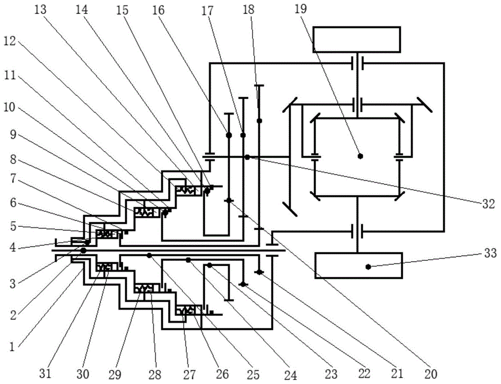
FIG. 3 is a schematic view of a stepped three-speed clutch
Reference numbers in the figures: 1, a shell; 2, an input shaft; 3, conveying the oil pipe; 4, a first-gear return spring; 5 a first gear piston; 6, a first-gear clutch plate; 7, a first-gear stop washer; 8 a second-gear return spring; 9 a second gear piston; a 10 second-gear clutch plate; 11 a second gear stop washer; 12 a third-gear return spring; 13 a third-gear piston; 14 a third gear clutch plate; 15 a third stop washer; 16 third gear far gear; 17 a second gear far gear; 18 first gear far gear; 19 a differential; 20 a third gear ring gear; 21 a first gear ring gear; 22 a second gear ring gear; 23 three-gear shaft; 24 second gear shafts; 25 a shift shaft; 26 a third-gear hydraulic cavity; 27 a third-gear sealing gasket; 28 a second-gear hydraulic cavity; 29 a second-gear sealing gasket; 30 first-gear hydraulic chambers; 31, a first-grade sealing gasket; 32 an output shaft; 33 wheels.
Detailed Description
The invention will be further explained with reference to fig. 1 and the specific embodiment, and fig. 1 is a schematic structural diagram of a three-gear stepped clutch according to the present invention. The hydraulic clutch comprises a shell 1, an input shaft 2, an oil delivery pipe 3, a first-gear return spring 4, a first-gear piston 5, a first-gear clutch plate 6, a first-gear stop washer 7, a second-gear return spring 8, a second-gear piston 9, a second-gear clutch plate 10, a second-gear stop washer 11, a third-gear return spring 12, a third-gear piston 13, a third-gear clutch plate 14, a third-gear stop washer 15, a third-gear far gear 16, a second-gear far gear 17, a first-gear far gear 18, a differential 19, a third-gear ring gear 20, a first-gear ring gear 21, a second-gear ring gear 22, a third-gear shaft 23, a second-gear shaft 24, a first-gear shaft 25, a third-gear hydraulic cavity 26, a third-gear sealing washer 27, a second-gear hydraulic cavity 28, a second-gear sealing washer 29, a first-gear hydraulic cavity 30, a first-gear sealing washer 31, an output shaft 32 and wheels 33. The first gear shaft 25, the second gear shaft 24 and the third gear shaft 23 are hollow shafts and are respectively fixedly connected with the third gear ring 20, the second gear ring 22 and the first gear ring 21, the second gear shaft 24 is nested outside the first gear shaft 25, and the third gear shaft 23 is nested outside the second gear shaft; the clutch structure is coaxially connected with the input shaft 2, the first gear return spring 4, the second gear return spring 8 and the third gear return spring 12 are respectively connected with the first gear piston 5, the second gear piston 9 and the third gear piston 13, and the first gear piston 5, the second gear piston 9 and the third gear piston 13 are respectively connected with the upper wall and the lower wall of the first gear hydraulic cavity 30, the second gear hydraulic cavity 28 and the third gear hydraulic cavity 26; the first gear stop washer 7, the second gear stop washer 15 and the third gear stop washer 27 are coaxially embedded behind the first gear clutch plate 6, the second gear clutch plate 10 and the third gear clutch plate 14 respectively; the first gear far gear 18, the second gear far gear 17 and the third gear far gear 16 are respectively meshed with the first gear ring 21, the second gear ring 22 and the third gear ring 20; the first gear sealing washer 31, the second gear sealing washer 29 and the third gear sealing washer 27 are respectively embedded on two sides of each gear oil delivery hole in a coaxial manner.
The working principle of the invention is as follows:
1. first gear
When hydraulic oil enters the first-gear hydraulic cavity 30 through the oil conveying pipe 3, the first-gear piston 5 moves rightwards, the first-gear clutch plate 6 and the first-gear shaft 25 are fixed together, the input shaft 2 transmits power to the first-gear shaft 25 through the first-gear clutch, the first-gear shaft 25 is fixedly connected with the first-gear ring 21 to drive the first-gear ring 21 to rotate, the first-gear ring 21 is in meshing transmission with the first-gear far gear 18 to transmit the power to the first-gear far gear 18, the first-gear far gear 18 drives the output shaft 32 to rotate, and the output shaft 32 outputs the power to wheels 33 through the differential 19.
2. Second gear
When hydraulic oil enters a second-gear hydraulic cavity 28 through an oil conveying pipe 3, a second-gear piston 9 moves rightwards, a second-gear clutch plate 10 and a second-gear shaft 24 are fixed together, an input shaft 2 transmits power to the second-gear shaft 24 through a second-gear clutch, the second-gear shaft 24 is fixedly connected with a second-gear ring gear 22 to drive the second-gear ring gear 22 to rotate, the second-gear ring gear 22 is in meshing transmission with a second-gear far gear 17 to transmit the power to the second-gear far gear 17, the second-gear far gear 17 drives an output shaft 32 to rotate, and the output shaft 32 outputs the power to wheels 33 through a differential 19.
3. Three-gear
When hydraulic oil enters a third-gear hydraulic cavity 26 through an oil conveying pipe 3, a third-gear piston 13 moves rightwards, a third-gear clutch plate 14 and a third-gear shaft 23 are fixed together, power is transmitted to the third-gear shaft 23 through a third-gear clutch by an input shaft 2, the third-gear shaft 23 is fixedly connected with a third-gear ring gear 20 to drive the third-gear ring gear 20 to rotate, the third-gear ring gear 20 is in meshing transmission with a third-gear far gear 16 to transmit the power to the third-gear far gear 16, the third-gear far gear 16 drives an output shaft 32 to rotate, and the output shaft 32 outputs the power to wheels 33 through a differential 19.
4. Neutral position
Hydraulic oil is not contained in the oil conveying pipe 3, the first-gear return spring 4, the second-gear return spring 8 and the third-gear return spring 12 are all located at initial positions, the first-gear clutch plate 6, the second-gear clutch plate 10 and the third-gear clutch plate 14 are not fixedly connected with the first-gear shaft 25, the second-gear shaft 24 and the third-gear shaft 23, the input shaft 2 cannot transmit power to each gear shaft, and the mechanism is in a neutral state.
5. Shifting (take first gear and second gear as an example)
(1) First gear shifting and second gear shifting
Withdrawing the hydraulic oil in the first-gear hydraulic chamber 30, returning the first-gear piston 5 to the initial position through the first-gear return spring 4, and disconnecting the first-gear clutch plate 6 from the first-gear shaft 25; and hydraulic oil is controlled to enter a second-gear hydraulic cavity 28, a second-gear piston 9 moves rightwards, a second-gear clutch plate 10 is fixedly connected with a second-gear shaft 24, and the second-gear mechanism works.
(2) Two-gear shifting
The hydraulic oil in the second gear hydraulic cavity 28 is withdrawn, the second gear piston 9 returns to the initial position through the second gear return spring 8, and the second gear clutch plate 10 is not connected with the second gear shaft 24; the hydraulic oil is controlled to enter the first gear hydraulic cavity 30, the first gear piston 5 moves rightwards, the first gear clutch plate 6 is fixedly connected with the first gear shaft 25, and the first gear of the mechanism works.