Standby charging device for electric automobile
Technical Field
The invention belongs to the field of new energy automobiles, relates to an automobile cleaning device, and particularly relates to a standby charging device for an electric automobile.
Background
The spare charging device of the electric automobile mainly solves the problem that the power supply of the electric automobile is accidentally consumed and nearby charging piles are not arranged by carrying a spare charging battery along with the automobile, but the spare charging battery is inconvenient to carry. For this reason, long-term research has been conducted, and various solutions have been proposed.
For example, chinese patent literature discloses a transportation device for a new energy automobile battery [ application No.: 201810290789.7], the power distribution box comprises a box body, the spout has all been seted up to the center department of box inner chamber both sides, the inner chamber sliding connection of spout has the slide bar, the inboard of slide bar runs through spout and fixedly connected with and places the case, it has the case lid through loose axle swing joint to place the left top of case, the right side fixedly connected with gag lever post of case lid bottom. According to the invention, through the matching of the box body, the sliding groove, the sliding rod, the placing box, the box cover, the limiting rod, the first fixing block, the limiting groove, the first clamping rod, the fixing pin, the supporting seat, the fixing seat, the buffer spring, the buffer head, the push rod, the shock absorber, the shock absorbing spring and the cover plate, the shock absorbing treatment can be carried out on the new energy automobile battery, meanwhile, the sealing performance of the transportation device is also enhanced, the use effect of the transportation device is enhanced, and the problem of poor use effect of the existing transportation device is solved.
Above-mentioned scheme battery body dismantles the difficulty, needs a plurality of steps to accomplish the installation and the dismantlement of battery, has improved operating personnel's intensity of labour.
Disclosure of Invention
The invention aims to solve the problems and provides a standby charging device for an electric automobile, which can easily complete the installation and the disassembly of a battery body, has a simple operation method and reduces the labor intensity of operators.
In order to achieve the purpose, the invention adopts the following technical scheme: this reserve charging device of electric automobile includes the frame, its characterized in that: the battery protection device is characterized in that a moving mechanism is arranged on one side of the rack, a control mechanism for controlling the moving mechanism to operate is arranged at one end of the moving mechanism, a buffer mechanism for placing and protecting a battery is arranged on the other side of the rack, an auxiliary mechanism for assisting the battery to be detached is arranged at one end of the buffer mechanism, a fixing mechanism is arranged at the other end of the buffer mechanism, and a handle mechanism is arranged at one end of the rack.
The auxiliary mechanism is creatively designed, so that the battery can be simply and effectively separated from the rack body, the battery can be conveniently detached by an operator, the battery replacing process is simplified, and the labor intensity of the operator is reduced.
In foretell reserve charging device of electric automobile, control mechanism includes the control lever, frame one end is equipped with first cavity, the control lever is located in the first cavity, be equipped with first limiting plate in the middle of the control lever, the control lever upper end extends to first cavity upside is equipped with first clamp plate, the control lever lower extreme extremely frame one side is equipped with the teeth of a cogwheel, teeth of a cogwheel one side be equipped with the gear of teeth of a cogwheel meshing, the gear in-connection has first rotation axis.
In foretell electric automobile spare charging device, moving mechanism includes first band pulley, first band pulley is located in the middle of the first rotation axis, first band pulley outer pot head is equipped with the drive belt, another pot head of drive belt is equipped with the second band pulley, second band pulley in-connection has the second rotation axis, first rotation axis with second rotation axis both ends respectively are equipped with a plurality of evenly distributed's undercarriage, undercarriage one end is equipped with first branch, be equipped with the tyre frame in the middle of the first branch, first branch one end is equipped with the nut, the nut with first branch screw thread closes soon, the nut with be equipped with the gasket between the tyre frame, the tyre frame other end is equipped with the tire, the tire through first round pin with tyre frame rotatable coupling.
In the standby charging device for the electric automobile, the buffering mechanism comprises a base, a first groove is formed in one side of the frame, a plurality of uniformly distributed second grooves are formed in one end of the first groove, the base is arranged in the first groove, one end of the base is matched with a round pipe of the second groove, one end of the round pipe is arranged in the second groove, a second supporting rod is arranged in the second groove, one end of the second supporting rod is arranged in the round pipe and provided with a sealing plate, a plurality of uniformly distributed through holes are formed in the sealing plate, a first spring is arranged at the outer end of the round pipe, the other end of the first spring is arranged on the bottom surface of the second groove, buffering plates are uniformly distributed at two ends of the inner wall of the base respectively, and a plurality of uniformly distributed second springs are arranged between the buffering plates and the base.
In the spare charging device for the electric vehicle, the auxiliary mechanism comprises a rod, a third groove is arranged on one side of the frame, a third supporting rod is arranged in the third groove, the middle of the rod is arranged in the middle of the third supporting rod, a first telescopic pipe is arranged on one side of the rod, an inner cavity is arranged at one end of the first telescopic pipe, a second limiting plate is arranged in the inner cavity at one end of the rod, a first rotating frame is arranged at the other end of the first telescopic pipe, the first rotating frame is rotatably connected with the first telescopic pipe through a second pin, a tray is arranged at the other end of the first rotating frame, first sliding blocks are respectively arranged on two sides of the tray, first limiting frames are respectively arranged at two ends of the third groove, a first sliding groove is arranged in the first limiting frame, the first sliding blocks are arranged in the first sliding groove and can slide relatively, and a second rotating frame is arranged at the other end of the rod, the second rotating frame is rotatably connected with the lever through a third pin, a second pressing plate is arranged at one end of the second rotating frame, a notch is formed in one side of the base, and when the second pressing plate is acted by an external force, the tray is moved to the other end of the base through the notch in the third groove.
In the spare charging device for an electric vehicle, the fixing mechanism comprises a fixing frame, the other end of the base is provided with a second limiting frame which is symmetrically distributed, the second limiting frame is arranged at the other side of the base, the fixing frame is arranged in the middle of the second limiting frame, one end of the second limiting frame is provided with a second chute, two ends of the fixing frame are respectively provided with a second slider, the second sliders are arranged in the second chutes and can slide relatively, a third spring is arranged between the second sliders and the second limiting frame, one side of the fixing frame is provided with a fourth groove, two ends of the inner wall of the fourth groove are respectively provided with a fourth supporting rod, a fixing plate is arranged in the fourth groove and can be rotatably connected with the fourth supporting rods, two ends of the fourth groove are respectively provided with a third chute, one side of the fixing frame is provided with a baffle, two ends of the baffle are arranged in the third chute and can slide relatively, when the baffle moves to one end of the third sliding chute, one end of the baffle is attached to one end of the fixing plate.
In the above-mentioned spare charging device for an electric vehicle, the handle mechanism includes a first telescopic tube, a plurality of second cavities are uniformly distributed on the other side of the frame, one end of the first telescopic tube is disposed in the second cavity, one end of the first telescopic tube is provided with a first platform, two sides of the first platform are respectively provided with a first flat plate, a fourth spring is disposed between the first flat plate and the first platform, the other end of the first flat plate is provided with a first convex block, two ends of the inner wall of the second cavity are respectively provided with a fourth sliding slot, the other end of the first convex block passes through the first telescopic tube and is disposed in the fourth sliding slot, the other end of the first telescopic tube is provided with a second telescopic tube, one end of the second telescopic tube is provided with a second platform, two sides of the second platform are respectively provided with a second flat plate, and a fifth spring is disposed between the second flat plate and the second platform, the other end of the second flat plate is provided with a second convex block, the two ends of the inner wall of the first telescopic pipe are respectively provided with a fifth sliding groove, one end of the second convex block penetrates through the second telescopic pipe and is arranged in the fifth sliding groove, and the other end of the second telescopic pipe is provided with a handle.
Compared with the prior art, the invention has the advantages that:
1. the moving mechanism in the invention improves the moving capability of the invention and can move towards any direction, so that the invention is quicker and more labor-saving in the carrying process, the labor intensity of operators is reduced, and the convenience of the invention is improved.
2. The control mechanism controls the lifting of the moving mechanism by driving the control rod to move up and down, and the moving mechanism can be folded when the control rod does not move, so that the movable type lifting device is stably placed on a plane, the operation method is simple, and the practicability of the movable type lifting device is improved.
3. The buffer mechanism can protect the battery body in the carrying process of the invention, prevent the battery from colliding with the frame in the moving process to damage the battery, and improve the practicability of the invention.
4. The auxiliary mechanism can lift the battery to separate the battery from the base, so that the battery is convenient to replace or dismantle, and meanwhile, the auxiliary mechanism adopts a labor-saving structure, so that the battery can be lifted more easily, and the labor intensity of operators is reduced.
5. The handle mechanism can provide a handle with telescopic length for operators to use, the length of the handle can be freely adjusted according to actual use conditions, the handle mechanism can be used in cooperation with the moving mechanism to move the handle mechanism more conveniently, and the practicability of the handle mechanism is improved.
Drawings
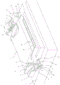
Fig. 1 is a front view of a backup charging device for an electric vehicle according to the present invention.
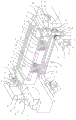
Fig. 2 is a bottom view of the backup charging device for an electric vehicle according to the present invention.
Fig. 3 is a partial sectional view of a backup charging device for an electric vehicle according to the present invention.
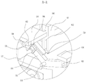
Fig. 4 is a partial sectional view of a section a of the backup charging device a for an electric vehicle according to the present invention.
Fig. 5 is a partial cross-sectional view of a section B of the backup charging device for an electric vehicle according to the present invention.
Fig. 6 is a partial cross-sectional view of a cross section of a backup charging device C for an electric vehicle according to the present invention.
In the figure, 1, a frame; 2. a battery; 10. a control mechanism; 11. a control lever; 12. a first cavity; 13. a first platen; 14. a first limiting plate; 15. gear teeth; 16. a gear; 17. a first rotating shaft; 20. a moving mechanism; 21. a first pulley; 22. a transmission belt; 23. a second pulley; 24. a second rotation shaft; 25. a landing gear; 26. a first support bar; 27. a tire frame; 28. a nut; 29. a gasket; 30. a tire; 31. a first pin; 40. a buffer mechanism; 41. a base; 42. a first groove; 43. a second groove; 44. a circular tube; 45. a second support bar; 46. a sealing plate; 47. a through hole; 48. a first spring; 49. a buffer plate; 49a, a second spring; 50. an auxiliary mechanism; 51. a lever; 52. a third groove; 53. a third support bar; 54. a second limiting plate; 55. a first telescopic tube; 56. an inner cavity; 57. a first rotating frame; 58. a tray; 59. a second pin; 60. a first slider; 61. a first limit bracket; 62. a first chute; 63. a second rotating frame; 64. a second platen; 65. a notch; 70. a fixing mechanism; 71. a fixed mount; 71a, a second slider; 72. a second limiting frame; 73. a second chute; 74. a third spring; 75. a fourth groove; 76. a fourth strut; 77. a fixing plate; 78. a third chute; 79. a baffle plate; 80. a handle mechanism; 81. a first telescopic tube; 82. a second cavity; 83. a first platform; 84. a first plate; 85. a fourth spring; 86. a first bump; 87. a fourth chute; 88. a second telescopic tube; 89. a second platform; 90. a second plate; 91. a fifth spring; 92. a second bump; 93. a fifth chute; 94. a handle.
Detailed Description
As shown in fig. 1 and fig. 2, the standby charging device for an electric vehicle of the present invention includes a frame 1, a moving mechanism 20 is disposed at a lower side of the frame 1, a control mechanism 10 for controlling the operation of the moving mechanism 20 is disposed at a left end of the moving mechanism 20, a buffer mechanism 40 for placing and protecting the battery 2 is disposed at an upper side of the frame 1, an auxiliary mechanism 60 for assisting the detachment of the battery 2 is disposed at a left end of the buffer mechanism 40, a fixing mechanism 70 is disposed at a right end of the buffer mechanism 40, and a handle mechanism 80 is disposed at a right end of the frame 1.
As shown in fig. 1 to 3, the control mechanism 10 includes a control rod 11, a first cavity 12 is provided at the left end of the rack 1, the control rod 11 is provided in the first cavity 12, a first limiting plate 14 is provided in the middle of the control rod 11, the upper end of the control rod 11 extends to the upper side of the first cavity 12 and is provided with a first pressing plate 13, the lower end of the control rod 11 extends to the lower side of the rack 1 and is provided with a gear tooth 15, a gear 16 engaged with the gear tooth 15 is provided at the right side of the gear tooth 15, a first rotating shaft 17 is connected in the gear 16, the gear 16 rotates synchronously with the first rotating shaft 17 through interference fit, and the first rotating shaft 17 is rotatably connected with the rack 1 through a bearing. The control mechanism 10 can lower the moving mechanism 20 by driving the control rod 11 to move downwards, drive the control rod 11 to move upwards to retract the moving mechanism 20, and retract the moving mechanism 20 when the control rod is not moved, so that the invention is stably placed on a plane, the operation method is simple, and the practicability of the invention is improved.
The moving mechanism 20 comprises a first belt wheel 21, the first belt wheel 21 is arranged in the middle of a first rotating shaft 17, the first belt wheel 21 rotates synchronously with the first rotating shaft 17 through interference fit, a transmission belt 22 is sleeved at the outer end of the first belt wheel 21, a second belt wheel 23 is sleeved at the right end of the transmission belt 22, a second rotating shaft 24 is connected in the second belt wheel 23, the second belt wheel 23 rotates synchronously with the second rotating shaft 24 through interference fit, the second rotating shaft 24 is rotatably connected with the frame 1 through a bearing, two ends of the first rotating shaft 17 and the second rotating shaft 24 are respectively provided with two landing gears 25 which are uniformly distributed, the landing gears 25 on the first rotating shaft 17 and the second rotating shaft 24 rotate synchronously through interference fit, a first supporting rod 26 is arranged at the lower end of the landing gear 25, a tire frame 27 is arranged in the middle of the first supporting rod 26, the tire frame 27 is rotatably connected with the first supporting rod 26 through a bearing, a nut 28 is arranged at the bottom end of the first supporting rod 26, the nut 28 is screwed with the first support rod 26, a gasket 29 is arranged between the nut 28 and the tyre frame 27, a tyre 30 is arranged at the lower end of the tyre frame 27, and the tyre 30 is rotatably connected with the tyre frame 27 through a first pin 31. The moving mechanism 20 improves the moving capability of the invention and can move towards any direction, so that the invention is quicker and more labor-saving in the carrying process, the labor intensity of operators is reduced, and the convenience of the invention is improved.
Buffer gear 40 includes base 41, 1 upside of frame is equipped with first recess 42, first recess 42 lower extreme is equipped with two at least evenly distributed's second recess 43, base 41 is located in first recess 42, base 41 lower extreme is equipped with the pipe 44 with second recess 43 looks adaptation, pipe 44 lower extreme is located in second recess 43, pipe 44 external diameter is less than second recess 43 internal diameter, be equipped with second branch 45 in the second recess 43, second branch 45 upper end is located in pipe 44 and is equipped with closing plate 46, be equipped with four at least evenly distributed's through-hole 47 on the closing plate 46, through-hole 47 internal diameter is less than 8 millimeters, the pipe 44 outside is equipped with first spring 48, second recess 43 bottom surface is located to first spring 48 lower extreme, base 41 inner wall both ends respectively are equipped with evenly distributed's buffer board 49, be equipped with two at least evenly distributed's second spring 49a between buffer board 49 and the base 41. The buffer mechanism 40 can protect the battery 2 during carrying of the present invention, prevent the battery 2 from colliding with the frame 1 during moving to damage the battery 2, and improve the practicability of the present invention.
As shown in fig. 1, 3 and 4, the auxiliary mechanism 50 includes a rod 51, a third groove 52 is disposed on the left side of the frame 1, a third support 53 is disposed in the third groove 52, the middle of the rod 51 is disposed in the middle of the third support 53, the rod 51 is rotatably connected to the third support 53 through a bearing, the length of the left end of the rod 51 is greater than the length of the right end, a first extension tube 55 is disposed on the right side of the rod 51, an inner cavity 56 is disposed on the left end of the first extension tube 55, the right end of the rod 51 is disposed in the inner cavity 56 and provided with a second limiting plate 54, a first rotating frame 57 is disposed on the right end of the first extension tube 55, the first rotating frame 57 is rotatably connected to the first extension tube 55 through a second pin 59, a tray 58 is disposed on the outer end of the first rotating frame 57, first sliding blocks 60 are disposed on both sides of the tray 58, first limiting frames 61 are disposed on both ends of the third groove 52, a first sliding block 62 is disposed in the first limiting frame 61, the first sliding block 60 is disposed in the first sliding block 62 and can slide relatively, the left end of the lever 51 is provided with a second rotating frame 63, the second rotating frame 63 is rotatably connected with the lever 51 through a third pin, the outer end of the second rotating frame 63 is provided with a second pressing plate 64, the left side of the base 41 is provided with a notch 65, and when the second pressing plate 64 is acted by external force, the tray 58 moves to the upper end of the base 41 through the notch 65 from the third groove 52. The auxiliary mechanism 50 can lift the battery 2, so that the battery 2 is separated from the base 41, the battery 2 is convenient to replace or dismantle, meanwhile, the auxiliary mechanism 50 adopts a labor-saving structure, the battery 2 can be lifted more easily, and the labor intensity of operators is reduced.
As shown in fig. 1, 3 and 5, the fixing mechanism 70 includes a fixing frame 71, the right end of the base 41 is provided with a second limiting frame 72 which is symmetrically distributed, the second limiting frame 72 is arranged on the upper side of the base 41, the fixing frame 71 is arranged in the middle of the second limiting frame 72, the inner side of the second limiting frame 72 is provided with a second sliding slot 73, two ends of the fixing frame 71 are respectively provided with a second sliding block 71a, the second sliding block 71a is arranged in the second sliding slot 73 and can relatively slide, a third spring 74 is arranged between the second sliding block 71a and the second limiting frame 72, the left side of the fixing frame 71 is provided with a fourth groove 75, two ends of the inner wall of the fourth groove 75 are respectively provided with a fourth supporting rod 76, a fixing plate 77 is arranged in the fourth groove 75, the fixing plate 77 is rotatably connected with the fourth supporting rod 76 through clearance fit, two ends of the fourth groove 75 are respectively provided with a third sliding slot 78, the upper side of the fixing frame 71 is provided with a baffle 79, two ends of the baffle 79 are arranged in the third sliding slot 78 and can relatively slide, when the baffle 79 moves to the left end of the third sliding chute 78, the lower end of the baffle 79 is attached to the upper end of the fixing plate 77.
As shown in fig. 1, 2 and 6, the handle mechanism 80 comprises a first extension tube 81, two second cavities 82 are uniformly distributed at the right side of the frame 1, the lower end of the first extension tube 81 is arranged in the second cavities 82, a first platform 83 is arranged at the lower end of the first extension tube 81, first plates 84 are respectively arranged at two sides of the first platform 83, fourth springs 85 are arranged between the first plates 84 and the first platforms 83, a first bump 86 is arranged at the outer end of the first plate 84, fourth sliding chutes 87 are respectively arranged at two ends of the inner wall of the second cavity 82, the outer end of the first bump 86 passes through the first extension tube 81 and is arranged in the fourth sliding chutes 87, a second extension tube 88 is arranged at the upper end of the first extension tube 81, the diameter of the second extension tube 88 is smaller than that of the first extension tube 81, a second platform 89 is arranged at the lower end of the second extension tube 88, second plates 90 are respectively arranged at two sides of the second platform 89, a fifth spring 91 is arranged between the second plate 90 and the second platform 89, the outer end of the second flat plate 90 is provided with a second projection 92, both ends of the inner wall of the first extension tube 81 are respectively provided with a fifth sliding slot 93, the outer end of the second projection 92 passes through the second extension tube 88 and is arranged in the fifth sliding slot 93, the upper end of the second extension tube 88 is provided with a handle 94, the lower end of the handle 94 is arranged in the front and rear extension tubes 88, and the handle 94 is fixedly connected with the second extension tube 88 through interference fit. The handle mechanism 80 can provide a handle 94 with a telescopic length for an operator to use, the length of the handle 94 can be freely adjusted according to the actual use condition, the invention can be more conveniently moved by matching with the moving mechanism 20, and the practicability of the invention is improved.
The specific operation mode of the specific embodiment of the invention is as follows: when the invention needs to be moved, the first pressing plate 13 is pressed, the control rod 11 moves downwards along with the first pressing plate 13, the gear teeth 15 on the control rod 11 drive the gear 16 engaged with the gear teeth 15 to rotate in the process of moving downwards, the gear 16 drives the first rotating shaft 17 to rotate, the first rotating shaft 17 drives the first belt pulley 21 to rotate, the first belt pulley 21 transmits power to the second belt pulley 23 through the transmission belt 22, the second belt pulley 23 drives the second rotating shaft 24 to rotate, at this time, the first rotating shaft 17 and the second rotating shaft 24 simultaneously drive the undercarriage 25 to rotate anticlockwise, the undercarriage 25 is converted from the retracted state to the dropped state, the undercarriage 25 drives the tire rack 27 to rotate the tire 30 to the outer side of the lower end of the frame 1, the rotatable connection of the tire rack 27 and the first supporting rod 26 enables the tire 30 to freely change the orientation, the invention can move towards all directions, and simultaneously the handle 94 is pulled upwards, the handle 94 drives the second extension tube 88 to move upwards, when the second bump 92 is driven by the second extension tube 88 to move to the top end of the fifth sliding groove 93, the second bump 92 pushes the first extension tube 81 to move upwards, the invention can be pushed to move by the handle 94 after the handle 94 is adjusted to a proper height, the handle 94 can be pushed downwards to retract to the bottom end after the movement is completed, meanwhile, the first pressing plate 13 is pulled upwards to drive the landing gear 25 to rotate clockwise, the tire 30 is retracted to the inner side of the lower end of the rack 1, when the battery 2 is installed, the battery 2 is placed into the base 41, two ends of the battery 2 are attached to the buffer plate 49, the fixing plate 77 is stirred to rotate anticlockwise until the lower end of the fixing plate 77 is attached to the upper end of the battery 2, the baffle 79 is moved leftwards until the left end of the third sliding groove 78, the lower end of the baffle 79 is attached to the upper end of the fixing plate 77, the fixing plate 77 is fixed, the battery 2 is fixed in the base 41, when the invention is vibrated up and down, the round tube 44 presses the first spring 48 and moves downwards, the air between the sealing plate 46 and the round tube 44 is pressed and slowly passes through the through hole 47, the air and the first spring 48 jointly play a role of praying the buffering base 41, when the battery 2 needs to be disassembled, the baffle 79 moves rightwards until the right end of the third sliding groove 78, the fixing plate 77 is rotated clockwise to enable the fixing plate 77 to be away from the battery 2, at the moment, the second pressing plate 64 is pressed, the second pressing plate 64 pushes the left end of the rod 51 to move downwards through the second rotating frame 63, the right end of the rod 51 moves upwards along with the rod, the first telescopic tube 55 connected with the right end of the rod 51 moves upwards along with the rod, the second limiting plate 54 slides in the inner cavity 56, the first telescopic tube 55 pushes the tray 58 to move upwards through the first rotating frame 57, the upper end of the tray 58 is contacted with the lower end of the battery 2 and pushes the battery 2 to be separated from the base 41, and the battery 2 can be disassembled.
The specific embodiments described herein are merely illustrative of the invention. Various modifications or additions may be made to the described embodiments or alternatives may be employed by those skilled in the art without departing from the spirit or ambit of the invention as defined in the appended claims.
Although the terms gear teeth, first limiting plate, tire frame, through hole, sealing plate, buffer plate, circular tube, lever, notch, fixing frame, first platform, first projection, fixing plate, baffle plate, etc. are used more herein, the possibility of using other terms is not excluded. These terms are used merely to more conveniently describe and explain the nature of the present invention and they are to be interpreted as any additional limitation which is not in accordance with the spirit of the present invention.