CN111804187A - Automatic glue making device - Google Patents
Automatic glue making device Download PDFInfo
- Publication number
- CN111804187A CN111804187A CN202010723029.8A CN202010723029A CN111804187A CN 111804187 A CN111804187 A CN 111804187A CN 202010723029 A CN202010723029 A CN 202010723029A CN 111804187 A CN111804187 A CN 111804187A
- Authority
- CN
- China
- Prior art keywords
- tank
- stirring tank
- support frame
- communicated
- glue
- Prior art date
- Legal status (The legal status is an assumption and is not a legal conclusion. Google has not performed a legal analysis and makes no representation as to the accuracy of the status listed.)
- Pending
Links
Images


Classifications
-
- B—PERFORMING OPERATIONS; TRANSPORTING
- B01—PHYSICAL OR CHEMICAL PROCESSES OR APPARATUS IN GENERAL
- B01F—MIXING, e.g. DISSOLVING, EMULSIFYING OR DISPERSING
- B01F27/00—Mixers with rotary stirring devices in fixed receptacles; Kneaders
- B01F27/05—Stirrers
- B01F27/11—Stirrers characterised by the configuration of the stirrers
- B01F27/19—Stirrers with two or more mixing elements mounted in sequence on the same axis
- B01F27/192—Stirrers with two or more mixing elements mounted in sequence on the same axis with dissimilar elements
-
- B—PERFORMING OPERATIONS; TRANSPORTING
- B01—PHYSICAL OR CHEMICAL PROCESSES OR APPARATUS IN GENERAL
- B01F—MIXING, e.g. DISSOLVING, EMULSIFYING OR DISPERSING
- B01F27/00—Mixers with rotary stirring devices in fixed receptacles; Kneaders
- B01F27/80—Mixers with rotary stirring devices in fixed receptacles; Kneaders with stirrers rotating about a substantially vertical axis
- B01F27/90—Mixers with rotary stirring devices in fixed receptacles; Kneaders with stirrers rotating about a substantially vertical axis with paddles or arms
-
- B—PERFORMING OPERATIONS; TRANSPORTING
- B01—PHYSICAL OR CHEMICAL PROCESSES OR APPARATUS IN GENERAL
- B01F—MIXING, e.g. DISSOLVING, EMULSIFYING OR DISPERSING
- B01F27/00—Mixers with rotary stirring devices in fixed receptacles; Kneaders
- B01F27/80—Mixers with rotary stirring devices in fixed receptacles; Kneaders with stirrers rotating about a substantially vertical axis
- B01F27/93—Mixers with rotary stirring devices in fixed receptacles; Kneaders with stirrers rotating about a substantially vertical axis with rotary discs
-
- B—PERFORMING OPERATIONS; TRANSPORTING
- B01—PHYSICAL OR CHEMICAL PROCESSES OR APPARATUS IN GENERAL
- B01F—MIXING, e.g. DISSOLVING, EMULSIFYING OR DISPERSING
- B01F35/00—Accessories for mixers; Auxiliary operations or auxiliary devices; Parts or details of general application
- B01F35/10—Maintenance of mixers
- B01F35/12—Maintenance of mixers using mechanical means
-
- B—PERFORMING OPERATIONS; TRANSPORTING
- B01—PHYSICAL OR CHEMICAL PROCESSES OR APPARATUS IN GENERAL
- B01F—MIXING, e.g. DISSOLVING, EMULSIFYING OR DISPERSING
- B01F35/00—Accessories for mixers; Auxiliary operations or auxiliary devices; Parts or details of general application
- B01F35/71—Feed mechanisms
- B01F35/712—Feed mechanisms for feeding fluids
-
- B—PERFORMING OPERATIONS; TRANSPORTING
- B01—PHYSICAL OR CHEMICAL PROCESSES OR APPARATUS IN GENERAL
- B01F—MIXING, e.g. DISSOLVING, EMULSIFYING OR DISPERSING
- B01F35/00—Accessories for mixers; Auxiliary operations or auxiliary devices; Parts or details of general application
- B01F35/71—Feed mechanisms
- B01F35/717—Feed mechanisms characterised by the means for feeding the components to the mixer
- B01F35/71775—Feed mechanisms characterised by the means for feeding the components to the mixer using helical screws
-
- B—PERFORMING OPERATIONS; TRANSPORTING
- B01—PHYSICAL OR CHEMICAL PROCESSES OR APPARATUS IN GENERAL
- B01F—MIXING, e.g. DISSOLVING, EMULSIFYING OR DISPERSING
- B01F35/00—Accessories for mixers; Auxiliary operations or auxiliary devices; Parts or details of general application
- B01F35/71—Feed mechanisms
- B01F35/717—Feed mechanisms characterised by the means for feeding the components to the mixer
- B01F35/71815—Feed mechanisms characterised by the means for feeding the components to the mixer using vibrations, e.g. standing waves or ultrasonic vibrations
-
- B—PERFORMING OPERATIONS; TRANSPORTING
- B01—PHYSICAL OR CHEMICAL PROCESSES OR APPARATUS IN GENERAL
- B01F—MIXING, e.g. DISSOLVING, EMULSIFYING OR DISPERSING
- B01F35/00—Accessories for mixers; Auxiliary operations or auxiliary devices; Parts or details of general application
- B01F35/80—Forming a predetermined ratio of the substances to be mixed
- B01F35/88—Forming a predetermined ratio of the substances to be mixed by feeding the materials batchwise
- B01F35/881—Forming a predetermined ratio of the substances to be mixed by feeding the materials batchwise by weighing, e.g. with automatic discharge
-
- B—PERFORMING OPERATIONS; TRANSPORTING
- B01—PHYSICAL OR CHEMICAL PROCESSES OR APPARATUS IN GENERAL
- B01F—MIXING, e.g. DISSOLVING, EMULSIFYING OR DISPERSING
- B01F35/00—Accessories for mixers; Auxiliary operations or auxiliary devices; Parts or details of general application
- B01F35/90—Heating or cooling systems
- B01F35/91—Heating or cooling systems using gas or liquid injected into the material, e.g. using liquefied carbon dioxide or steam
-
- B—PERFORMING OPERATIONS; TRANSPORTING
- B01—PHYSICAL OR CHEMICAL PROCESSES OR APPARATUS IN GENERAL
- B01F—MIXING, e.g. DISSOLVING, EMULSIFYING OR DISPERSING
- B01F35/00—Accessories for mixers; Auxiliary operations or auxiliary devices; Parts or details of general application
- B01F35/90—Heating or cooling systems
- B01F2035/99—Heating
-
- B—PERFORMING OPERATIONS; TRANSPORTING
- B01—PHYSICAL OR CHEMICAL PROCESSES OR APPARATUS IN GENERAL
- B01F—MIXING, e.g. DISSOLVING, EMULSIFYING OR DISPERSING
- B01F2101/00—Mixing characterised by the nature of the mixed materials or by the application field
- B01F2101/36—Mixing of ingredients for adhesives or glues; Mixing adhesives and gas
Abstract
The invention discloses an automatic glue making device which comprises a support frame, wherein a main stirring tank and an auxiliary stirring tank are respectively arranged on the upper plate surface of the support frame, and a feeding hopper is arranged on one side of the main stirring tank; the lower part of the support frame is provided with a hot water tank communicated with a hot water pipe, the hot water pipe is communicated with a three-way temperature control valve, the other water inlet end of the three-way temperature control valve is connected with a tap water tank through a first cold water pipe, and the water outlet end of the three-way temperature control valve is communicated with the main stirring tank through a mixing water outlet pipe; the auxiliary stirring tank is communicated with the tap water tank through a second cold water pipe, the bottom of the auxiliary stirring tank is communicated with the main stirring tank through a liquid outlet pipe, and the bottom of the main stirring tank is communicated with the glue storage tank through a glue outlet pipe. The invention has simple structure, light weight, strong safety and high economy; the three-way temperature control valve is arranged to enable water entering the main stirring tank to be warm water with a set temperature, so that the influence of water temperature fluctuation on the performance of the glue is avoided, the stability of the performance of the prepared glue is ensured, and the qualification rate is high.
Description
Technical Field
The invention relates to the technical field of glue preparation devices, in particular to an automatic glue making device.
Background
Glue is commonly used in both real life and in industry, especially in the field of packaging technology. The raw materials need to be uniformly mixed in the glue preparation process, so the stirring tank is common equipment in a glue making machine, but the existing stirring tank is generally composed of a tank body and a stirring shaft, and because the glue has certain viscosity, the existing stirring tank generally has the condition of uneven stirring, and also easily causes the capsule in the glue to cause the deviation of the raw material ratio in the glue, thereby reducing the quality of the glue. In addition, the glue can stick on the inner wall in the process of stirring the glue, so that the glue yield is small, and the cleaning is troublesome. The addition of auxiliary materials in the existing glue making machine is directly added into a tank body after being weighed, the operation is troublesome, and workers need to manually weigh the auxiliary materials.
In addition, the temperature of water in a main tank of a glue making machine is preferably 30 ℃, the change of the water temperature can directly influence the performance of glue, the existing glue making machine is generally that cold water is directly injected into the main tank, then the hot water and the cold water are added into the main tank for neutralization through waste gas waste heat, so that the water temperature in the tank is difficult to control, the problem of higher or lower water is easy to occur, the performance of the glue is unstable, even the glue preparation fails, and resources are wasted.
Disclosure of Invention
In view of the above, the present invention provides an automatic glue-making device with simple structure, light weight, stable yield, good glue quality, and high economy, aiming at the defects of the prior art.
In order to achieve the purpose, the invention adopts the following technical scheme:
an automatic glue making device comprises a support frame, wherein two mounting holes and two feeding holes are formed in the upper plate surface of the support frame respectively, a main stirring tank and an auxiliary stirring tank are arranged in the mounting holes respectively, and a feeding device communicated with the main stirring tank is arranged on one side of the main stirring tank; a hot water tank communicated with a hot water pipe is arranged at the lower part of the support frame, a three-way temperature control valve is communicated with the hot water pipe, the other water inlet end of the three-way temperature control valve is connected with a tap water tank through a first cold water pipe, and the water outlet end of the three-way temperature control valve is communicated with the main stirring tank through a mixing water outlet pipe; the auxiliary stirring tanks are communicated with a tap water tank through second cold water pipes, the bottoms of the auxiliary stirring tanks are communicated with the main stirring tank through liquid outlet pipes, and the bottoms of the main stirring tank are communicated with a glue storage tank through glue outlet pipes; the outside of support frame be equipped with the flood dragon material loading machine that main agitator tank is linked together.
Aiming at the technical scheme, the auxiliary stirring tank is used for containing caustic soda, tap water enters the auxiliary stirring tank through the second cooling water pipe to liquefy the caustic soda, and the caustic soda entering the main stirring tank is more easily and uniformly mixed with other raw materials; adding warm water of 30 ℃ into the main stirring tank through a mixing water outlet pipe, then conveying starch into the main stirring tank through a dragon feeding machine for stirring, then adding caustic soda and continuing stirring; and then adding auxiliary materials through a feeding hopper, stirring, and finally enabling the prepared glue to flow out of the glue outlet pipe and enter the glue storage tank. The three-way temperature control valve is arranged to enable warm water with set temperature to directly enter the main stirring tank, so that the defect caused by water temperature fluctuation is avoided, and the stability of the performance of the glue is ensured.
Preferably, the feeding device comprises a material storage device fixed on one side of the main stirring tank and a weighing and discharging device arranged on the main stirring tank; the storage device comprises a support fixed on the support frame and a plurality of storage hoppers fixed on the support frame, wherein a discharge pipe is arranged at the lower part of each storage hopper, and a spiral conveying shaft driven by a storage motor is arranged in each discharge pipe; the weighing and blanking device comprises a support arranged above the feeding hole, a vibration table is arranged above the support, a feeding hopper corresponding to an outlet of the discharging pipe is connected above the vibration table through a bottom plate, pressure-sensitive sensors are respectively arranged at four corners between the vibration table and the bottom plate, and a bearing hole corresponding to the feeding hole is formed in the vibration table; the shielding mechanism is arranged at the position of the bearing hole at the bottom of the vibrating table and comprises a baffle arranged below the bearing hole, a rotating shaft is fixedly connected to one side of the baffle, one end of the rotating shaft is rotatably connected with the support, and the other end of the rotating shaft is connected with a shutter motor fixedly arranged on the support.
The feeding device realizes automatic addition of auxiliary materials by adopting an automatic weighing technology, does not need manual operation, and ensures that the glue making process is more convenient and the glue making efficiency is higher; the auxiliary materials are respectively arranged in the storage hoppers, when the auxiliary materials need to be added, the storage motor drives the spiral conveying shaft to rotate so as to push the auxiliary materials to the feed hopper from the discharge pipe, the pressure-sensitive sensor performs data weighing, when a set value is reached, the shutter motor rotates to drive the baffle plate to rotate outwards, the receiving hole is opened to add the auxiliary materials to the main stirring tank, and the purpose of automatically adding the auxiliary materials is achieved; the shaking table is opened the back at the baffle and is started, makes the auxiliary material in the feeder hopper all get into main agitator tank, avoids leaving over of auxiliary material.
Preferably, a conical blanking hopper is arranged on the feeding hole; the support is including fixed setting up slide rail on the support frame upper plate face and with slide rail matched with slider install the storage hopper on the slider. The addition of auxiliary materials is convenient.
Preferably, the main stirring tank and the auxiliary stirring tank respectively comprise a tank body, a tank cover is arranged above the tank body, and a stirring motor is fixedly arranged on the tank cover through a support; the stirring device is characterized in that a stirring rod is fixedly connected to an output shaft of the stirring motor, a high-speed shearing disc is arranged at the bottom of the stirring rod, a rotating disc is arranged at the upper part of the stirring rod, and a plurality of guide plates are arranged on the periphery of the rotating disc. Stirring motor drives rotary disk and guide plate and rotates, and the outside and the jar inner wall contact of guide plate can be scraped glue from jar inner wall at any time, avoid glue to solidify on jar inner wall, and the guide plate plays the effect of stirring water conservancy diversion simultaneously, makes jar peripheral liquid also can the intensive mixing.
The high-speed shearing disc is arranged to drive the liquid in the main tank to rotate up and down through high-speed rotation of the high-speed shearing disc, and simultaneously, the high-speed shearing disc performs spiral rotation, so that all components can be fully mixed and melted, and the formation of a wrapping object is avoided; the stirring of the stirring blades is replaced by the high-speed shearing disc, so that the situations of difficult cleaning and stirring blockage caused by the fact that raw materials or glue are stuck on the stirring blades are prevented, and meanwhile, the internal structure of the stirring tank is simpler, and the inside of the stirring tank is easier to clean; thereby make the whole weight of the jar body reduce owing to the simplified structure of puddler, make the removal of the jar body more convenient, the safety in utilization is higher. The combined action of the guide plate and the high-speed shearing disc promotes the whole mixture in the tank body to be stirred more uniformly, and promotes the raw materials to be fully mixed and dissolved.
Preferably, the periphery of the outer wall of the tank body is provided with a supporting leg for fixing the tank body on the supporting frame, the supporting leg is a U-shaped frame with an upward opening, and weight sensors are arranged between the supporting leg and the supporting frame. The landing leg is used for fixed agitator tank, can directly place the jar body and fix on the support frame, makes the installation of the jar body simpler, and weighing transducer is used for weighing the whole weight of main jar to can be used for controlling the addition amount of water feeding volume and raw materials.
Preferably, the cover comprises a crescent cover and a semicircular cover, and the crescent cover and the semicircular cover are connected through a hinge. The split type design of cover makes jar body use more convenient, makes things convenient for operating personnel to open the cover at any time and observes the internal condition of jar.
Preferably, a reinforcing ring is welded above the tank body; and a wedge-shaped rubber strip is arranged on one side of the guide plate, which is in contact with the inner wall of the tank body. The bearing capacity of the tank body is increased, and the safety of the stirring tank is improved; the rubber strip is used for scraping off the glue on the inner wall, so that raw materials or the glue are prevented from being stuck on the inner wall, the components of the glue are closer to a set value, and the quality of the glue is ensured.
Preferably, the power of the stirring motor is 18.5 kw. The glue can reach the optimal stirring state.
Preferably, centrifugal pumps are respectively arranged on the liquid outlet pipe, the mixing water outlet pipe and the rubber outlet pipe; and the first cold water pipe, the second cold water pipe and the hot water pipe are respectively provided with an electromagnetic valve.
Preferably, the bottom of support frame is equipped with the box that is used for adorning the controller, the controller is connected with centrifugal pump, solenoid valve, agitator motor, shutter motor, storage motor, weight sensor, pressure-sensitive sensor electricity.
The invention has the beneficial effects that:
the invention has the advantages of simple structure, light weight, strong safety, convenient installation and low cost. The economy is high; the effect makes the mixture more even between each raw materials of glue when high-speed shearing dish and guide plate, has avoided the appearance of wrapping up in the glue under the high-speed rotation condition of shearing the dish at high speed simultaneously, ensures that the ratio between each raw materials is more accurate in the glue, improves the quality of glue, shortens the churning time of glue, improves glue production efficiency. The guide plate can also avoid the deviation of the ingredients in the glue water caused by the fact that the substances in the tank are stuck to the inner wall of the tank, and the problem that the inner wall of the tank is difficult to clean is also solved. The three-way temperature control valve is arranged to enable water entering the main stirring tank to be warm water with a set temperature, so that the influence of water temperature fluctuation on the performance of the glue is avoided, the stability of the performance of the prepared glue is ensured, and the qualification rate is high.
Drawings
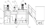
FIG. 1 is a perspective view of the present invention;
FIG. 2 is a side view of the present invention;
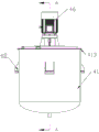
FIG. 3 is a perspective view of the main agitator tank;
FIG. 4 is a side view of the main agitator tank;
FIG. 5 is a cross-sectional view of the main agitator tank taken along the direction A-A;
FIG. 6 is a schematic structural view of a stocker;
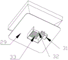
FIG. 7 is a schematic structural view of a weighing and blanking device;
fig. 8 is a perspective view of the weighing and blanking device.
In the figure: 1 support frame, 2 loading attachment, 3 vice agitator tanks, 4 main agitator tanks, 5 flood dragon material loading machines, 6 hot-water tanks, 7 hot-water line, 8 drain pipes, 9 first cold water pipe, 10 second cold water pipe, 11 rubber outlet pipe, 12 mix the outlet pipe, 13 tee bend temperature-sensing valve, 14 solenoid valves, 15 glue storage tank, 16 centrifugal pumps, 17 storage device, 18 unloader that weighs, 19 slide rails, 20 sliders, 21 hopper, 22 storage hopper, 23 discharging pipe, 24 spiral conveying axle, 25 storage motor, 26 feeder hopper, 27 bottom plate, 28 pressure-sensitive sensor, 29 shaking table, 30 support, 31 shutter motor, 32 pivot, 33 baffle, 41 jar body, 42 puddler, 43 cover, 44 high-speed shear dish, 45 connecting plate, 46 agitator motor, 47 guide plate, 48 landing leg, 49 rotary disk, 410 crescent moon lid, 411 semicircle lid, 412, 413 reinforcing ring, 414 rubber strip, 415 weighing sensor.
Detailed Description
The invention is further described below with reference to the figures and examples.
As shown in fig. 1-8, an automatic glue making device comprises a support frame 1, wherein two mounting holes and a feeding hole are respectively formed in the upper plate surface of the support frame 1, a main stirring tank 4 and an auxiliary stirring tank 3 are respectively arranged in the two mounting holes, and a conical blanking hopper 21 is arranged on the feeding hole.
The main agitator tank 4 is identical with the structure of vice agitator tank 3, includes jar body 41 respectively, and the welding has the reinforcing ring 413 in the top of jar body 41, is equipped with cover 43 in the top of reinforcing ring 413, and cover 43 includes crescent cover 410 and semicircle lid 411, and is connected through hinge 412 between crescent cover 410 and the semicircle lid 411. The tank cover 43 is fixedly provided with a stirring motor 46 through a connecting plate 45, and the power of the stirring motor 46 is 18.5 kw. The output shaft of the stirring motor 46 is fixedly connected with a stirring rod 42, the bottom of the stirring rod 42 is provided with a high-speed shearing disc 44, the upper part of the stirring rod 42 is provided with a rotating disc 49, the periphery of the rotating disc 49 is provided with a plurality of guide plates 47, and one side of the guide plates 47, which is in contact with the inner wall of the tank body 41, is provided with a wedge-shaped rubber strip 414. A connecting hole is arranged in the middle of the rotating disc 49, an internal thread is arranged in the connecting hole, an external thread is arranged outside the stirring rod 42, the stirring rod 42 and the rotating disc 49 are connected together through the connecting hole in a threaded mode, and a high-speed shearing disc 44 is arranged at the bottom of the stirring rod 42. The periphery of the outer wall of the tank 41 is provided with a leg 48 for fixing the tank 41 on the support frame 1, and the leg 48 is a U-shaped frame with an upward opening. A weight sensor 415 is provided between the leg 48 and the support 1.
A feeding device 2 communicated with the support frame 1 on one side of the main stirring tank 4 is arranged on the support frame; the feeding device 2 comprises a material storage device 17 fixed on one side of the main stirring tank and a weighing and blanking device arranged on the main stirring tank.
The storage device 17 comprises a support 30 fixed on the support frame and a plurality of storage hoppers 22 fixed on the support 30, a discharge pipe 23 is arranged at the lower part of each storage hopper 22, and a spiral conveying shaft 24 driven by a storage motor 25 is arranged in each discharge pipe 23. The bracket 30 comprises a slide rail 19 fixedly arranged on the upper plate surface of the support frame and a slide block 20 matched with the slide rail 19, and a storage hopper 22 is arranged on the slide block 20. The slide 20 can be moved manually in the slide rail 19 or by a motor.
The weighing and blanking device 18 comprises a bracket 30 arranged above the feeding hole, a vibration table 29 is arranged above the bracket 30, a feeding hopper 26 corresponding to the outlets of all discharging pipes 23 is connected above the vibration table 29 through a bottom plate 27, pressure-sensitive sensors 28 are respectively arranged at four corners between the vibration table 29 and the bottom plate 27, and bearing holes corresponding to the feeding hole are arranged on the vibration table 29; a shielding mechanism is provided at the position of the receiving hole at the bottom of the vibration table 29. The shielding mechanism comprises a baffle 33 arranged below the bearing hole, a rotating shaft 32 is fixedly connected to one side of the baffle 33, one end of the rotating shaft 32 is rotatably connected with the support 30, and the other end of the rotating shaft is fixedly connected with the output end of a shutter motor 31 fixedly arranged on the support 30.
The lower part of the support frame 1 is provided with a hot water tank 6 communicated with a hot water pipe 7 and a box body used for installing a controller. A three-way temperature control valve 13 is communicated with the hot water pipe 7, the other water inlet end of the three-way temperature control valve 13 is connected with a tap water tank through a first cold water pipe 9, and the water outlet end of the three-way temperature control valve 13 is communicated with a tank body 41 of the main stirring tank 4 through a mixing water outlet pipe 12; the auxiliary stirring tank 3 is communicated with a tap water tank through a second cold water pipe 10, the bottom of the auxiliary stirring tank 3 is communicated with the main stirring tank 4 through a liquid outlet pipe 8, and the bottom of the main stirring tank 4 is communicated with a glue storage tank 15 through a glue outlet pipe 11. A flood dragon feeding machine 5 communicated with the main stirring tank 4 is arranged on one side of the supporting frame 1.
The centrifugal pump 16, the electromagnetic valve 14, the stirring motor 46, the shutter motor 31, the storage motor 25, the weight sensor, the pressure-sensitive sensor 28, the heating rod and the liquid level sensor are all electrically connected with the controller.
Can also set up stair in one side of support frame, make things convenient for the staff to go the material loading and observe the condition on the support frame face. A hand washing sink can be arranged on the upper plate surface of the supporting frame.
The apparatus elements referred to in the above embodiments are, unless otherwise specified, conventional apparatus elements such as: centrifugal pump 16, solenoid valve 14, agitator motor 46, heating rod, level sensor, shutter motor 31, storage motor 25, weight sensor, pressure-sensitive sensor 28, controller and flood dragon material loading machine 5. The structural setting, operation or control modes related to the above are all the setting, operation or control modes which are conventional in the art, unless otherwise specified.
The working principle of the invention is as follows: the water level in the hot water tank 6 is detected by a liquid level sensor, hot water and tap water in the hot water tank 6 are converted into warm water with set temperature through a three-way temperature control valve 13 and enter a main tank of the main stirring tank 4, when the set weight is reached, a signal is transmitted to a controller by a weight sensor, and the controller stops the water injection by controlling a centrifugal pump 16 on a mixing water outlet pipe 12; then adding starch into the main stirring tank 4 through a flood dragon feeding machine 5, transmitting a signal to a controller through a weight sensor when the set weight is reached, and controlling the flood dragon feeding machine 5 to stop feeding through the controller; then, a stirring motor 46 in the main stirring tank 4 rotates to drive a rotating disc 49 and a high-speed shearing disc 44 to stir the mixed liquid, and the starch is more fully dissolved under the auxiliary action of a guide plate 47; adding weighed caustic soda into the auxiliary stirring tank 3, injecting tap water, regulating and controlling the water injection amount through a bearing sensor and a controller between a main tank of the auxiliary stirring tank 3 and the support frame 1, and then driving a rotating disc 49 and a high-speed shearing disc 44 to stir through a stirring motor 46 in the auxiliary stirring tank 3; then the caustic soda liquid enters the main stirring tank 4 through the liquid outlet pipe 8, and then the stirring is carried out. And then starting the storage motor 25 to enable the auxiliary materials in the storage hopper 22 to enter the feed hopper 26, detecting by the pressure-sensitive sensor 28, stopping the storage motor 25 when a set value is reached, simultaneously starting the shutter motor 31 to open the baffle 33, enabling the auxiliary materials to enter a main tank of the main stirring tank through the discharging hopper 21, starting the vibration table 29 to vibrate at the moment to enable all the auxiliary materials in the discharging hopper 21 to enter the discharging hopper 21, then closing the shutter motor 31, continuously stirring in the main stirring tank to obtain glue, and enabling the glue to enter the external glue storage tank 15 through the glue outlet pipe 11.
Finally, the above embodiments are only used for illustrating the technical solutions of the present invention and not for limiting, and other modifications or equivalent substitutions made by the technical solutions of the present invention by those of ordinary skill in the art should be covered within the scope of the claims of the present invention as long as they do not depart from the spirit and scope of the technical solutions of the present invention.
Claims (10)
1. An automatic glue making device comprises a support frame, wherein two mounting holes and two feeding holes are formed in the upper plate surface of the support frame respectively; a hot water tank communicated with a hot water pipe is arranged at the lower part of the support frame, a three-way temperature control valve is communicated with the hot water pipe, the other water inlet end of the three-way temperature control valve is connected with a tap water tank through a first cold water pipe, and the water outlet end of the three-way temperature control valve is communicated with the main stirring tank through a mixing water outlet pipe; the auxiliary stirring tank is communicated with a tap water tank through a second cold water pipe, the bottom of the auxiliary stirring tank is communicated with the main stirring tank through a liquid outlet pipe, and the bottom of the main stirring tank is communicated with a glue storage tank through a glue outlet pipe; the outside of support frame be equipped with the flood dragon material loading machine that main agitator tank is linked together.
2. The automatic glue making device according to claim 1, wherein the feeding device comprises a storage device fixed on one side of the main stirring tank and a weighing and blanking device arranged on the main stirring tank; the storage device comprises a support fixed on the support frame and a plurality of storage hoppers fixed on the support frame, wherein a discharge pipe is arranged at the lower part of each storage hopper, and a spiral conveying shaft driven by a storage motor is arranged in each discharge pipe; the weighing and blanking device comprises a support arranged above the feeding hole, a vibration table is arranged above the support, a feeding hopper corresponding to an outlet of the discharging pipe is connected above the vibration table through a bottom plate, pressure-sensitive sensors are respectively arranged at four corners between the vibration table and the bottom plate, and a bearing hole corresponding to the feeding hole is formed in the vibration table; the shielding mechanism is arranged at the position of the bearing hole at the bottom of the vibrating table and comprises a baffle arranged below the bearing hole, a rotating shaft is fixedly connected to one side of the baffle, one end of the rotating shaft is rotatably connected with the support, and the other end of the rotating shaft is connected with a shutter motor fixedly arranged on the support.
3. The automatic glue making device according to claim 2, wherein a conical feeding hopper is arranged on the feeding port; the support is including fixed setting up slide rail on the support frame upper plate face and with slide rail matched with slider install the storage hopper on the slider.
4. The automatic glue making device according to claim 1, wherein the main stirring tank and the auxiliary stirring tank respectively comprise a tank body, a tank cover is arranged above the tank body, and a stirring motor is fixedly arranged on the tank cover through a bracket; the stirring device is characterized in that a stirring rod is fixedly connected to an output shaft of the stirring motor, a high-speed shearing disc is arranged at the bottom of the stirring rod, a rotating disc is arranged at the upper part of the stirring rod, and a plurality of guide plates are arranged on the periphery of the rotating disc.
5. The automatic glue making device according to claim 4, wherein a support leg for fixing the tank body on the support frame is arranged around the outer wall of the tank body, the support leg is a U-shaped frame with an upward opening, and a weight sensor is arranged between the support leg and the support frame.
6. The automatic glue making device according to claim 4, wherein the pot cover comprises a crescent cover and a semicircular cover, and the crescent cover and the semicircular cover are connected through a hinge.
7. The automated glue making apparatus according to claim 4, wherein a reinforcing ring is welded above the tank; and a wedge-shaped rubber strip is arranged on one side of the guide plate, which is in contact with the inner wall of the tank body.
8. The automated glue system of claim 2, wherein the agitator motor has a power of 18.5 kw.
9. The automatic glue making device according to claim 1, wherein centrifugal pumps are respectively arranged on the liquid outlet pipe, the mixing water outlet pipe and the glue outlet pipe; and the first cold water pipe, the second cold water pipe and the hot water pipe are respectively provided with an electromagnetic valve.
10. The automatic glue making device according to claim 1, wherein a box for containing a controller is arranged at the bottom of the support frame, and the controller is electrically connected with a centrifugal pump, an electromagnetic valve, a stirring motor, a shutter motor, a storage motor, a weight sensor and a pressure-sensitive sensor.
Priority Applications (1)
| Application Number | Priority Date | Filing Date | Title |
|---|---|---|---|
| CN202010723029.8A CN111804187A (en) | 2020-07-24 | 2020-07-24 | Automatic glue making device |
Applications Claiming Priority (1)
| Application Number | Priority Date | Filing Date | Title |
|---|---|---|---|
| CN202010723029.8A CN111804187A (en) | 2020-07-24 | 2020-07-24 | Automatic glue making device |
Publications (1)
| Publication Number | Publication Date |
|---|---|
| CN111804187A true CN111804187A (en) | 2020-10-23 |
Family
ID=72861025
Family Applications (1)
| Application Number | Title | Priority Date | Filing Date |
|---|---|---|---|
| CN202010723029.8A Pending CN111804187A (en) | 2020-07-24 | 2020-07-24 | Automatic glue making device |
Country Status (1)
| Country | Link |
|---|---|
| CN (1) | CN111804187A (en) |
Cited By (1)
| Publication number | Priority date | Publication date | Assignee | Title |
|---|---|---|---|---|
| CN114522600A (en) * | 2022-03-03 | 2022-05-24 | 江西华宇科技有限公司 | Environment-friendly full-automatic glue making machine capable of recycling water resources and using method thereof |
Citations (14)
| Publication number | Priority date | Publication date | Assignee | Title |
|---|---|---|---|---|
| CN1766024A (en) * | 2005-10-25 | 2006-05-03 | 王新民 | Full-automatic glue making machine and full-automatic control method |
| EP2236201A1 (en) * | 2009-03-30 | 2010-10-06 | Fluid Solutions GmbH | Multi-component dosing plant |
| CN103241791A (en) * | 2012-02-03 | 2013-08-14 | 上海巴安水务股份有限公司 | Powdered activated carbon dosing system with pre-dispersion and weighing mechanism |
| CN103846031A (en) * | 2014-03-25 | 2014-06-11 | 清华大学 | Slurry-homogenizing and sand-removing integrated device capable of controlling discharging solid content |
| CN204128396U (en) * | 2014-03-20 | 2015-01-28 | 赵景涛 | A kind of constant-temperature water mixing device |
| CN206853539U (en) * | 2017-05-19 | 2018-01-09 | 颍上县亚森木业有限责任公司 | A kind of anti-blocking agitating device of glue |
| US20180064120A1 (en) * | 2016-09-06 | 2018-03-08 | Albert Handtmann Maschinenfabrik Gmbh & Co. Kg | Method and filling machine for filling a foodstuff |
| CN207786449U (en) * | 2018-01-04 | 2018-08-31 | 江西华利包装科技有限责任公司 | A kind of environmentally protective packing articles full-automatic glue making system |
| CN108636276A (en) * | 2018-07-19 | 2018-10-12 | 江苏博环保科技有限公司 | A kind of Intellectualized sewage water processing automatic medicament feeding system |
| CN208124431U (en) * | 2018-02-05 | 2018-11-20 | 厦门华旸建筑工程设计有限公司 | A kind of water saving fixtures of hot-water heating system |
| CN208678913U (en) * | 2018-08-21 | 2019-04-02 | 京山轻机控股有限公司 | A kind of equipment of resin making with viscosity measurements function |
| CN109603672A (en) * | 2019-01-09 | 2019-04-12 | 嘉兴椿桦机械有限公司 | Automatic gel making device |
| CN109908803A (en) * | 2019-05-06 | 2019-06-21 | 肇庆市星动传说自动化技术有限公司 | A kind of LED light production glue feeding device with agitating function |
| CN209901114U (en) * | 2019-02-16 | 2020-01-07 | 东营东方化学工业有限公司 | Resin sand consolidation agent mixes and adds device |
-
2020
- 2020-07-24 CN CN202010723029.8A patent/CN111804187A/en active Pending
Patent Citations (14)
| Publication number | Priority date | Publication date | Assignee | Title |
|---|---|---|---|---|
| CN1766024A (en) * | 2005-10-25 | 2006-05-03 | 王新民 | Full-automatic glue making machine and full-automatic control method |
| EP2236201A1 (en) * | 2009-03-30 | 2010-10-06 | Fluid Solutions GmbH | Multi-component dosing plant |
| CN103241791A (en) * | 2012-02-03 | 2013-08-14 | 上海巴安水务股份有限公司 | Powdered activated carbon dosing system with pre-dispersion and weighing mechanism |
| CN204128396U (en) * | 2014-03-20 | 2015-01-28 | 赵景涛 | A kind of constant-temperature water mixing device |
| CN103846031A (en) * | 2014-03-25 | 2014-06-11 | 清华大学 | Slurry-homogenizing and sand-removing integrated device capable of controlling discharging solid content |
| US20180064120A1 (en) * | 2016-09-06 | 2018-03-08 | Albert Handtmann Maschinenfabrik Gmbh & Co. Kg | Method and filling machine for filling a foodstuff |
| CN206853539U (en) * | 2017-05-19 | 2018-01-09 | 颍上县亚森木业有限责任公司 | A kind of anti-blocking agitating device of glue |
| CN207786449U (en) * | 2018-01-04 | 2018-08-31 | 江西华利包装科技有限责任公司 | A kind of environmentally protective packing articles full-automatic glue making system |
| CN208124431U (en) * | 2018-02-05 | 2018-11-20 | 厦门华旸建筑工程设计有限公司 | A kind of water saving fixtures of hot-water heating system |
| CN108636276A (en) * | 2018-07-19 | 2018-10-12 | 江苏博环保科技有限公司 | A kind of Intellectualized sewage water processing automatic medicament feeding system |
| CN208678913U (en) * | 2018-08-21 | 2019-04-02 | 京山轻机控股有限公司 | A kind of equipment of resin making with viscosity measurements function |
| CN109603672A (en) * | 2019-01-09 | 2019-04-12 | 嘉兴椿桦机械有限公司 | Automatic gel making device |
| CN209901114U (en) * | 2019-02-16 | 2020-01-07 | 东营东方化学工业有限公司 | Resin sand consolidation agent mixes and adds device |
| CN109908803A (en) * | 2019-05-06 | 2019-06-21 | 肇庆市星动传说自动化技术有限公司 | A kind of LED light production glue feeding device with agitating function |
Non-Patent Citations (1)
| Title |
|---|
| 曲文海: "《压力容器与化工设备 实用手册》", 31 March 2000, 化学工业出版社 * |
Cited By (1)
| Publication number | Priority date | Publication date | Assignee | Title |
|---|---|---|---|---|
| CN114522600A (en) * | 2022-03-03 | 2022-05-24 | 江西华宇科技有限公司 | Environment-friendly full-automatic glue making machine capable of recycling water resources and using method thereof |
Similar Documents
| Publication | Publication Date | Title |
|---|---|---|
| CN202113892U (en) | Premixing and grinding circulation clathration equipment | |
| CN111804187A (en) | Automatic glue making device | |
| WO2022121679A1 (en) | Fully automatic beverage blending device and control method | |
| CN110538604A (en) | High-mixing equipment for preparing phase-change material | |
| CN115228420B (en) | Preparation device for reactive dye fixing agent production and preparation method thereof | |
| CN213050489U (en) | Temperature control type glue making device | |
| CN211129652U (en) | Intermittent continuous material dipping device | |
| CN210752195U (en) | Automatic material mixing device | |
| CN211246407U (en) | Special automatic control cabinet of liquid lubricant production for drilling fluid | |
| CN209501406U (en) | A kind of powder blenders | |
| CN218131672U (en) | Dosing unit of refractory material production | |
| CN111888996B (en) | Overflow type stirring device for production of fermented wheaten food | |
| CN218307511U (en) | Emulsifier synthesis production facility | |
| CN218834393U (en) | Feeding device is used in production of circulating water antisludging agent | |
| CN220546828U (en) | Adhesive stirring device | |
| CN220587457U (en) | Electromagnetic heating pot for preparing pickle seasoning | |
| CN219849066U (en) | Environment-friendly glue production stirring equipment | |
| CN220179735U (en) | Automatic batching machine for concrete mixing plant | |
| CN212328029U (en) | Decolorant preparation raw materials mixing arrangement | |
| CN209901148U (en) | Batching jar | |
| CN209866048U (en) | Automatic solvent mixing device | |
| CN220095031U (en) | Cement foaming board raw material mixing system | |
| CN218244362U (en) | Seed coating machine is with heating jar | |
| CN220157457U (en) | Dough mixer loading attachment | |
| CN219748486U (en) | Concrete stirring device |
Legal Events
| Date | Code | Title | Description |
|---|---|---|---|
| PB01 | Publication | ||
| PB01 | Publication | ||
| SE01 | Entry into force of request for substantive examination | ||
| SE01 | Entry into force of request for substantive examination | ||
| RJ01 | Rejection of invention patent application after publication | ||
| RJ01 | Rejection of invention patent application after publication |
Application publication date: 20201023 |