CN111798881B - Recording medium, reproduction method, and reproduction device - Google Patents
Recording medium, reproduction method, and reproduction device Download PDFInfo
- Publication number
- CN111798881B CN111798881B CN202010706852.8A CN202010706852A CN111798881B CN 111798881 B CN111798881 B CN 111798881B CN 202010706852 A CN202010706852 A CN 202010706852A CN 111798881 B CN111798881 B CN 111798881B
- Authority
- CN
- China
- Prior art keywords
- video stream
- luminance range
- stream
- information
- extended
- Prior art date
- Legal status (The legal status is an assumption and is not a legal conclusion. Google has not performed a legal analysis and makes no representation as to the accuracy of the status listed.)
- Active
Links
Images


Classifications
-
- G—PHYSICS
- G11—INFORMATION STORAGE
- G11B—INFORMATION STORAGE BASED ON RELATIVE MOVEMENT BETWEEN RECORD CARRIER AND TRANSDUCER
- G11B20/00—Signal processing not specific to the method of recording or reproducing; Circuits therefor
- G11B20/10—Digital recording or reproducing
-
- G—PHYSICS
- G11—INFORMATION STORAGE
- G11B—INFORMATION STORAGE BASED ON RELATIVE MOVEMENT BETWEEN RECORD CARRIER AND TRANSDUCER
- G11B20/00—Signal processing not specific to the method of recording or reproducing; Circuits therefor
- G11B20/10—Digital recording or reproducing
- G11B20/10527—Audio or video recording; Data buffering arrangements
-
- G—PHYSICS
- G11—INFORMATION STORAGE
- G11B—INFORMATION STORAGE BASED ON RELATIVE MOVEMENT BETWEEN RECORD CARRIER AND TRANSDUCER
- G11B27/00—Editing; Indexing; Addressing; Timing or synchronising; Monitoring; Measuring tape travel
- G11B27/10—Indexing; Addressing; Timing or synchronising; Measuring tape travel
- G11B27/102—Programmed access in sequence to addressed parts of tracks of operating record carriers
- G11B27/105—Programmed access in sequence to addressed parts of tracks of operating record carriers of operating discs
-
- G—PHYSICS
- G11—INFORMATION STORAGE
- G11B—INFORMATION STORAGE BASED ON RELATIVE MOVEMENT BETWEEN RECORD CARRIER AND TRANSDUCER
- G11B27/00—Editing; Indexing; Addressing; Timing or synchronising; Monitoring; Measuring tape travel
- G11B27/10—Indexing; Addressing; Timing or synchronising; Measuring tape travel
- G11B27/19—Indexing; Addressing; Timing or synchronising; Measuring tape travel by using information detectable on the record carrier
- G11B27/28—Indexing; Addressing; Timing or synchronising; Measuring tape travel by using information detectable on the record carrier by using information signals recorded by the same method as the main recording
- G11B27/32—Indexing; Addressing; Timing or synchronising; Measuring tape travel by using information detectable on the record carrier by using information signals recorded by the same method as the main recording on separate auxiliary tracks of the same or an auxiliary record carrier
- G11B27/327—Table of contents
- G11B27/329—Table of contents on a disc [VTOC]
-
- H—ELECTRICITY
- H04—ELECTRIC COMMUNICATION TECHNIQUE
- H04N—PICTORIAL COMMUNICATION, e.g. TELEVISION
- H04N5/00—Details of television systems
- H04N5/76—Television signal recording
- H04N5/84—Television signal recording using optical recording
- H04N5/85—Television signal recording using optical recording on discs or drums
-
- H—ELECTRICITY
- H04—ELECTRIC COMMUNICATION TECHNIQUE
- H04N—PICTORIAL COMMUNICATION, e.g. TELEVISION
- H04N5/00—Details of television systems
- H04N5/76—Television signal recording
- H04N5/91—Television signal processing therefor
- H04N5/93—Regeneration of the television signal or of selected parts thereof
-
- H—ELECTRICITY
- H04—ELECTRIC COMMUNICATION TECHNIQUE
- H04N—PICTORIAL COMMUNICATION, e.g. TELEVISION
- H04N9/00—Details of colour television systems
- H04N9/79—Processing of colour television signals in connection with recording
- H04N9/80—Transformation of the television signal for recording, e.g. modulation, frequency changing; Inverse transformation for playback
- H04N9/804—Transformation of the television signal for recording, e.g. modulation, frequency changing; Inverse transformation for playback involving pulse code modulation of the colour picture signal components
- H04N9/8042—Transformation of the television signal for recording, e.g. modulation, frequency changing; Inverse transformation for playback involving pulse code modulation of the colour picture signal components involving data reduction
- H04N9/8045—Transformation of the television signal for recording, e.g. modulation, frequency changing; Inverse transformation for playback involving pulse code modulation of the colour picture signal components involving data reduction using predictive coding
-
- H—ELECTRICITY
- H04—ELECTRIC COMMUNICATION TECHNIQUE
- H04N—PICTORIAL COMMUNICATION, e.g. TELEVISION
- H04N9/00—Details of colour television systems
- H04N9/79—Processing of colour television signals in connection with recording
- H04N9/80—Transformation of the television signal for recording, e.g. modulation, frequency changing; Inverse transformation for playback
- H04N9/82—Transformation of the television signal for recording, e.g. modulation, frequency changing; Inverse transformation for playback the individual colour picture signal components being recorded simultaneously only
- H04N9/8205—Transformation of the television signal for recording, e.g. modulation, frequency changing; Inverse transformation for playback the individual colour picture signal components being recorded simultaneously only involving the multiplexing of an additional signal and the colour video signal
- H04N9/8233—Transformation of the television signal for recording, e.g. modulation, frequency changing; Inverse transformation for playback the individual colour picture signal components being recorded simultaneously only involving the multiplexing of an additional signal and the colour video signal the additional signal being a character code signal
-
- H—ELECTRICITY
- H04—ELECTRIC COMMUNICATION TECHNIQUE
- H04N—PICTORIAL COMMUNICATION, e.g. TELEVISION
- H04N9/00—Details of colour television systems
- H04N9/79—Processing of colour television signals in connection with recording
- H04N9/87—Regeneration of colour television signals
-
- G—PHYSICS
- G11—INFORMATION STORAGE
- G11B—INFORMATION STORAGE BASED ON RELATIVE MOVEMENT BETWEEN RECORD CARRIER AND TRANSDUCER
- G11B20/00—Signal processing not specific to the method of recording or reproducing; Circuits therefor
- G11B20/10—Digital recording or reproducing
- G11B20/10527—Audio or video recording; Data buffering arrangements
- G11B2020/10537—Audio or video recording
Abstract
A recording medium, a reproduction method, and a reproduction apparatus. In the recording medium are recorded: a video stream of a standard luminance range and a video stream of a high luminance range having a luminance range larger than the standard luminance range, which are selectively used according to a reproduction environment; a standard luminance range subtitle stream and a high luminance range subtitle stream selectively used according to a reproduction environment; and a playlist file that stores playback control information for the content and includes a management area and an extension area, the management area storing playback control information for the main stream, the management area storing first playback control information that specifies a case where a video stream in the high-luminance range and a subtitle stream in the high-luminance range are combined and played back, the extension area storing second playback control information that specifies a case where a video stream in the standard-luminance range and a subtitle stream in the standard-luminance range are combined and played back.
Description
This application is a divisional application of the chinese patent application having an application date of 2015, month 10 and 1, an application number of 201580030516.3, and an invention name of "recording medium, reproducing method, and reproducing apparatus".
Technical Field
The present disclosure relates to a recording medium on which an encoded video stream is recorded, a reproduction method and a reproduction apparatus for reproducing the video stream.
Background
A technique related to DVD has been disclosed (for example, see patent document 1).
Documents of the prior art
Patent document 1: japanese laid-open patent publication No. 9-282848
Disclosure of Invention
A recording medium according to an aspect of the present disclosure includes: a video stream of a standard luminance range and a video stream of a high luminance range having a luminance range larger than the standard luminance range, which are selectively used according to a reproduction environment; a subtitle stream of the standard luminance range and a subtitle stream of the high luminance range selectively used according to the reproduction environment; and a playlist file that stores playback control information for content and includes a management area and an extension area, the management area storing the playback control information for a main stream, the management area storing first playback control information that specifies a case where a video stream in the high luminance range and a subtitle stream in the high luminance range are combined and played back, the extension area storing second playback control information that specifies a case where a video stream in the standard luminance range and a subtitle stream in the standard luminance range are combined and played back.
According to the technical scheme, further improvement can be realized.
Drawings
FIG. 1 shows the structure of an SD-DVD.
Fig. 2 is a schematic diagram illustrating the navigation information embedded in the MPEG stream as AV data.
Fig. 3 is a schematic diagram showing the structure of VOBs in the DVD.
FIG. 4 is a diagram showing the data hierarchy of a BD-ROM.
FIG. 5 is a diagram showing the structure of logical data recorded in the BD-ROM.
FIG. 6 is a diagram showing an outline of a basic configuration of a BD-ROM player that reproduces a BD-ROM.
Fig. 7 is a block diagram detailing the configuration of the player shown in fig. 6.
FIG. 8 is a diagram showing an application space of a BD-ROM.
Fig. 9 is a diagram showing the structure of an MPEG stream (VOB).
Fig. 10 is a diagram showing a structure of a packet in an MPEG stream.
Fig. 11 is a diagram for explaining a relationship between AV data and a player configuration.
Fig. 12 is a diagram for explaining a VOB data continuous supply model using a track buffer.
Fig. 13 is a diagram showing the internal structure of the VOB management information file.
Fig. 14 is a diagram for explaining the details of VOBU information.
Fig. 15 is a diagram for explaining an address information acquisition method using time mapping.
Fig. 16 is a diagram showing a structure of a playlist.
Fig. 17 is a diagram showing a configuration of an event processing table.
Fig. 18 is a diagram showing the configuration of BD-info, which is the entire BD-ROM information.
Fig. 19 is a diagram showing a configuration of a global event processing table.
Fig. 20 is a diagram showing an example of a time event.
Fig. 21 is a diagram showing an example of a user event by a menu operation by the user.
Fig. 22 is a diagram showing an example of a global event.
Fig. 23 is a diagram for explaining a functional configuration of the program processor.
Fig. 24 is a diagram showing a list of System Parameters (SPRMs).
Fig. 25 is a diagram showing an example of a program in the event processing relating to the control of the menu screen having 2 selection buttons.
Fig. 26 is a diagram showing an example of a program in the event processing relating to the user event of the menu selection.
FIG. 27 is a flowchart showing the flow of basic processing for AV data playback in a BD-ROM player.
Fig. 28 is a flowchart showing the flow of processing from the start of play list reproduction to the end of VOB reproduction in the BD-ROM player.
Fig. 29(a) is a flowchart showing a process flow relating to a time event in the BD-ROM player, and fig. 29(B) is a flowchart showing a process flow relating to a user event in the BD-ROM player.
Fig. 30 is a flowchart showing the flow of processing of subtitle data in a BD-ROM player.
Fig. 31 is a diagram illustrating arrangement of AL units.
Fig. 32 is a diagram illustrating an example of MPEG-2TS multiplexing of an HDR video stream.
Fig. 33 is a diagram illustrating an example of MPEG-2TS multiplexing of an HDR video stream.
Fig. 34 is a diagram illustrating an example of MPEG-2TS multiplexing of an HDR video stream.
Fig. 35 is a diagram illustrating an example of MPEG-2TS multiplexing of an HDR video stream.
Fig. 36 is a diagram illustrating an example of MPEG-2TS multiplexing of an HDR video stream.
Fig. 37 is a diagram illustrating an example of MPEG-2TS multiplexing of an HDR video stream.
Fig. 38 is a diagram illustrating an example of MPEG-2TS multiplexing of an HDR video stream.
Fig. 39 is a diagram showing the structure of a subtitle stream.
Fig. 40 is a diagram showing the relationship of parameters used for the presentation control of subtitles.
Fig. 41 is a diagram illustrating management information and its contents.
Fig. 42 is a diagram showing a data structure of a database file.
Fig. 43 is a diagram illustrating synchronous reproduction of an HDR video stream and its extension video stream.
Fig. 44 is a diagram illustrating synchronous reproduction of an HDR video stream and its extension video stream.
Fig. 45 is a diagram illustrating a decoder model of an HDR video stream.
Fig. 46 is a diagram showing a registration method of each stream registered in the database file.
Fig. 47 is a flowchart of the reproduction processing of the player.
Detailed Description
(insight underlying the present invention)
However, in the above patent documents, further improvement is required. The present inventors have found that problems arise with the techniques described in the section "background art". This problem will be described in detail below.
The information recording medium on which video data is recorded is represented by a DVD (hereinafter also referred to as "Standard Definition (SD) -DVD"). The following describes a conventional DVD.
FIG. 1 is a diagram showing the structure of an SD-DVD. As shown in the lower part of fig. 1, a logical address space is provided on the DVD disc between a lead-in area (lead in) and a lead-out area (lead out). In the logical address space, volume (volume) information of a file system is recorded from the beginning, and application data such as video and audio data is recorded next.
The file system is a mechanism for managing data specified by standards such as ISO9660 and Universal Disk Format (UDF), and is a mechanism for representing data on a Disk in units called directories or files.
Even in the case of Personal Computers (PCs) used on a daily basis, data recorded on a hard disk in a configuration of a directory or a File is represented on the computer by a File System called a File Allocation Table (FAT) or an NT File System (NTFS), and usability (usability) is improved.
In the case of SD-DVD, file systems of both UDF and ISO9660 are used. These two parties are also collectively referred to as a "UDF bridge". As for recorded data, reading of data can be performed by which file system drive in UDF or ISO 9660. The DVD to be processed here is a ROM disc for package media (package media), and cannot be physically written.
Data recorded on a DVD can be viewed through the UDF bridge as a directory or file as shown in the upper left of figure 1. A directory called "VIDEO _ TS" is provided at the next level of the ROOT directory ("ROOT" in fig. 1), where application data of the DVD is recorded. The application data is recorded as a plurality of files, and as the main files, there are the following types of files.
iFO disc reproduction control information file
VTS _01_0.IFO video title set # 1 reproduction control information File
VTS _01_0 VOB video title set # 1 stream File
……
As shown in the above example, two extensions are specified. "IFO" is an extension indicating that the file is a file in which reproduction control information is recorded, and "VOB" is an extension indicating that the file is a file in which an MPEG stream as AV data is recorded.
The playback control information is information for realizing interactive functionality (technology for dynamically changing playback according to user operation) used in DVDs, and/or information attached to AV data such as Metadata (Metadata). In addition, in general, in a DVD, playback control information is sometimes called guide information.
The reproduction control information files include: "VIDEO _ ts. IFO" that manages the entire disc, and "VTS _01_0. IFO" that is reproduction control information for each VIDEO title set. Further, in the DVD, a plurality of titles, in other words, a plurality of different movies and/or music pieces can be recorded in one disc.
Here, "01" in the file name body indicates the number of the video title set, and is, for example, "VTS _02_0. IFO" in the case of the video title set # 2.
The upper right part of fig. 1 is a DVD guide space in the application layer of the DVD, and is a logical structure space in which the above-described reproduction control information is expanded. IFO ' is expanded in a DVD guide space as VIDEO Manager Information (VMGI) and ' VTS-01-0. IFO ' or reproduction control Information existing in other respective VIDEO Title sets is expanded in the DVD guide space as VIDEO Title Set Information (VTSI).
In the VTSI, Program Chain Information (Program Chain Information: PGCI) is described as Information of a playback sequence called a Program Chain (PGC). The PGCI includes a set of cells (cells) and a kind of programming information called a command.
The cell itself is information for specifying a part of or all of a section of a VOB (Video Object, abbreviated as MPEG stream), and the reproduction of the cell means a case where the section specified by the cell of the VOB is reproduced.
The command is a command processed by a virtual machine of the DVD, and is similar to, for example, Java (registered trademark) Script (Script) or the like executed on a browser that displays a web page. However, Java (registered trademark) Script performs control of a window and a browser (for example, opening a window of a new browser, etc.) in addition to logical operations, whereas commands of a DVD are different in that only reproduction control of an AV title, for example, designation of a chapter to be reproduced, is performed in addition to logical operations.
The cell has the start and end addresses (logical addresses) of VOBs recorded on the disc as its internal information, and the player performs reading and reproduction of data using the start and end address information of the VOBs described in the cell.
Fig. 2 is a schematic diagram illustrating the guide information embedded in the MPEG stream as AV data.
The SD-DVD, which is an extra interactive functionality, is not realized only by the guide information recorded in the above-mentioned "VIDEO _ ts. IFO", "VTS _01_0. IFO", and the like, but some important information is multiplexed together with VIDEO and audio data in the VOB using a dedicated carrier called a guide pack (or NV _ PCK).
Here, a menu screen will be described as an example of a simple interactive functionality. On the menu screen, some buttons appear, and a process when the button is selected and executed is defined for each button.
Further, when a button is selected on the menu screen (the selected button is highlighted (highlight) by being covered with a translucent color, and the selected button is presented to the user as a selected state), the user can move the selected button to any one of the upper, lower, left, and right buttons using the upper, lower, left, and right keys of the remote controller.
By moving the highlight to a button to be selected and executed using the up, down, left, and right keys of the remote controller, a program of a corresponding command is executed by making a determination (pressing a determination key). Generally, the reproduction of the corresponding title and/or chapter is performed by a command.
The upper left part of fig. 2 shows an outline of information stored in NV _ PCK. NV _ PCK includes highlight color information, button information, and the like. The highlight color information includes color pallet information for specifying a translucent color to be displayed in a manner to cover the highlight.
The button information includes: rectangular area information as position information of each button, movement information from the button to another button (designation of a movement destination button corresponding to each of the user's up, down, left, and right key operations), and button command information (command executed when the button is specified).
As shown in the upper right of fig. 2, the highlight on the menu screen is made as an overlay image. The overlay image is an image obtained by attaching colors of the palette information to rectangular region information of the button information. The overlay image is synthesized with the background image shown in the right part of fig. 2 and displayed on the screen.
As described above, the menu screen is implemented in the DVD. In addition, the reason why a part of the boot data is embedded in the stream using the NV _ PCK is as follows.
That is, this is to enable the following processing to be realized without problems: the processing that dynamically updates the menu information in synchronization with the stream, for example, the synchronization timing is likely to be a problem, such as displaying the menu screen only in a period of 5 to 10 minutes in the middle of the movie playback period.
Another important factor is that information for assisting special playback is stored in the NV _ PCK, thereby improving user operability, such as smooth decoding and playback of AV data even during abnormal playback such as fast-forward or rewind during DVD playback.
Fig. 3 is a schematic diagram showing the structure of VOBs in the DVD. As shown in the figure, data such as video, audio, and subtitle ((1) of fig. 3) are packetized and packetized ((2) of fig. 3) based on the MPEG system (ISO/IEC13818-1) standard, and are multiplexed into one MPEG program stream ((3) of fig. 3).
Further, as described above, NV _ PCK including a button command for realizing an interactive function is also multiplexed together.
As a feature of multiplexing in the MPEG system, each data to be multiplexed is a bit string based on the decoding order thereof, but it is possible to list that the bit string is formed among multiplexed data, that is, among video, audio, and subtitle, not necessarily in the playback order, in other words, not necessarily in the decoding order.
This is caused by the following: the Decoder model of the MPEG System stream (generally referred to as a System Target Decoder (STD) or (4) of fig. 3) has decoding buffers (Decoder buffers) corresponding to the respective elementary data streams (elementary streams) after demultiplexing, and temporarily stores data up to decoding timing.
The decoding buffer has a size (size) different for each elementary stream, 232kB for video, 4kB for sound, and 52kB for subtitles.
Therefore, since the data input timing to each decoding buffer differs for each base data stream, the order of forming bit strings and the timing of displaying (decoding) deviate (deviate) as an MPEG system stream.
That is, the caption data multiplexed in parallel with the video data is not necessarily decoded at the same timing.
Here, it is possible to store very high quality video information on a large-capacity recording medium such as a Blu-ray Disc (registered trademark) Disc). Further, Blu-ray (registered trademark) Disc is also referred to as BD or BD-ROM.
For example, it is conceivable that video information such as 4K (video information having a resolution of 3840 × 2160 pixels) or HDR (High luminance video information generally called High Dynamic Range) can be stored in the BD. In addition, the conventional Standard luminance image information is generally called SDR (Standard Dynamic Range).
Here, there is a BD recording both HDR and SDR in order to reproduce content on both of a television compatible with HDR and a television not compatible with HDR (only compatible with SDR). In such a BD, there is a problem in simplifying playback control such as selection of a video stream.
In order to solve the above problems, the present inventors have discussed the following improvement methods.
A recording medium according to an aspect of the present disclosure includes: a video stream of a standard luminance range and a video stream of a high luminance range having a luminance range larger than the standard luminance range, which are selectively used according to a reproduction environment; a subtitle stream of the standard luminance range and a subtitle stream of the high luminance range selectively used according to the reproduction environment; and a playlist file that stores playback control information for content and includes a management area and an extension area, the management area storing the playback control information for a main stream, the management area storing first playback control information that specifies a case where a video stream in the high luminance range and a subtitle stream in the high luminance range are combined and played back, the extension area storing second playback control information that specifies a case where a video stream in the standard luminance range and a subtitle stream in the standard luminance range are combined and played back.
When a video stream in a high luminance range is selected for reproduction, a reproduction device that reproduces the recording medium configured as described above may read the first reproduction control information stored in the management area. On the other hand, when a video stream in the standard luminance range is selected for playback, the playback device may read out the second playback control information stored in the extended area. Thus, the playback device can perform playback of a video stream in a standard luminance range in substantially the same processing as a video stream in a high luminance range.
In addition, since the subtitle stream of the high luminance range is combined with the video stream of the high luminance range, the SDR subtitle stream is not combined with the HDR video stream.
Thus, according to the recording medium, reproduction control such as selection of a video stream can be simplified. According to the recording medium, the video stream selection processing and the reproduction processing of the reproduction device that reproduces the recording medium can be easily performed.
In addition, a portion of the second reproduction control information has a data structure common to the first reproduction control information.
Thus, the playback device can play back a video stream in the standard luminance range in substantially the same processing as a video stream in the high luminance range. Further, there are advantages in that editing (editing) of the system is easy, and in that installation/work verification of the player is easy (cost reduction is possible).
The recording medium further records a management information file including a mapping area in which mapping information indicating a position of an independently decodable image included in a video stream is stored, and an extended mapping area in which first mapping information indicating a position of an independently decodable image included in the video stream in the high luminance range is stored, and in which second mapping information indicating a position of an independently decodable image included in the video stream in the standard luminance range is stored.
The playback device that plays back the recording medium configured as described above may read out the first mapping information in the mapping region when selecting a video stream in the high luminance range for random access playback or the like, and may read out the second mapping information in the extended mapping region when selecting an SDR video stream for random access playback or the like. That is, with such a BD, even when random access reproduction (special reproduction) or the like is performed, it is possible to easily perform video stream selection processing and reproduction processing of a reproduction apparatus that reproduces the BD.
Further, the recording medium may further record a sub playlist file in which the reproduction control information on a sub stream that is reproduced simultaneously with the file of the main stream is stored, and the sub playlist file may store third reproduction control information on an extended video stream for extending the luminance range of the video stream in the high luminance range.
The playback device that plays back the recording medium configured as described above can simultaneously play back the video stream in the high luminance range and the extension stream by reading the first control information in the management area and the third control information in the sub playlist. That is, according to such a BD, it is possible to easily perform the expansion processing of the video stream of a high luminance range of a player that reproduces the BD.
The recording medium further records a sub playlist file in which the playback control information for a sub stream that is played back simultaneously with the main stream is stored, wherein the sub playlist file stores third playback control information for an extended video stream that extends the luminance range of the video stream in the high luminance range, and wherein the mapping region stores the first mapping information and third mapping information indicating the position of an independently decodable image included in the extended video stream.
The playback device that plays back the recording medium configured as described above can simultaneously play back the video stream in the high luminance range and the extension stream by reading the first control information in the management area and the third control information in the sub playlist. That is, according to such a BD, it is possible to easily perform the expansion processing of the video stream in the high luminance range of the playback apparatus that plays back the BD.
In addition, the playback device may further read only the information in the map area when performing random access playback or the like. That is, according to such a BD, when a video stream in a high luminance range is expanded and random access reproduction is performed, the reproduction process of the reproduction device that reproduces the BD can be easily performed.
A playback method according to an aspect of the present disclosure is a playback method for reading out and playing back a content from a recording medium, the recording medium having recorded thereon: a video stream of a standard luminance range and a video stream of a high luminance range having a luminance range larger than the standard luminance range, which are selectively used according to a reproduction environment; a subtitle stream of the standard luminance range and a subtitle stream of the high luminance range, which are selectively used according to the reproduction environment; and a playlist file that stores reproduction control information of the content and includes a management area and an extended area, the management area storing the reproduction control information related to a main stream, the management area storing first reproduction control information that specifies a case where the video stream of the high luminance range and the subtitle stream of the high luminance range are combined and reproduced, the extended area storing second reproduction control information that specifies a case where the video stream of the standard luminance range and the subtitle stream of the standard luminance range are combined and reproduced, the reproduction method reading and reproducing the video stream of the high luminance range and the subtitle stream of the high luminance range based on the first reproduction control information when reproducing the content as the content of the high luminance range, when the content is reproduced as the content of the standard luminance range, the video stream of the standard luminance range and the subtitle stream of the standard luminance range are read out and reproduced based on the second reproduction control information.
In addition, a portion of the second reproduction control information has a data structure common to the first reproduction control information.
Further, the recording medium may further record a management information file including a mapping area in which first mapping information indicating a position of an independently decodable image included in a video stream is stored, and an extended mapping area in which second mapping information indicating a position of an independently decodable image included in a video stream of the standard luminance range is stored, the position of the independently decodable image included in the video stream of the standard luminance range being within the video stream of the standard luminance range, and the playback method may further include, when the content is played back as the content of the high luminance range, based on the first playback control information and the first mapping information, and reading and reproducing the video stream of the high luminance range and the subtitle stream of the high luminance range, and when reproducing the content as the content of the standard luminance range, reading and reproducing the video stream of the standard luminance range and the subtitle stream of the standard luminance range based on the second reproduction control information and the second mapping information.
In the recording medium, a sub playlist file is further recorded, the sub playlist file storing the reproduction control information on a sub stream to be reproduced simultaneously with the main stream, and the sub playlist file storing third reproduction control information on an extended video stream for extending a luminance range of the video stream in the high luminance range, wherein when the content is reproduced as a content in a luminance range extended from the high luminance range, the reproduction method reads and reproduces the video stream in the high luminance range and the subtitle stream in the high luminance range based on the first reproduction control information, and reads and reproduces the extended video stream based on the third reproduction control information.
Further, in the recording medium, a sub playlist file is recorded, the sub playlist file storing the reproduction control information on a sub stream that is reproduced simultaneously with a file of the main stream, the sub playlist file storing third reproduction control information on an extended video stream for extending a luminance range of the video stream in the high luminance range, the mapping region storing the first mapping information and third mapping information indicating a position of an independently decodable image included in the extended video stream within the extended video stream, and the reproduction method reads and reproduces the video stream in the high luminance range and the subtitle stream in the high luminance range based on the first reproduction control information and the first mapping information when reproducing the content as a content in a luminance range extended from the high luminance range, and reading out and reproducing the extended video stream based on the third reproduction control information and the third mapping information.
A playback device according to an aspect of the present disclosure is a playback device that reads and plays back content from a recording medium, the recording medium having recorded thereon: a video stream of a standard luminance range and a video stream of a high luminance range having a luminance range larger than the standard luminance range, which are selectively used according to a reproduction environment; a subtitle stream of the standard luminance range and a subtitle stream of the high luminance range, which are selectively used according to the reproduction environment; and a playlist file that stores reproduction control information of the content and includes a management area and an extended area, the management area storing the reproduction control information related to a main stream, the management area storing first reproduction control information that specifies a case where the video stream of the high luminance range and the subtitle stream of the high luminance range are combined and reproduced, the extended area storing second reproduction control information that specifies a case where the video stream of the standard luminance range and the subtitle stream of the standard luminance range are combined and reproduced, the reproduction apparatus including a video reproduction unit that performs: (1) reading and reproducing the video stream of the high luminance range and the subtitle stream of the high luminance range based on the first reproduction control information when reproducing the content as the content of the high luminance range, and (2) reading and reproducing the video stream of the standard luminance range and the subtitle stream of the standard luminance range based on the second reproduction control information when reproducing the content as the content of the standard luminance range.
The general or specific technical means may be realized by a device, a method, a system, an integrated circuit, a computer program, or a recording medium such as a computer-readable CD-ROM, or any combination of the system, the method, the integrated circuit, the computer program, and the recording medium.
Hereinafter, a preferred embodiment for carrying out the present disclosure will be described with reference to the accompanying drawings.
Although embodiment 2 is the embodiment closest to the disclosure of claim 1 of the present application, for the sake of easy understanding, embodiment 1, which describes the basic configuration of the information recording medium and the like of embodiment 2, will be described first.
(embodiment mode 1)
First, the basic configuration and operation of a BD-ROM and a BD-ROM player that reproduces data from the BD-ROM will be described with reference to FIGS. 1 to 30.
(logical data Structure on disk)
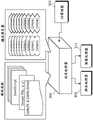
FIG. 4 is a diagram showing the data hierarchy of a BD-ROM.
As shown in fig. 4, on the BD-ROM104 as a disc medium, there are recorded: AV data 103, BD management information 102 such as management information related to AV data and an AV playback sequence (sequence), and a BD playback program 101 that realizes an interactive function.
In the present embodiment, the BD-ROM is described mainly with attention paid to AV applications for reproducing AV contents such as movies, but it is needless to say that the BD-ROM can be used as a recording medium for computer use, such as a CD-ROM or a DVD-ROM.
FIG. 5 shows the structure of logical data recorded on the BD-ROM 104. The BD-ROM104 has a spiral recording area from the inner circumference to the outer circumference, and has a logical address space in which logical data can be recorded between the lead-in of the inner circumference and the lead-out of the outer circumference, as in other optical discs such as DVD and CD.
Further, a special Area called a Burst Cutting Area (BCA) is present inside the lead-in Area, and can be read only by a drive. Since this area cannot be read by an application, it is often used in, for example, copyright protection technology.
In the logical address space, application data such as video data is recorded beginning with file system information (volume). As described in the related art, a file system is a structure for managing data defined by a standard such as UDF or ISO9660, and can read out recorded logical data using a directory or file structure as in a normal PC.
In the case of this embodiment, the directory and file structure on the BD-ROM104 is arranged such that the BDVIDEO directory is positioned at the next level of the ROOT directory (ROOT). The directory is a directory in which data such as AV data and management information (the BD playback program 101, BD management information 102, and AV data 103 shown in fig. 4) handled by the BD-ROM is recorded.
Under the BDVIDEO directory, the following 7 files are recorded.
INFO (fixed file name)
Is one of "BD management information" and is a file in which information relating to the entire BD-ROM is recorded. The BD-ROM player reads out the file first.
PROG (fixed file name)
The "BD playback program" is a file in which programs relating to the entire BD-ROM are recorded.
PL ("XXX" variable, extension "PL" fixed)
Is one of "BD management information", and is a file in which PlayList (PlayList) information, which records a script (scenario), is recorded. Each playlist has a file.
PROG ("XXX" variable, extension "PROG" fixed)
Is one of "BD reproduction programs", and is a file in which the program for each playlist described above is recorded. Correspondence with the playlist is identified by the file body name ("XXX" is consistent).
VOB ('YYY' variable, extension 'VOB' fixed)
Is one of "AV data" and is a file in which VOBs (the same as those described in the conventional example) are recorded. One VOB corresponds to one file.
VOBI ("YYY" variable, extension "VOBI" fixed)
Is one of "BD management information" and is a file in which management information related to VOBs as AV data is recorded. Correspondence with the VOB is identified by the file body name ("YYY" is consistent).
PNG ("ZZZ" variable, extension "PNG" fixed)
Is one of "AV data", and is an image file in the form of PNG (image format standardized by World Wide Web Consortium, W3C) which is image data for constituting subtitles and menu pictures. One PNG image corresponds to one file.
(constitution of Player)
Next, the structure of a player for playing back the BD-ROM104 will be described with reference to FIGS. 6 and 7.
FIG. 6 is a diagram showing an outline of a basic configuration of a BD-ROM player that reproduces the BD-ROM 104.
In the BD-ROM player shown in FIG. 6, data on the BD-ROM104 is read by an optical pickup 202. The read data is recorded in a dedicated memory according to the type of the data.
A BD reproducing program ("bd.prog" or "xxx.prog" file) is recorded in the program recording memory 203, BD management information ("bd.info", "xxx.pl", or "yyy.vobi" file) is recorded in the management information recording memory 204, and AV data ("yyy.vob" or "zzz.png" file) is recorded in the AV recording memory 205.
The BD reproducing program recorded in the program recording memory 203 is processed by the program processing section 206. The BD management information recorded in the management information recording memory 204 is processed by the management information processing section 207.
In addition, the AV data recorded in the AV recording memory 205 is processed by a presentation processing section 208.
The program processing unit 206 receives event information such as information on a playlist to be reproduced and execution timing of a program from the management information processing unit 207, and performs processing of the program. In addition, the playlist to be reproduced can be dynamically changed by a program, and this is realized by transmitting a reproduction command of the changed playlist to the management information processing unit 207.
The program processing unit 206 also receives an event from the user, for example, a request from a remote controller operated by the user, and executes a process for a program corresponding to the user event when the program exists.
The management information processing unit 207 receives an instruction from the program processing unit 206, and analyzes a playlist corresponding to the instruction and management information of a VOB corresponding to the playlist. Further, the presentation processing unit 208 is instructed to reproduce the AV data to be reproduced.
The management information processing unit 207 receives the reference time information from the presentation processing unit 208, and instructs the presentation processing unit 208 to stop the reproduction of the AV data based on the time information. Further, an event indicating the program execution timing is generated for the program processing unit 206.
The presentation processing unit 208 has decoders corresponding to the respective data of video, audio, and subtitle, and decodes and outputs AV data in accordance with an instruction from the management information processing unit 207. The video data and the subtitle data are decoded and rendered on respective dedicated planes (planes).
Specifically, video data is drawn on the video plane 210, and image data such as subtitle data is drawn on the image plane 209. Further, the image composition processing unit 211 performs image composition processing of images drawn on two planes, and outputs the images to a display device such as a TV (television).
As shown in fig. 6, the BD-ROM player adopts a configuration based on the data structure recorded on the BD-ROM104 shown in fig. 4.
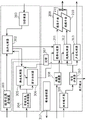
Fig. 7 is a block diagram showing the configuration of the player shown in fig. 6 in detail. The respective components shown in fig. 6 correspond to the respective components shown in fig. 7 as follows.
The AV recording memory 205 corresponds to an image memory 308 and a track buffer (track buffer) 309. The program processing section 206 corresponds to a program processor 302 and a UO (User Operation) manager 303. The management information processing section 207 corresponds to the script processor 305 and the presentation controller 306. The presentation processing section 208 corresponds to a clock 307, a demultiplexer (demultiplexer)310, an image processor 311, a video processor 312, and a sound processor 313.
VOB data (MPEG stream) read out from the BD-ROM104 is recorded in the track buffer 309, and image data (PNG) is recorded in the image memory 308.
The demultiplexer 310 extracts VOB data recorded in the track buffer 309 based on the time obtained from the clock 307. Further, the video data included in the VOB data is sent to the video processor 312, and the audio data is sent to the audio processor 313.
The video processor 312 and the sound processor 313 each include a decoding buffer and a decoder, as prescribed by the MPEG system standard. That is, the video and audio data supplied from the demultiplexer 310 are temporarily stored in the respective decoding buffers, and are decoded by the respective decoders in accordance with the clock 307.
The PNG data recorded in the image memory 308 has the following two processing methods. When the PNG data is data for subtitles, the presentation controller 306 instructs the decoding timing. The script processor 305 temporarily receives time information from the clock 307, and if it is a subtitle display time (start and end), it instructs the presentation controller 306 to display or not display a subtitle so that an appropriate subtitle display can be performed.
The image processor 311, which has received an instruction for decoding/display from the presentation controller 306, extracts the corresponding PNG data from the image memory 308, decodes it, and renders it on the image plane 209.
When the PNG data is data for a menu screen, the program processor 302 instructs the decode timing. When the program processor 302 instructs decoding of the picture is not always decided depending on the BD program being processed by the program processor 302.
As described with reference to fig. 6, the image data and the video data are decoded, drawn on the image plane 209 and the video plane 210, and synthesized and output by the synthesis processing unit 211.
The management information (script, AV management information) read out from the BD-ROM104 is recorded in the management information recording memory 204, but the script information ("bd.info" and "xxx.pl") is read out and processed by the script processor 305. In addition, AV management information ("yyy. vobi") is read out and processed by the presentation controller 306.
The script processor 305 parses information of the playlist, instructs the VOB referred to by the playlist and the reproduction position thereof to the presentation controller 306, and the presentation controller 306 parses management information ("yy. vobi") of the VOB that becomes the target, and issues an instruction to read out the VOB that becomes the target to the drive controller 317.
The drive controller 317 moves the optical pickup 202 in accordance with the instruction of the presentation controller 306, and reads out the AV data to be read. As described above, the read AV data is recorded in the image memory 308 or the track buffer 309.
The script processor 305 monitors the time of the clock 307 and supplies an event to the program processor 302 at a timing set by the management information.
The BD program ("bd.prog" or "xxx.prog") recorded in the program recording memory 203 is subjected to execution processing by the program processor 302. The program processor 302 processes the BD program when an event is transmitted from the script processor 305 or when an event is transmitted from the UO manager 303.
When a request is transmitted from a user via a remote control key, the UO manager 303 generates an event corresponding to the request and transmits the event to the program processor 302.
The BD-ROM is reproduced by the operations of the respective components.
(application space)
FIG. 8 is a diagram showing an application space of a BD-ROM.
In the application space of the BD-ROM, a PlayList (PlayList) becomes a unit of reproduction. The playlist includes a static scenario composed of a playback sequence of the Cell (Cell) and a dynamic scenario described by a program.
The playlist causes only the respective cells to be sequentially reproduced unless there is a dynamic scenario following the program, and the reproduction of the playlist is terminated at a point when the reproduction of all the cells is terminated.
On the other hand, the program can dynamically change the object of reproduction according to the reproduction description of the excess playlist, and/or the user's selection or the state of the player. A typical example is dynamic change of a playback target via a menu screen. In the case of the BD-ROM, the menu is one of functional components for dynamically selecting a playlist, which is a script to be reproduced according to a selection of a user.
The program referred to herein is an event handler (event handler) that is executed using a time event or a user event.
The time event is an event generated based on time information embedded in the playlist. The event transmitted from the script processor 305 to the program processor 302 illustrated in fig. 7 corresponds to this. When the time event is issued, the program processor 302 performs execution processing on the event processing associated by the ID.
As described above, the executed program can instruct reproduction of other play lists, in which case reproduction of the play list currently being reproduced is suspended and shifts to reproduction of the designated play list.
The user event is an event generated by a user's remote controller key operation. User events are broadly divided into two types. The first is an event of menu selection generated by operation of cursor keys ("up", "down", "left" and "right" keys) or "ok" keys provided in the remote controller.
Event processing corresponding to the event of the menu selection is effective only for a limited period within the playlist. That is, as the information of the playlist, the effective period of each event process is set. When the up, down, left, right, or ok key of the remote controller is pressed, the program processor 302 searches for an effective event process, and executes the event process if there is an effective event process. In other cases, the event of the menu selection is ignored.
The second type of user event is an event in which a menu screen generated by operation of the "menu" key is called up (called). When an Event called out from the menu screen is generated, Global Event processing (Global Event Handler) is called out.
The global event processing is not dependent on a playlist, and is always effective event processing. By using this function, a menu call (menu call) of the DVD can be installed. By the install menu call, it is possible to call up a sound or subtitle menu during title reproduction and, after changing the sound or subtitle, to execute title reproduction from the interrupted point.
As a Cell (Cell) constituting a unit of a static scenario in a playlist, all or a part of a playback section of a VOB (MPEG stream) is referred to. The cell has a playback section in the VOB as information of start and end times. VOB management information (VOBI) paired with each VOB has a Time Map (Time Map or TM) in its inside, and the read start address and end address in the VOB (that is, in the target file "yy. Further, details of the time map will be described later using fig. 14.
(details of VOB)
Fig. 9 is a diagram showing the configuration of an MPEG stream (VOB) used in the present embodiment. As shown in FIG. 9, the VOB is composed of a plurality of Video Object units (VOBU). The VOBU is a unit based on a Group Of Pictures (GOP) in an MPEG video stream, and is a unit Of reproduction Of a multiplexed stream also containing audio data.
The VOBU has a reproduction time of 0.4 to 1.0 second, and generally has a reproduction time of 0.5 second. This is derived by the structure of the MPEG GOP, typically 15 frames per second (NTSC case).
The VOBU has a video pack (V _ PCK) as video data and an audio pack (a _ PCK) as audio data inside it. Each packet is composed of 1 sector, and in the present embodiment, each packet is composed of 2kB units.
Fig. 10 is a diagram showing a structure of a packet in an MPEG stream.
As shown in fig. 10, basic data such as video data and audio data are sequentially written into a data storage area of a data packet (packet) called a payload (payload) from the beginning. A data packet header (packet header) is given to the payload to constitute one data packet.
A packet header (packet header) records an ID (stream _ ID) for identifying which stream data, video data, or audio data, and which stream data is stored in the payload, and when there is a plurality of streams corresponding to each of the video data and the audio data, a Decoding Time Stamp (DTS) and a Presentation Time Stamp (PTS) which are Time stamps of decoding and display Time information of the payload.
The DTS and PTS do not necessarily have to be recorded in the entire data packet header, and the rules for recording are specified according to MPEG. The details of the rules are not described in the MPEG System (ISO/IEC13818-1) Standard, and are therefore omitted.
A packet is also formed by assigning a packet header (pack head) to the data packet. In the header of the data packet, a System Clock Reference (SCR) is recorded, which is a time stamp indicating when the packet of data passes through the demultiplexer 310 and is input to a decoding buffer of each elementary stream.
(interleaved recording of VOB)
The interleaved recording of VOB files will be described using fig. 11 and 12.
FIG. 11 is a diagram for explaining the relationship between AV data and the structure of a BD-ROM player.
The upper part of fig. 11 is a part of the player configuration described above with reference to fig. 7. As shown in the figure, data on the BD-ROM is input to the track buffer 309 via the optical pickup 202 if it is a VOB, i.e., MPEG stream, and to the image memory 308 if it is a PNG, i.e., image data.
The track buffer 309 is a First-In First-Out (FIFO) buffer, and data of the input VOB is transmitted to the demultiplexer 310 In the order of input. At this time, according to the SCR described above, each packet is extracted from the track buffer 309 and sent to the video processor 312 or the sound processor 313 via the demultiplexer 310.
On the other hand, in the case of image data, which image is drawn is instructed by the presentation controller 306 (refer to fig. 7). In addition, the image data already used for drawing is simultaneously deleted from the image memory 308 in the case of the subtitle image data, and is still retained in the image memory 308 in the case of the menu image data.
This is because the drawing of the menu may depend on the user operation, and thus the same image may be drawn a plurality of times.
The lower diagram of FIG. 11 shows interleaved (interleave) recording of the VOB file and the PNG file on the BD-ROM.
Generally, in the case of a ROM, such as a CD-ROM or DVD-ROM, AV data is recorded continuously as a series of continuous playback units. As long as recording is continued, the drive only has to read out data sequentially and send it to the player side.
However, when AV data to be continuously reproduced is cut and discretely arranged on a disc, seek operation is inserted between each continuous section, and data reading is stopped during this period. That is, the supply of data may be stopped.
The same is true for the case of BD-ROM, and it is desirable that the VOB file be recorded in a continuous area, but there is data that is reproduced in synchronization with video data recorded in the VOB, such as subtitle data, and it is necessary to read out the subtitle data from the BD-ROM by some method, as in the case of the VOB file.
As one of methods for reading subtitle data, there is a method of collectively reading out image data for subtitles (PNG file) before the start of reproduction of VOBs. However, in this case, a large amount of memory for temporary recording is required, which is unrealistic.
Therefore, in the present embodiment, a method is used in which the VOB file is divided into several blocks (blocks) and the VOB file and the image data are recorded in an interleaved manner.
The lower part of fig. 11 is a diagram for explaining the interleaved recording. By appropriately interleaving VOB files and image data, it is possible to store the image data in the image memory 308 at a necessary timing without requiring a large amount of temporary recording memory as described above.
However, it is needless to say that reading of VOB data is stopped when reading out image data.
Fig. 12 is a diagram for explaining a VOB data continuous supply model using the track buffer 309 for solving the problem in the above-described interleaved recording.
As already described, data of the VOB is temporarily stored in the track buffer 309. When the data input rate to the track buffer 309 is set higher than the data output rate from the track buffer 309, the data storage amount of the track buffer 309 increases as long as data is continuously read out from the BD-ROM.
Here, the input rate to the track buffer 309 is Va, and the output rate from the track buffer 309 is Vb. As shown in the upper diagram of fig. 12, one continuous recording area of the VOB is set to continue from the logical address "a 1" to "a 2". Further, the sections where the image data is recorded between "a 2" and "a 3" are sections where the VOB data cannot be read out.
The lower diagram of fig. 12 shows the storage amount of the track buffer 309. The horizontal axis represents time, and the vertical axis represents the amount of data stored inside the track buffer 309. The time "t 1" indicates the time at which the readout of "a 1" is started, and "a 1" is the starting point (starting point) of one continuous recording area of the VOB.
After this time, the data is stored in the track buffer 309 at a rate Va-Vb. Needless to say, the rate is the difference between the input and output rates of the track buffer 309. The time "t 2" is the time when the data of "a 2" is read, and "a 2" is the end point (end point) of one continuous recording area.
That is, the amount of data in the track buffer 309 increases at the rate Va-Vb between times "t 1" and "t 2", and the data storage amount B (t2) at time "t 2" can be obtained by the following expression 1.
B (t2) ═ (Va-Vb) × (t2-t1) (formula 1)
Thereafter, since the image data continues until the address "a 3" on the BD-ROM, the input to the track buffer 309 becomes 0, and the amount of data in the track buffer 309 decreases at the output rate "-Vb". This decrease in the amount of data continues until the readout position "a 3", that is, until "t 3" in time.
Here, it is important: when the amount of data stored in the track buffer 309 becomes 0 before the time "t 3", the data of the VOB supplied to the decoder is lost, and the reproduction of the VOB is stopped.
However, in the case where data remains in the track buffer 309 at time "t 3", it means that the reproduction of the VOB is continuously performed without being stopped.
The conditions for continuously performing the reproduction of the VOB without stopping the reproduction can be expressed by the following (equation 2).
B (t2) ≥ Vb × (t3-t2) (formula 2)
That is, the arrangement of the image data may be determined so as to satisfy (expression 2).
(guide data Structure)
The structure of the boot data (BD management information) recorded in the BD-ROM will be described with reference to fig. 13 to 19.
Fig. 13 is a diagram showing the internal structure of a VOB management information file ("yyy.
The VOB management information has stream Attribute information (Attribute) and a Time Map (TMAP) of the VOB. The stream attribute information is configured to have each of Video attributes (Video) and Audio attributes (Audio # 0 to Audio # m). Particularly in the case of audio streams, since a VOB can simultaneously have a plurality of audio streams, the Number of data fields (data fields) of an audio attribute can be determined according to the Number (Number) of audio streams.
The following are examples of fields and respective desirable values that a Video attribute (Video) has.
Compression method (Coding):
MPEG1
MPEG2
MPEG4
resolution (Resolution):
1920×1080
1280×720
720×480
720×565
aspect ratio (Aspect):
4:3
16:9
frame rate (Framerate):
60
59.94
50
30
29.97
25
24
described below are examples of fields and respective desirable values that an Audio attribute (Audio) has.
Compression method (Coding):
AC3
MPEG1
MPEG2
LPCM
number of channels (Ch):
1~8
language attribute (Language):
JPN、ENG、…
the Time Map (TMAP) is a table having information of each VOBU, and has: the VOB has the VOBU Number (Number) and VOBU information (VOBU # 1 to VOBU # n).
Each VOBU information has: the reproduction time length (Duration) of the VOBU and the data Size (Size) of the VOBU.
Fig. 14 is a diagram for explaining details of VOBU information.
As is well known, an MPEG stream has: the aspect as time and the aspect as data size are both aspects with respect to physical quantities. For example, since Audio Code 3(Audio Code number 3: AC3), which is a standard for compression of Audio, performs compression at a fixed bit rate, the relationship between time and address can be obtained by a linear equation.
However, in the case of MPEG video data, each frame (frame) has a fixed display time, for example, in the case of NTSC, 1 frame has a display time of 1/29.97 seconds, but the compressed data size of each frame varies greatly depending on the characteristics of the picture, the type of picture used in compression, so-called I/P/B picture.
Therefore, in the case of MPEG video, the relationship between time and address cannot be expressed in the form of a general expression.
Of course, it is impossible to express time and data in the form of a general expression in VOBs that are MPEG streams obtained by multiplexing MPEG video data.
Instead, combining the relationship of time and address within the VOB is a Time Map (TMAP). As shown in fig. 14, a table having the number of frames in the VOBU and the number of packets in the VOBU as entries (entries) for each VOBU is a Time Map (TMAP).
A method of using the Time Map (TMAP) will be described with reference to fig. 15.
Fig. 15 is a diagram for explaining an address information acquisition method using time mapping.
As shown in fig. 15, in the case where Time information (Time) is provided, first, to which VOBU the Time belongs is retrieved. Specifically, the number of frames per VOBU of the time map is added, and a VOBU having a sum of the number of frames exceeding a value obtained by converting the time into the number of frames or coinciding with the value obtained by converting the time into the number of frames becomes a VOBU corresponding to the time.
Next, the size of each VOBU of the time map is added up to the VOBU immediately before the VOBU, and this value becomes the start Address (Address) of the pack to be read out to reproduce the frame including the supplied time.
In this way, an address corresponding to the supplied time information can be obtained in the MPEG stream.
Next, the internal structure of the playlist ("xxx.pl") will be described with reference to fig. 16.
Fig. 16 is a diagram showing the structure of a playlist.
The play list is composed of a cell list (CellList) and an event list (EventList).
The cell list (CellList) is information indicating a sequence of playback cells in a playlist, and the cells are played back in the order described in the playlist.
The contents of the Cell list (CellList) are the Number of cells (Number) and the respective Cell information (Cell # 1 to Cell # n).
Each Cell information (Cell # -Cell # n) has a VOB file name (VOBName), a valid section start time (In) and a valid section end time (Out) In the VOB, and a subtitle table (subtitle table).
The valid section start time (In) and the valid section end time (Out) are expressed by the frame number In the VOB, and the address of VOB data necessary for reproduction can be obtained by using the Time Map (TMAP).
A subtitle table (subtitle table) is a table having subtitle information reproduced in synchronization with the VOB. Similarly to sound, a subtitle can have a plurality of languages, and the subtitle table (subtitle table) includes the Number of languages (Number) and tables (Language # 1 to Language # k) of the respective languages following the Number of languages.
The Language tables (Language # 1 to Language # k) include Language information (Language), the Number of subtitles (Number) of displayed subtitles, and subtitle information (Speech # 1 to Speech # j) of displayed subtitles, and each subtitle information (Speech # 1 to Speech # j) includes a corresponding image data file Name (Name), a subtitle display start time (In), a subtitle display end time (Out), and a subtitle display Position (Position).
The event list (EventList) is a table that defines events that occur within the playlist. The Event list includes the Number of events (Number) and the events (Event # 1 to Event # m) following the Number of events, and each of the events (Event # 1 to Event # m) includes the Type (Type) of the Event, the id (id) of the Event, the Event generation Time (Time), and the validity period (Duration).
Fig. 17 is a diagram showing a configuration of an event processing table ("xxx. prog") having event processing (a time event and a user event for menu selection) for each playlist.
The event processing table has a defined Number of event processes/programs (Number) and individual event processes/programs (Program # 1 to Program # n).
The description in each event handler/Program (Program # 1 to Program # n) has a definition of event handler start (< event _ handler > tag) and an ID of event handler paired with the ID of the event (event _ handler ID), and the Program is described between brackets "{" and "}" immediately after "function".
Next, the internal structure of the information ("bd.info") related to the entire BD-ROM will be described with reference to fig. 18.
Fig. 18 is a diagram showing the configuration of BD-info, which is the entire BD-ROM information.
The BD-ROM global information includes a title list (TitleList) and an event list (EventList) for global events.
The Title list (Title list) includes the Number of titles (Number) in the disc and the respective Title information (Title # 1 to Title # n) next to the Number of titles.
Each Title information (Title # 1 to Title # n) includes: a table of playlists (PLTalble) contained in the title and a chapter list (ChapterList) within the title. The table of playlists (PLTable) has the Number of playlists within a title (Number) and a playlist Name (Name), i.e., a file Name of a playlist.
The Chapter list (Chapter list) includes the Number of chapters (Number) included in the title and each Chapter information (Chapter # 1 to Chapter # n), each Chapter information (Chapter # 1 to Chapter # n) has a table (CellTable) of cells included in the Chapter, and the table (CellTable) of cells includes the Number of cells (Number) and entry information (CellEntry # 1 to CellEntry # k) of each cell.
Entry information (CellEntry # 1 to CellEntry # k) of a cell is described by a playlist name including the cell and a cell number in the playlist.
The Event list (EventList) has the Number (Number) of global events and information (Event # 1 to Event # m) of each global Event. It should be noted herein that the first defined global event is referred to as a first event (FirstEvent), which is the first event to be executed when the BD-ROM is inserted into the player.
The information of each global Event (Event # 1 to Event # m) includes only an Event Type (Type) and an id (id) of the Event.
Fig. 19 is a diagram showing the structure of a global event processing table ("bd. The contents of this table are the same as those of the event processing table described in fig. 17, and the description thereof is omitted.
(mechanism for event occurrence)
The mechanism of event occurrence will be described with reference to fig. 20 to 22.
Fig. 20 is a diagram showing an example of a time event.
Pl, a temporal event is defined by an event list (EventList) of a play list ("xxx).
When the event Type (Type) is "TimeEvent", which is an event defined as a temporal event, the script processor 305 outputs a temporal event having an ID "Ex 1" to the program processor 302 at a time when the event generation time ("t 1") is reached.
The program processor 302 searches for an event process having an event ID "Ex 1" and performs an execution process on the event process as an object. For example, in the case of the present embodiment, it is possible to perform drawing of two button images and the like.
Fig. 21 is a diagram showing an example of a user event by a menu operation by the user.
As described above, the user event based on the menu operation is also defined by the event list (EventList) of the play list ("xxx.
When the event Type (Type) defined as the user event is "userrevent", the user event becomes ready (ready) at the time when the event generation time ("t 1") is reached. At this time, the event itself has not been generated.
This event is in the ready state during a period ("T1") described in the effective specification information (Duration).
As shown in fig. 21, when a user presses one of the "up", "down", "left" and "right" keys of the remote controller key or the "ok" key, first, the UO manager 303 generates a UO event and outputs the UO event to the program processor 302.
The program processor 302 streams the UO event to the script processor 305, and the script processor 305 retrieves whether there is a valid user event at the time when the UO event is received.
When the result of the search indicates that there is a target user event, the script processor 305 generates a user event and outputs the user event to the program processor 302.
The program processor 302 searches for an event process having an event ID, for example, "Ev 1" in the case of the example shown in fig. 21, and executes the process for the target event process. In the case of this example, reproduction of playlist # 2 is started.
The generated user event does not include information on which remote control key is pressed by the user. The information of the selected remote controller key is transferred to the program processor 302 through the UO event and recorded and held in a register provided in the virtual player.
The program of event processing can check the value of the register and perform branch processing.
Fig. 22 is a diagram showing an example of a global event.
As described above, the global event is defined by an event list (EventList) of BD-ROM global information ("BD.
An event defined as a global event, that is, an event whose event Type (Type) is "globaleevent" is generated only when the user has performed a remote controller key operation.
When a menu key is pressed by the user, first, a UO event is generated by the UO manager 303 and output to the program processor 302. Program processor 302 streams the UO event to script processor 305.
The script processor 305 generates a corresponding global event and sends it to the program processor 302. The program processor 302 searches for an event process having the event ID "menu" and executes the event process as an object. For example, in the case of the example shown in fig. 22, reproduction of playlist # 3 is started.
In the present embodiment, only the menu key is referred to, but a plurality of menu keys may be provided as in a remote controller of a player for playing a DVD. By defining the ID corresponding to each menu key, appropriate processing corresponding to each menu key can be performed.
(virtual player)
Fig. 23 is a diagram for explaining a functional configuration of the program processor 302.
The functional configuration of the program processor 302 will be described with reference to fig. 23.
The program processor 302 is a processing module having a virtual player inside. The virtual player is a functional model defined for the BD-ROM, and does not depend on the actual installation of each BD-ROM player. That is, it is ensured that the same function can be performed regardless of which type of BD-ROM player.
The virtual player has roughly two functions. Programming functions and player variables. Player variables are stored and held in registers.
The programming function is based on Java (registered trademark) Script, and three functions described below are defined as BD-ROM specific functions.
The link function: the current reproduction is stopped and the reproduction from the specified play list, unit, time is started.
Link(PL#,Cell#,time)
PL #: play list name
Cell #: cell number
time: reproduction start time in cell
PNG depicts the function: rendering specified PNG data on the image plane 209
Draw(File,X,Y)
File: PNG filename
X: position of X coordinate
Y: y coordinate position
Image plane cleaning function: clearing designated areas of the image plane 209
Clear(X,Y,W,H)
X: x coordinate position
Y: y coordinate position
W: width in X direction
H: width in Y direction
In addition, the player variables are: system Parameters (SPRMs) indicating the setting values of the player and the like, and general purpose parameters (GPRMs) that can be used for general purposes.
Fig. 24 is a diagram showing a list of System Parameters (SPRMs).
SPRM (0): language code
SPRM (1): audio stream sequence number
SPRM (2): subtitle stream sequence number
SPRM (3): number of angles
SPRM (4): title serial number
SPRM (5): chapter number
SPRM (6): program sequence number
SPRM (7): unit number
SPRM (8): selection key information
SPRM (9): guiding timer
SPRM (10): reproducing time information
SPRM (11): mixing mode for karaoke
SPRM (12): country information for restriction
SPRM (13): level of restriction
SPRM (14): player setting (video)
SPRM (15): player setting (Audio)
SPRM (16): language code for audio streaming
SPRM (17): language code for sound stream (expansion)
SPRM (18): language code for caption stream
SPRM (19): language code for caption stream (expansion)
SPRM (20): player area code
SPRM (21): reservation
SPRM (22): reservation
SPRM (23): reproducing the state
SPRM (24): reservation
SPRM (25): reservation
SPRM (26): reservation
SPRM (27): reservation
SPRM (28): reservation
SPRM (29): reservation
SPRM (30): reservation
SPRM (31): reservation
In the present embodiment, the programming function of the virtual player is a function based on Java (registered trademark) Script, but other programming functions such as B-Shell and PerlScript used in UNIX (registered trademark) OS and the like may be used instead of Java (registered trademark) Script. In other words, the program language in the present disclosure is not limited to Java (registered trademark) Script.
(example of the program)
Fig. 25 and 26 are diagrams showing examples of the event processing routine.
Fig. 25 is a diagram showing an example of a program of event processing relating to control of a menu screen having two selection buttons.
At the head of the Cell (PlayList #1.Cell #1), the program on the left side of fig. 25 is executed using the time event. Here, "1" is set in GPRM (0), which is one of the general parameters, first. GPRM (0) is used in the program to identify the selected button. In the initial state, the button [1] arranged on the left side has a selected state as an initial value.
Next, the PNG is drawn for each of the button [1] and the button [2] using "Draw" which is a drawing function. The button [1] draws the PNG image "1 black. The button [2] draws the PNG image "2 white.
In addition, at the end of this section, the program on the right side of fig. 25 is executed using the time event. Here, the Link function is used to specify reproduction again from the beginning of the cell.
Fig. 26 is a diagram showing an example of a procedure of event processing relating to a user event of menu selection.
In the event processing, programs corresponding to the cases where any one of the remote control keys of the "left" key, the "right" key, and the "decision" key is pressed are written. When the user presses a remote control key, a user event is generated as described with reference to fig. 21, and the event processing of fig. 26 is started.
In this event processing, branch processing is performed as follows using the value of GPRM (0) identifying the selected button and SPRM (8) identifying the selected remote controller key.
Condition 1) case where button [1] has been selected and the selection key is the "Right" key
GPRM (0) is reset to 2, and the button in the selected state is changed to the right button [2 ].
The images of the button [1] and the button [2] are rewritten.
Condition 2) case where the selection key is "OK" and the button [1] has been selected
Reproduction of playlist # 2 is started.
Condition 3) case where the selection key is "OK" and the button [2] has been selected
Reproduction of playlist # 3 is started.
The routine shown in fig. 26 is explained and executed in the above-described manner.
(Player processing flow)
The flow of processing in the player will be described with reference to fig. 27 to 30.
FIG. 27 is a flowchart showing the flow of basic processing for AV data playback in a BD-ROM player.
When the BD-ROM is inserted (S101), the BD-ROM player performs reading and parsing of "bd.info" (S102) and reading of "bd.prog" (S103). Info and prog are temporarily stored together in the management information recording memory 204 and are parsed by the script processor 305.
Next, the script processor 305 generates a first event (FirstEvent) according to the first event information in the "bd. The generated first event is received by the program processor 302, and the execution process is performed on the event process corresponding to the event (S105).
It is expected that information specifying a playlist to be reproduced first is recorded in the event processing corresponding to the first event. If the playlist reproduction is not instructed, the player continues to wait for the reception of the user event (no in S201) without any reproduction.
When a remote control operation from a user is accepted (yes in S201), the UO manager 303 generates a UO event to the program processor 302 (S202).
The program processor 302 determines whether or not the UO event is an event by a menu key (S203), and if the UO event is a menu key (yes in S203), the UO event is caused to flow to the script processor 305, and the script processor 305 generates a user event (S204). The program processor 302 performs an execution process on an event process corresponding to the generated user event (S205).
FIG. 28 is a flowchart showing the flow of processing from the start of play list reproduction to the end of VOB reproduction in a BD-ROM player.
As described above, play list reproduction is started with the first event process or the global event process (S301). The script processor 305 reads and analyzes the playlist "xxx. pl" (S302) and reads the program information "xxx. prog" corresponding to the playlist (S303), as information necessary for reproducing the playlist to be reproduced.
Next, the script processor 305 starts reproduction of the unit based on the unit information registered in the play list (S304). The unit reproduction refers to a case where the presentation controller 306 starts AV data reproduction from the scenario processor issuing a request to the presentation controller 306 (S305).
When the reproduction of AV data is started, the presentation controller 306 reads in (S402) and parses the information file "xxx. The presentation controller 306 determines the VOBU at which reproduction starts and the address thereof using the time map and instructs the drive controller 317 to read out the address. The drive controller 317 reads out VOB data "yyy.
The read VOB data is sent to the decoder and reproduction is started (S404). VOB reproduction is continued until the reproduction section of the VOB is completed (S405), and when the reproduction section is completed, if the next cell exists (yes in S406), the process proceeds to reproduction of the cell (S304). If there is no next cell (no in S406), the processing related to playback ends.
Fig. 29 is a flowchart showing the flow of event processing after the start of AV data reproduction.
FIG. 29A is a flowchart showing the flow of processing relating to a time event in the BD-ROM player.
In addition, the BD-ROM player is an event-driven type player model. When playback of a playlist is started, event processing procedures of a time event system, a user event system, and a subtitle display system are started, respectively, and event processing is executed in parallel.
When the reproduction of the playlist is started in the BD-ROM player (S501), it is confirmed that the reproduction of the playlist is not completed (no in S502), and the script processor 305 confirms whether or not the time event occurrence time is reached (S503).
When the time event occurrence time is reached (yes in S503), the script processor 305 generates a time event (S504). The program processor 302 receives the time event and performs an execution process on the event process (S505).
When the time event occurrence time is not reached (no in S503) and when the execution process of the event process is completed, the process after the completion confirmation (S502) of the playlist reproduction is repeated.
In addition, when the end of the play list reproduction is confirmed (yes in S502), the process of the time event system forcibly ends.
FIG. 29(B) is a flowchart showing the flow of processing relating to a user event of the BD-ROM player.
When the playback of the playlist is started in the BD-ROM player (S601), the UO manager 303 checks that the playback of the playlist has not ended (no in S602), and checks whether or not there is acceptance of the UO.
When a UO is accepted (yes in S603), the UO manager 303 generates a UO event (S604). Program processor 302 receives the UO event and confirms whether the UO event is a menu call (call out).
If the call is a menu call (yes in S605), the program processor 302 causes the script processor 305 to generate an event (S607), and the program processor 302 performs an execution process on the event process (S608).
If it is determined that the UO event is not a menu call (no in S605), this indicates that the UO event is an event caused by a cursor key or an "ok" key. In this case, the script processor 305 determines whether or not the current time is within the user event validity period, and if the current time is within the validity period (yes in S606), the script processor 305 generates a user event (S607), and the program processor 302 executes an event process to be processed (S608).
Further, when no UO is accepted (no in S603), when the current time is not within the user event validity period (no in S606), and when the execution process of the event process is finished, the process after the completion confirmation (S602) of the playlist reproduction is repeated.
In addition, when it is confirmed that the play list reproduction is ended (yes in S602), the process of the user event system is forcibly ended.
Fig. 30 is a flowchart showing the flow of processing of subtitle data in a BD-ROM player.
When the playback of the playlist is started in the BD-ROM player, it is confirmed that the playback of the playlist has not ended (no in S702), and the script processor 305 confirms whether or not the subtitle display start time is reached. When the subtitle display start time is reached (yes in S703), the script processor 305 instructs the presentation controller 306 to perform subtitle drawing, and the presentation controller 306 instructs the image processor 311 to perform subtitle drawing. In accordance with the instruction, the image processor 311 draws a subtitle on the image plane 209 (S704).
When the subtitle display start time is not reached (no in S703), it is checked whether or not the subtitle display end time is reached. When it is determined that the time is the subtitle display end time (yes in S705), the presentation controller 306 instructs the image processor 311 to clear subtitles.
The image processor 311 clears the drawn subtitle from the image plane 209 in accordance with the instruction (S706).
Further, when the subtitle rendering by the image processor 311 is finished (S704), when the subtitle clearing by the image processor 311 is finished (S706), and when it is determined that the time is not the subtitle display end time (no in S705), the processing after the end confirmation of the playlist reproduction (S702) is repeated.
In addition, when it is confirmed that the play list reproduction is ended (yes in S702), the process of the subtitle display system is forcibly ended.
Through the above operation, the BD-ROM player performs basic processing related to the playback of the BD-ROM based on a user instruction, BD management information recorded on the BD-ROM, and the like.
(embodiment mode 2)
Next, embodiment 2 of the present disclosure will be described.
Fig. 31 is a diagram illustrating a method of transmitting high-luminance metadata by using a video coding scheme such as MPEG-4AVC (alias h.264) or HEVC (alias h.265). Here, a unit having a picture reference structure equivalent to a GOP (Group Of Pictures) used for improving random access in MPEG-2Video is grouped into a plurality Of Pictures and encoded as a GOP in MPEG-4AVC or HEVC.
Fig. 31(a) shows the coding order of a plurality of NAL units in a first access unit (GOP) picture. In a picture at the beginning of a GOP, NAL units of 1 AU delimiter (AU delimiter), 1 SPS, 1 or more PPS, 0 or more SEI messages (SEI message), 1 or more slices (Slice) constituting the picture are continued, followed by NAL units of padding data (Filler data), sequence End (End of sequence), and stream End (End of stream), as necessary.
In the SEI messages (SEI)(s), following the Buffering period SEI message (Buffering period SEI message), several other SEI messages (SEI messages) follow as necessary. For example, (1) unregistered User data SEI message (GOP) indicating the reference relationship of pictures in the GOP, (2) unregistered User data SEI message (CC) holding Closed caption (Closed caption) information of the picture, (3) unregistered User data message (HDRb) containing basic and static high luminance metadata indicating the luminance range such as the maximum luminance or the minimum luminance in all the pictures in the video sequence (VOB), (4) as indicating the luminance range such as the maximum luminance or the minimum luminance in all the pictures in the picture or GOP, several SEI messages, such as a User data unregistered SEI message (HDRe) containing more detailed and dynamic high-luminance metadata than the SEI message (HDRb), are encoded in this order.
The aforementioned SEI message (HDRb) or SEI message (HDRe) is transmitted together with the video information. This is because luminance-related information used in mastering (masking) is transmitted, and the luminance value (Y) of each pixel obtained after decoding video information is given to the extent to which the luminance value (cd/m) actually corresponds2) And so on.
For example, as a result of decoding a video, the luminance at the time of mastering of a pixel having a luminance value (Y) of 1000 is 5000cd/m2Information on the relationship between the luminance of the pixel and the luminance at the time of the mastering process is included in the SEI message (HDRb) or the SEI message (HDRe). In addition, the maximum brightness (cd/m) that can be expressed by the TV connected to the player is obtained2) In the case of (2), information for changing the dynamic range of the luminance direction of the entire screen is held in the SEI message (HDRb) or the SEI message (HDRe).
The SEI message (HDRb) is an SEI message transmitted in units of pictures or GOPs to indicate that the video sequence is an HDR video sequence, and transmits information on the static luminance of the entire video sequence (VOB). The HDR video sequence referred to herein is a video sequence in which SEI message (HDRb) is recorded.
SEI message (HDRe) that conveys information about more detailed and dynamic luminance need not be recorded in the HDR video sequence, and may not exist in 1 in the HDR video sequence. In addition, when the SEI message (HDRe) exists, the SEI message needs to be encoded immediately after the SEI message (HDRb), and luminance-related information is transmitted in units of pictures or GOPs.
Fig. 31(b) shows the coding order of a plurality of NAL units in a picture (non-first access unit) other than the picture at the beginning of the GOP. In a non-GOP-headed picture, NAL units of 1 AU delimiter (AU delimiter), 0 or 1 PPS, 0 or more SEI messages, and 1 or more slices constituting the picture are consecutive. Further, each NAL unit of padding data (Filler data), sequence End (End of sequence), and stream End (End of stream) follows thereafter as necessary.
The SEI message (HDRb) or SEI message (HDRe) stores the above information, and is given on a screen-by-screen basis in the method shown in fig. 31. When luminance-related information is transmitted in GOP units, both SEI message (HDRb) and SEI message (HDRe) are assigned only to the top pictures of GOPs, and nothing is assigned to the non-top pictures of GOPs.
Fig. 32 is a diagram illustrating a method of multiplexing HDR video streams including SEI message (HDRe) by MPEG-2 TS. In this embodiment, the sequence may be the same as the flow or may be a part of the flow. A 1-picture (1 frame or 1 video access unit) is stored in a 1PES packet, and after the HDR video stream is PES-converted, the data in the PES packet is divided and stored in order in the payload of each TS packet with PID X.
In the case of the method shown in fig. 32, among TS packets having the same PID (PID ═ X), a PES packet having a stream _ id of 0 × E1 is divided into HDR video sequences each of which is included in an SEI message (HDRe) and stored in order. Further, when the HDR video sequence is output in HDMI (registered trademark), as in the method shown in fig. 32, when information of SEI message (HDRe) is transmitted, processing for retrieving SEI message (HDRe) from the entire video sequence sometimes becomes dull.
Fig. 33 is a diagram of another method of multiplexing HDR video streams included in SEI message (HDRe) by MPEG-2 TS. 1 picture (1 frame or 1 video access unit) is stored in 1PES packet, and after the HDR video stream is PES-converted, in the payload of each TS packet with PID X and Z, the data in the PES packet is divided and stored in order.
In the case of the method shown in fig. 33, among TS packets whose PID is X, an HDR video sequence is stored as a PES packet whose stream _ id is 0 × E1, and only an SEI message (HDRe) is stored in the TS packet whose PID is Z. When outputting an HDR video with HDMI (registered trademark), when information of SEI message (HDRe) is transmitted, only SEI message (HDRe) is stored in TS packets whose PID is Z, as in the method shown in fig. 33. Therefore, processing for retrieving SEI message (HDRe) is easy.
It is simple to decode only HDR video sequences that are transported in TS packets with PID ═ X. However, in order to reproduce a video with higher luminance including SEI message (HDRe), additional processing is required to transfer TS packets with PID X and PID Z to the same TB buffer (pre-stage buffer used in the T-STD model of the MPEG-2 System).
Fig. 34 is a diagram for explaining another method of multiplexing HDR video streams up to SEI message (HDRe) by MPEG-2 TS. A video stream is PES-formed by dividing 1 picture (1 frame or 1 video access unit) and storing it in each of 3 PES packets. Thereafter, each of the 3 PES packets is divided as necessary and stored in the payload of each TS packet with PID ═ X in order.
In the case of the method shown in fig. 34, among TS packets whose PID is X, an HDR video sequence is stored as 2 PES packets whose stream _ id is 0 × E1. Furthermore, only SEI message (HDRe) is stored separately in TS packets having the same PID ═ X as PES packets having the same stream _ id ═ 0 × E1 and PES _ priority ═ 0.
When outputting HDR video with HDMI (registered trademark), as in the method shown in fig. 34, when information of SEI message (HDRe) is transmitted, PES packets whose stream _ id is 0 × E1 and PES _ priority is 0 are retrieved from each TS packet whose PID is X. Therefore, the process for retrieving the SEI message (HDRe) is not as easy as the method shown in fig. 33.
However, there is no great difference in decoding only the HDR video sequence transmitted in TS packets with PID ═ X, and there is no great difference in decoding not only the HDR video sequence but also SEI message (HDRe), and the method shown in fig. 34 can be realized.
The PES _ priority value does not necessarily have to be the combination, and similar effects can be obtained by setting PES _ priority to 1 for PES packets in which SEI message (HDRe) is stored.
Fig. 35 is a diagram for explaining another method of multiplexing HDR video streams up to SEI message (HDRe) by MPEG-2 TS. The method shown in fig. 35 is different from the method shown in fig. 34 in that the transport _ priority of a TS packet storing PES packets including SEI message (HDRe) is 0.
When outputting HDR video with HDMI (registered trademark), when information of SEI message (HDRe) is transmitted, SEI message (HDRe) is analyzed from TS packets with PID X and transport _ priority 0 as in the method shown in fig. 35. Therefore, the amount of processing for retrieving the SEI message (HDRe) is almost as easy as the method shown in fig. 33, and the method shown in fig. 35 can be realized.
In this case, there is no difference in decoding only the HDR video sequence, and there is no difference in decoding not only the HDR video sequence but also the SEI message (HDRe) on the T-STD model, and the method shown in fig. 35 can be realized. For example, a PID signal separator (demultiplexer) of the TS decoder also separates streams based on the value of transport _ priority. Thus, a decoder that uses information up to the SEI message (HDRb) to increase luminance without responding to the SEI message (HDRe) can easily discard TS packets including the SEI message (HDRe) by the PID demultiplexer.
The value of transport _ priority may not necessarily be the combination, and a similar effect can be achieved by setting the transport _ priority to 1 for a TS packet storing SEI message (HDRe).
Fig. 36 is a diagram for explaining another method of multiplexing HDR video streams up to SEI message (HDRe) by MPEG-2 TS. In the method shown in fig. 36, PES packets are configured as in the method shown in fig. 34 or fig. 35 using two types of PIDs as in the method shown in fig. 33. The method shown in fig. 36 has the same advantages and disadvantages as the method shown in fig. 33.
Fig. 37 is a diagram for explaining another method of multiplexing HDR video streams up to SEI message (HDRe) by MPEG-2 TS. In the method shown in fig. 37, SEI message (HDRe) is stored in a PES packet having PES _ priority of 0, which is a different PES packet from the PES packet in which SEI message (HDRb) and the like are stored. After the slice NAL unit is finished, PES packets with PES _ priority of 0 are multiplexed into TS packets with PID of Z, which is different from TS packets with PID of X. The multiplexing position of the SEI message (HDRe) immediately follows the picture data. Therefore, in the method shown in fig. 37, the HDR video sequence up to the SEI message (HDRb) is stored in 1PES packet. Apart from this, the method shown in fig. 37 has the same advantages and disadvantages as the method shown in fig. 33 in common.
Fig. 38 is a diagram for explaining a method of multiplexing an extended video sequence, which is a video sequence different from the HDR video sequence, with MPEG-2TS in place of SEI message (HDRe). In the method shown in fig. 38, instead of transmitting high luminance extended metadata with SEI message (HDRe), an extended video sequence (enhanced layer video sequence) is transmitted as extended video information with respect to a HDR video sequence (Base layer video sequence with user data associated SEI message (HDRb)).
For example, an Enhancement frame PES # n extended picture included in the extended video sequence is added to a Base picture of the Base frame PES # n included in the HDR video sequence. This enables high luminance extension of the HDR video sequence to be performed more accurately using more data than the SEI message. Here, the corresponding pictures may be made to have the same PTS with each other, indicating the correlation between the pictures. For example, a correlation indicating "PTS # b1 of a base picture" to "PTS # e1 of an extended picture" is shown.
The above-described base video sequence and extended video sequence are multiplexed into MPEG-2TS as completely different 2video sequences, respectively, with PES packets having different PIDs.
In the PMT packet, in order to correctly specify a pair of a base video sequence and an extended video sequence, the pair may be expressed using descriptor (). For example, in the method shown in fig. 38, HDR _ pairing _ descriptor () is described in a PMT packet. The HDR _ pairing _ descriptor () contains the number of pairs (number _ of _ HDR _ pairs) in the MPEG-2TS and PID values used for the base video sequence and the extended video sequence for each pair. The PID value used by the base video sequence is denoted by base _ layer _ video _ sequence _ PID, and the PID value used by the extended video sequence is denoted by enhancement _ layer _ video _ sequence _ PID. By describing such HDR _ pairing _ descriptor (), an accurate combination of pairs can be represented.
Fig. 39 shows a structure of a subtitle video stream constituting 1 display unit. The subtitle video stream of 1 display unit is called a Presentation Set (Presentation Set), and starts with PM data and ENDs with END. The following individual data segments are explained.
The PM (Presentation Manager) is a data segment that must be arranged at the beginning of each Presentation Set (Presentation Set) of the subtitle video stream, and includes the following data fields.
The seg _ type indicates a type of segment, and if the seg _ type is 0 × 01, as shown in fig. 39, it indicates that a data segment including the type is PM.
The present _ Set _ state indicates whether the Presentation Set (Presentation Set) includes all data necessary for displaying a subtitle as a display unit of 1 subtitle, or stores only partial update data for changing a display color.
The bitmap _ id _ ref indicates identification information (bitmap _ id) of a bitmap of a subtitle video displayed in the Presentation Set (Presentation Set).
The window _ id _ ref indicates identification information (window _ id) of a display area used by the Presentation Set (Presentation Set).
The bitmap _ pos _ x and bitmap _ pos _ y indicate the position of the upper left coordinate of the bitmap specified by bitmap _ id _ ref.
The palette _ id _ ref indicates identification information (palette _ id) of the display color index color table (index color table) used by the Presentation Set (Presentation Set).
The palette _ update _ judge indicates whether the Presentation Set (Presentation Set) is a Presentation Set of a type that updates only the display color index color table. In the case of palette _ update _ judge ═ 1, the display area and bitmap themselves are the same as the previous (straight-ahead) presentation set, and only the color index color table changes are displayed. This makes it possible to realize display control of a pattern having a gradually changing color, such as karaoke, without transmitting a bitmap having a large data size again.
Win (window) is a data segment configured immediately after PM and may be arranged in plural. WIN is a data segment specifying a display area used by the Presentation Set, and includes the following data fields.
The data segment is WIN as indicated by seg _ type ═ 0 × 02.
The window _ id is information for identifying the display area specified by the WIN.
The window _ pos _ x and window _ pos represent the upper left coordinate value of the display area. The window _ size _ x and window _ size _ y represent the size of the display area in the horizontal direction (x) and the vertical direction (y) with pixel precision.
The reason why the display area is divided in this way is that the display update interval can be shortened (speeded up) by reducing the display area even under the condition of a limited decoder transmission band.
Pal (palette) is a data segment configured immediately after WIN and may be arranged in plural. The PAL is a data segment storing a display color (index color) used by the Presentation Set, and includes the following data fields.
The data segment is PAL when seg _ type is 0 × 03.
The palette _ id is information for identifying the display color index color table.
The palette _ version indicates a version (presence or absence of update) in the PAL having the same palette _ id. In the Presentation Set (1) in which only the display color index color table is updated, the palette _ version can be used for the purpose of updating only the palette _ version in a state where the palette _ id is fixed.
color _ index denotes a sequence number (e.g., 0 to 255) of a color index.
Y, Cr, Cb, and alpha represent color information that the corresponding color index number (color _ index) actually means. The color information is stored as Y (luminance information), Cr/Cb (color difference information), and alpha (transparency information). Thereby, the color corresponding to the index color number (color _ index) specified by BMP () can be specified. The color index is registered with a maximum of 255 colors by a loop process.
Bmp (bitmap) is a data segment configured immediately after PAL and may be arranged in plural. For example, when a plurality of caption images are displayed simultaneously, a plurality of WIN, PAL, and BMP are arranged. The BMP stores bitmap information of the subtitle video stored in the Presentation Set.
The seg _ type ═ 0 × 04 indicates that the data segment is a BMP.
The bitmap _ id is identification information of the bitmap image information.
bitmap _ version indicates the version of the bitmap (presence or absence of update).
The bitmap _ size _ x and bitmap _ size _ y describe the size of the bitmap in the x and y directions when the bitmap is expanded, with pixel precision.
The bitmap _ image _ data () stores data obtained by compression-encoding the bitmap image.
In this way, the Presentation Set, which is a unit of 1 subtitle display, is a basic data stream to be transferred for converting information necessary for subtitle display or subtitle update in 1-pass into data segments. The subtitle stream is a stream in which a plurality of subtitles are updated by arranging the Presentation Set.
Fig. 40 is a diagram showing a positional relationship when subtitles are displayed as described with reference to fig. 39.
The plane in which the subtitles are displayed has the upper left as the origin and the x and y coordinate axes are respectively to the right and to the bottom. A display area (WIN) is disposed in the plane, and a bitmap image (BMP) is disposed inside the display area.
Fig. 41 is a diagram for explaining the management information (management information file) and the contents thereof explained with reference to fig. 5 and the like.
As shown in fig. 41(a), the bd.info file includes DiscInfo (), in which representative attribute information of the entire disc is described, and Extension (), which is an extended data area of the bd.info. Extension () contains Disc _ Type () and HDR _ meta ().
Disc _ Type () is extended information representing the physical characteristics of the Disc on which the Disc _ Type () is recorded. Based on the information of 3 bits (bit) indicated by the Disc _ Type field in Disc _ Type (), Disc Type identification can be performed as follows.
disc_type:3bits(bslbf)
010 b: disc having a recording density of 25GB/layer and requiring reading at 72Mbps
011 b: disc having a recording density of 25GB/layer and requiring read-in at 92Mbps
100 b: disc having a recording density of 33GB/layer and requiring read-in at 92Mbps
101 b: with a recording density of 33GB/layer, the disc 110b that needs to be read in at 122 Mbps: HDR _ meta () in a disc bd. info file, which has a recording density of 33GB/layer and needs to be read at 144Mbps, describes metadata relating to HDR for the disc.
Pl files contain subpplist () in which playback control information of an enhanced video stream (enhanced layer video stream) is described in CellList, in addition to the above-described information, as shown in fig. 41 (b). Pl file can be recorded with HDR _ meta () and CombiExt () in Extension () that is an Extension data area of xxx.
HDR _ meta () in a pl file defines metadata relating to HDR for the playlist.
In addition, CombiExt () is stored in Extension () of the playlist file. The CombiExt () has the same data structure and semantics (semantics) as those of the Combi () described in fig. 42, which will be described later, and is information representing a combination of elementary data streams that can be simultaneously reproduced. A video stream of a standard luminance range (hereinafter also referred to as an SDR video stream), a subtitle stream of a standard luminance range (hereinafter also referred to as an SDR subtitle stream) that can be reproduced together with the SDR video stream, an audio stream, and the like are registered in CombiExt ().
As shown in fig. 41 c, information (VOB _ type) indicating the use purpose of the VOB, information (SysRate) indicating the maximum bit rate of the system stream, attribute information (Video #0() or the like) of the Video stream, attribute information (Audio #0() or the like) of the Audio stream, and attribute information (Subtitle #0() or the like) of the Subtitle stream can be recorded in the yy. In addition, TMAP () that lists a random access point can be recorded in the yyy. Also, within Extension () that is an Extension data area of yyy.
HDR _ meta () in a vobi file describes metadata related to HDR for the VOB stream.
TMAPExt () has the same data structure and the same semantic meaning as TMAP () that is table information of random access shown in fig. 13, 14, and 15. Random access point information with respect to a video stream of standard luminance (SDR) is stored in TMAPExt ().
The value stored in VOB _ type is as follows.
When VOB _ type is 0 × 01(Main TS for movie application), it means that VOB describing this VOB _ type is a VOB (MPEG-2TS stream) used for video playback of a general movie or the like.
When VOB _ type is 0 × 10(Sub TS for Enhancement layer video stream), this means that the VOB describing this VOB _ type is a VOB (MPEG-2TS stream) that can be used only in SubPL by multiplexing the extended video stream.
Fig. 42 is a diagram showing the data structure of the database file explained with reference to fig. 41.
As shown in fig. 42(a), Cell # n () is information of the nth Cell. Cell # n () includes: identification information (VOBName) of a VOB stream file referred to In the Cell # n (), Closed caption (Closed caption) information (CC), reproduction start time information (In) of the Cell # n (), reproduction end time information (Out) of the Cell # n (), Combi () information indicating a combination of elementary data streams that can be simultaneously reproduced In the Cell # n (), and the like.
In Combi (), various kinds of encoding attribute information are described for each elementary stream permitted as a combination that can be simultaneously reproduced in Cell # n () including the Combi.
As shown in fig. 42 b, if a permitted elementary stream is a video stream, Combi () describes specific information (VideoPID) such as a PID of the video stream, encoding attribute information (VideoFormat) such as resolution and aspect ratio, and the like.
If the permitted base stream is an extended video stream as shown in fig. 38, Combi () describes specific information (enhvideopd) such as the PID of the extended video sequence, bit depth information (EnhVideoBitDepth), maximum luminance information (EnhVideoMaxLum), and the like.
If the permitted elementary stream is an audio stream, specific information (AudioPID) such as the PID of the audio stream, the Coding scheme (Coding), the channel number (Ch.), and the like are described in Combi ().
If the permitted elementary stream is a subtitle stream, specific information (subtitle PID) such as the PID of the subtitle stream, Language information (Language) of the subtitle, and the like are described.
As shown in fig. 42(c), SubPL # n () is information that specifies the nth additional sub reproduction path. SubPL # n () is information that specifies an extended video stream that should be reproduced in combination with an HDR video stream, for example.
SubPL _ type information contained in SubPL # n () is information representing the category of the reproduction method of the HDR video stream and the extension video stream. The number of streams (1 or 2) used for synchronization/non-synchronization, reproduction, and the like is determined.
SubPL _ type ═ 0 × 0a (synchronous Enhancement Layer Video SubPL in Sub TS) is a type of playback method in which an HDR Video stream is read from one of 2system streams (MPEG-2TS), an extended Video stream is read from the other, and the streams that are read are played back in synchronization with each other. Further, "synchronization" here means that a certain picture of the HDR video stream is in a fixed relationship that it must be reproduced only at the same time as a certain picture of the extension video stream.
SubPL _ type ═ 0 × 0B (Synchronous Enhancement Layer Video SubPL in Main TS: synchronized extension Video stream SubPL in Main transport stream) is a category of reproduction methods for reproducing HDR Video streams located in 1 MPEG-2TS in synchronization with extension Video streams.
The SubCell list information is information that binds SubCell information together.
The SubCell information contains: the video playback apparatus includes a file name (VOBName) of a VOB file referred to by 1 continuous section (SubCell) of an extended video stream, SubCell start time information (In), SubCell end time information (Out), and identification information (CellNum) of cells to be played back simultaneously.
Such SubPL # n () can indicate to a player in what reproduction model, which file is used to reproduce the HDR video stream and the extension video stream.
Fig. 43 is a diagram for explaining the meaning of each field of management information in the case where SubPL _ type is 0 × 0A.
In the playback model of SubPL _ type 0 × 0A, the HDR Video stream (HDRb) is read from the Main transport stream (Main TS) using 2system stream files (MPEG-2TS), and the extension Video stream (end.
As the playback section specified by Cell # 0, playback sections from Cell #0.In to Cell #0.Out In the HDR video stream (HDRb) can be played back. In synchronization with this playback, the continuous section from the SubCell #0.In to the SubCell #0.Out In the extended video stream can be played back as the continuous section specified by the SubCell # 0. This enables output of high-luminance video information with higher luminance and higher quantization accuracy than the HDR video stream (HDRb) decoded by the basic decoder 401 shown in fig. 45 described later.
In the reproduction model with SubPL _ type of 0 × 0A, since 2video streams are reproduced In synchronization, Cell #0.In is the same as SubCell #0.In, and Cell #0.Out is the same as SubCell # 0. Out. Cell #0.In, Cell #0.Out, SubCell #0.In, and SubCell #0.Out are times expressed on the PTS time axis, respectively.
Here, VOB _ type ═ 0 × 10(Sub TS for end. Layer Video: Sub transport stream for extended Video stream) is used only in the playback model of this Sub pl _ type ═ 0 × 0A (synchronization Enhancement Layer Video Sub in Sub TS: synchronized extended Video stream Sub in Sub transport stream).
Fig. 44 is a diagram illustrating the meaning of each field of management information in the case where SubPL _ type is 0 × 0B.
In the playback model in which SubPL _ type is 0 × 0B, an HDR video stream (HDRb) is multiplexed with the extension video stream among 1 system stream file (MPEG-2TS), and the streams are played back simultaneously. In this way, in the playback model in which SubPL _ type is 0 × 0B, the base video stream and the extension video stream are multiplexed in the same transport stream. This makes it possible to clearly associate the base video stream with the extension video stream, and to appropriately reproduce video information with a high dynamic range.
As the playback section specified by Cell # 0, playback sections from Cell #0.In to Cell #0.Out In the HDR video stream (HDRb) can be played back. In synchronization with this playback, the continuous section from the SubCell #0.In to the SubCell #0.Out In the extended video stream can be played back as the continuous section specified by the SubCell # 0. This enables output of high-luminance video information with higher luminance and higher quantization accuracy than the HDR video stream (HDRb) decoded by the basic decoder 401 shown in fig. 45 described later.
In this way, in the playback model in which SubPL _ type is 0 × 0B, 2video streams are multiplexed in the same system stream file (Main TS which is MPEG-2TS), and are played back in synchronization. Thus, Cell #0.In is the same as SubCell #0.In, and Cell #0.Out is the same as SubCell # 0. Out.
That is, in the PlayList (PlayList) as the management information file, the 1 st section included in the playback path of the primary video stream and the 2 nd section included in the playback path of the extension video stream are described in association with each other. The playback time of the 1 st section is the same as that of the 2 nd section. Specifically, the play list (PlayList) includes the reproduction start time of the 1 st section and the reproduction start time of the 2 nd section, which are the same time, and further includes the reproduction end time of the 1 st section and the reproduction end time of the 2 nd section, which are the same time. This enables the basic video stream and the extended video stream to be reproduced appropriately in synchronization with each other.
Fig. 45 is a diagram illustrating a decoder model of the HDR video stream according to the present embodiment.
The playback device of the present embodiment includes a decoder system 400. The decoder system 400 is a video playback unit that reads and plays back a video stream such as a base video stream or an extended video stream and graphics data representing subtitles from a BD based on the management information files.
The decoder system 400 includes: a Base decoder (Base Dec)401, an extension decoder (enh.dec)402, a Base Plane (HDRb))403, an extension Plane (enh.plane)404, an extension Plane (HDRe Plane)405, a Base + extension (Base + Enh.) Plane 406, a Subtitle decoder (sub.dec)407, a Subtitle Plane (8bit))408, a Graphics Processor (GP)409, a high luminance Subtitle Plane (HDRb/e))410, and a high luminance Subtitle Plane (Base + Enh.) 411.
The HDR video stream containing the SEI message (HDRb) is decoded by a Base decoder (Base Dec) 401. Then, high luminance video information generated by decoding the HDR video stream is developed in a Base plane (HDRb) 403. Here, basic luminance information (the highest/lowest luminance value of the entire content) and the like included in the SEI message (HDRb) are transmitted together with the high-luminance video information, and output to an external video output I/F such as HDMI (registered trademark).
The decoder system 400, which is a playback device corresponding to the SEI message (HDRe), adds luminance extension information of the SEI message (HDRe) to high luminance image information of the Base plane (HDRb))403, and expands the extended high luminance image information on the extension plane 405. The extended high-luminance video information added up to the SEI message (HDRe) is output to an external video output I/F such as HDMI (registered trademark) together with additional luminance information (maximum/minimum luminance values in scene) included in the SEI message (HDRe) and the like.
In the decoder system 400 as a playback apparatus corresponding to the above-described extended video stream, the extended video stream is decoded in the extended decoder (enh.dec) 402. Then, the extended video information generated by this decoding is expanded in an extension plane (enh.plane) 404. The decoder system 400 synthesizes the extended image information and high luminance image information of a Base plane (HDRb) 403 with each other as an image having the same PTS. The extended high-luminance image information obtained by this synthesis is developed in the basic + extended (Base + Enh.) plane 406. The decoder system 400 outputs the extended high-luminance video information to an external video output I/F such as HDMI (registered trademark) together with basic luminance information transmitted from SEI message (HDRb), luminance extension information stored in an extended video stream, and the like.
Here, graphics data superimposed on video, for example, a subtitle stream, is decoded by a subtitle decoder (sub.dec)407 and is expressed in an index color of 8 bits (255 colors). The Subtitle, which is a decoded Subtitle stream, is expanded into a Subtitle Plane (8bit) 408. The Graphic Processor (GP)409 converts YCrCb representing the 8-bit tone scale of the subtitle into YCrCb of 10-bit tone scale, and further converts the luminance of the subtitle from the standard luminance into a higher luminance (suitable for high-luminance image information or extended high-luminance image information). The high luminance Subtitle, which is a Subtitle converted into high luminance, is developed in a high luminance Subtitle Plane (HDRb/e) 410. The high-luminance subtitles developed on the high-luminance subtitle plane 410 are synthesized with a picture on the Base plane (HDRb) 403 or a picture on the extension plane (HDRe plane)405 at the same display time and output.
In addition, in the case where extended high luminance video information exists in the Base + extended (Base + Enh.) plane 406 or in the case where a PlayList (PlayList) of SubPL _ type 0 × 0A or 0 × 0B is reproduced, the Graphic Processor (GP)409 converts YCrCb representing the 8-bit tone scale of the subtitle into YCrCb of the 12-bit tone scale. Further, the Graphics Processor (GP)409 converts the luminance of the subtitle from the standard luminance to a higher luminance (corresponding to extended high luminance image information generated using the extended video stream) because the subtitle is overlapped in correspondence with the extended video stream. A high luminance Subtitle that is a Subtitle converted to higher luminance is developed in a high luminance Subtitle Plane (Base + Enh.) 411. Then, the high-luminance caption developed on the high-luminance caption plane 411 is synthesized with the screen of the basic + extended (Base + Enh.) plane 406 and output, with the same display time.
Here, the Graphic Processor (GP)409 acquires an index color table (CLUT) for a Subtitle developed on a Subtitle Plane (8bit))408 from the Subtitle decoder (sub.dec) 407. In the index color table (CLUT), only one of the CLUTs for SDR and the CLUT for HDR is multiplexed depending on whether the video information to be synthesized with the subtitle is an SDR video stream or an HDR video stream. Although there are a plurality of HDR types of video information, CLUTs of subtitle streams are provided only in 1 type for HDR.
Fig. 46 is a diagram showing a registration method of each stream registered in the database file. Fig. 46 is a table showing what information is registered and managed in accordance with the combination of video streams for 5 data blocks (blocks) of Combi (), CombiExt (), and SubPL (), which are stored in the playlist file, and TMAP () and TMAPExt (), which are stored in the VOBI file. In addition, EL in fig. 46 refers to an extended video stream. HDR in fig. 46 refers to HDRb or HDRe.
When only an SDR video stream is registered in the playlist file, the SDR video stream (SDR video), an SDR subtitle stream (SDR subtitle having only a PAL for SDR), and an audio stream (audio) which overlap with the SDR video stream are registered in Combi (). Random access information of the SDR video stream is registered in the TMAP ().
Similarly, when only an HDR video stream is registered in the playlist, the HDR video stream, an HDR subtitle stream (a subtitle stream having only a PAL for HDR) superimposed on the HDR video stream, and a sound stream are registered in Combi (). Random access information of the HDR video stream is registered in the TMAP ().
Next, a case where 2video streams, that is, the HDR video stream and the SDR video stream, are registered in 1 playlist will be described. In this case, an HDR video stream, an HDR subtitle stream superimposed on the HDR video stream, and an audio stream are registered in the Combi (). That is, the first reproduction control information specifying the case of performing combined reproduction of the HDR video stream and the HDR subtitle stream is stored in Combi ().
On the other hand, random access information of the HDR video stream is registered in TMAP (). That is, random access information (hereinafter, also referred to as first random access information) indicating the position of an independently decodable picture included in the HDR video stream is stored in the TMAP ().
In addition, an SDR video stream, an SDR subtitle stream overlapping the SDR video stream, and a sound stream are registered in CombiExt (). That is, the CombiExt stores second reproduction control information specifying a case where the SDR video stream and the SDR subtitle stream are reproduced in combination.
Also, random access information of the SDR video stream is registered in TMAPExt (). That is, random access information (hereinafter, also referred to as second random access information) indicating the position of an independently decodable picture included in the SDR video stream is stored in the TMAPExt ().
Next, a case where 2 streams, that is, an HDR video stream and an extended video stream (denoted by EL in fig. 46), are registered in 1 playlist will be described. In this case, an HDR video stream, an HDR subtitle stream superimposed on the HDR video stream, and an audio stream are registered in the Combi (). Random access information of the HDR video stream and random access information of the extension video stream are registered in the TMAP (). That is, in this case, the first random access information and random access information indicating the reproduction time of a picture included in the extended video stream (hereinafter, also referred to as third random access information) are stored in the TMAP ().
Further, playback control information for the extended video stream is registered in the SubPL (). That is, the third reproduction control information of the extended video stream specifying the luminance range for extending the HDR video stream is stored in SubPL (). This is the mode explained using fig. 43 and fig. 44.
Next, a case where 3 streams, that is, the HDR video stream, the luminance extension video stream, and the SDR video stream, are registered in 1 playlist will be described. In this case, an HDR video stream, an HDR subtitle stream superimposed on the HDR video stream, and an audio stream are registered in the Combi (). Random access information of the HDR video stream and random access information of the extension video stream are registered in the TMAP ().
Furthermore, playback control information for the extended video stream is registered in SubPL (). In addition, an SDR video stream, an SDR subtitle stream superimposed on the SDR video stream, and an audio stream are registered in CombiExt (). Random access information of the SDR video stream is registered in TMAPExt ().
Next, a case will be described in which 2 streams, that is, the SDR video stream and the extended video stream, are registered in 1 playlist. In this case, an SDR video stream, an SDR subtitle stream superimposed on the SDR video stream, and an audio stream are registered in Combi (). Random access information of the SDR video stream and random access information of the extension video stream are registered in TMAP (). Further, playback control information for the extended video stream is registered in the SubPL ().
However, this case is only applicable to a case where an SDR video stream can be converted into a high luminance/high bit precision HDR video using an extended video stream.
In this way, when the HDR video stream and the SDR video stream are registered in 1 play list, a stream that becomes a set (set) with the HDR video stream is registered in Combi (), and a stream that becomes a set (set) with the SDR video stream is registered in CombiExt (). That is, the set of streams associated with the HDR video stream and the set of streams associated with the SDR video stream are managed independently as completely different sets.
With such a configuration, if it is determined which of the HDR video stream and the SDR video stream is to be played back, the player (playback apparatus) may process only one of Combi () and CombiExt (). The command () and the command () have the same data structure and the same semantics (semantics), and a part of the processing to the command () are shared, so that the processing can be simplified. In addition, there are advantages that editing of the system is easy and that installation/work verification of the player (development cost can be reduced) is easy.
Here, the meaning of "Combi () and CombiExt () have the same data structure and the same semantic" will be described supplementarily. As shown in fig. 41 and 42, in the playlist file, specifically, a data block of Cell # n is set, and one Combi () is set in one Cell # n ().
On the other hand, since CombiExt () is extended data with respect to Cell # n (), Combi () corresponds to a part of CombiExt (). The above-mentioned "Combi () and CombiExt () have the same data structure and the same semantic meaning, and more specifically, means that a part of the second reproduction control information stored in the CombiExt () has substantially the same data structure and semantic meaning as a part of the first reproduction control information stored in the Combi (). In other words, a portion of the second reproduction control information stored in CombiExt () has a data structure and semantics in common with a portion of the first reproduction control information stored in Combi ().
Note that the Combi () and the CombiExt () both have specific information (VideoPID) such as PID of a video stream.
As described above, as shown in fig. 46, in the BD in which the respective streams are registered in the database file, the SDR video stream selectively used according to the reproduction environment and the HDR video stream having a luminance range larger than that of the SDR video stream are recorded. SDR video stream, in other words, a standard luminance range video stream, HDR video stream, in other words, a high luminance range video stream. A BD is an example of a recording medium.
In addition, the BD records therein SDR subtitle streams and HDR subtitle streams that are selectively used according to a reproduction environment, and a playlist file (xxx.pl in fig. 46) storing reproduction control information of contents. The playlist file contains Combi () and CombiExt (). Combi () exemplifies a management area in which playback control information related to a main stream (main stream) is stored, and CombiExt () exemplifies an extended area.
When the HDR video stream and the SDR video stream are registered in 1 play list, the Combi () stores first reproduction control information specifying that the HDR video stream and the HDR subtitle stream are reproduced in combination. The CombiExt () stores second reproduction control information specifying that the SDR video stream and the SDR subtitle stream are to be reproduced in combination.
When a player that reproduces a BD configured as described above selects an HDR video stream to reproduce, the player may read the first reproduction control information in the Combi () as in the related art. On the other hand, when the player selects an SDR video stream to reproduce, the player may read the second reproduction control information in CombiExt ().
In BD recording both HDR and SDR, it is assumed that an SDR subtitle stream or SDR graphics overlaps an HDR video stream. That is, it is assumed that subtitles and graphics with insufficient luminance are superimposed on an image with high luminance. However, in the case where the HDR video stream and the SDR video stream are registered in 1 play list, since the HDR video stream registered in Combi () is combined with the HDR subtitle stream in the Combi (), such a case where the HDR video stream and the SDR subtitle stream are combined does not occur. In contrast, since the SDR video stream registered in the CombiExt () is combined with the SDR subtitle stream in the CombiExt (), there is no case where the SDR video stream is combined with the HDR subtitle stream.
Thus, according to the BD, playback control such as selection of a video stream can be simplified. According to the BD, it is possible to easily perform the video stream selection processing and the playback processing of the player that plays back the BD.
In addition, a portion of the second reproduction control information has a data structure in common with the first reproduction control information. Thus, the player can play back the SDR video stream in substantially the same processing as the HDR video stream.
As shown in fig. 46, the BD further records a VOBI file indicating attributes related to the entire BD. The VOBI file contains TMAP () and TMAPExt (). Each of TMAP () and TMAPExt () stores random access information indicating the position within a video stream of an independently decodable picture contained in the video stream. The VOBI file is an example of a management information file, TMAP () is an example of a map region, and TMAPExt () is an example of an extended map region.
The TMAP () stores first random access information indicating the position of an independently decodable picture included in the HDR video stream within the HDR video stream. The TMAPExt () stores second random access information indicating the position within the SDR video stream of an independently decodable picture contained in the SDR video stream. The first random access information exemplifies first mapping information, and the second random access information exemplifies second mapping information.
A player reproducing a BD configured as described above may read the first random access information in TMAP () when selecting an HDR video stream for random access reproduction or the like, and may read the second random access information in TMAPExt () when selecting an SDR video stream for random access reproduction or the like. That is, according to such a BD, even when random access reproduction or the like is performed by a player that reproduces the BD, it is possible to easily perform video stream selection processing and reproduction processing by the player.
As shown in fig. 46, the BD further records a sub playlist file (SubPL ()' of fig. 46) in which reproduction control information on a sub stream that is reproduced simultaneously with a file of the main stream is recorded. Third reproduction control information relating to an extended video stream for extending the luminance range of the HDR video stream is stored in the sub playlist file. Also, the TMAP () stores the first random access information and third random access information indicating the position of an independently decodable picture included in the extended video stream within the extended stream. The third random access information is an example of the third mapping information.
The player reproducing the BD configured as described above can simultaneously reproduce the HDR video stream and the extension stream by reading the first reproduction control information in Combi () and the third reproduction control information in SubPL (). That is, according to such a BD, it is possible to easily perform extension processing of an HDR video stream by a player that reproduces the BD.
When performing random access reproduction or the like, the player may further read only the information in the TMAP (). That is, according to such a BD, when the HDR video stream is extended and random access reproduction is performed, the reproduction process of a player that reproduces the BD can be easily performed.
Next, a playback process of the player will be described. Fig. 47 is a diagram including in 1 playlist: a flowchart of a playback process of a player in the case of 3 pieces of playback control information, i.e., first playback control information including an HDR video stream, second playback control information including an SDR video stream, and third playback control information including an extension video stream. As shown in fig. 47, after the player starts executing the playlist file, the player determines the playback mode of the content based on the content recorded on the BD, whether the player can support decoding of the HDR video stream, whether the television connected to the player supports the HDR video stream, and the like (S801).
When the HDR reproduction of the content is performed as a result of the determination, the player reads and reproduces the stream set (set) registered in Combi () (S802).
In other words, when reproducing the content as HDR, the video reproduction unit included in the player (reproduction apparatus) reads and reproduces the HDR video stream and the HDR subtitle stream based on the first reproduction control information stored in Combi ().
Further, the video playback unit reads and plays back the HDR video stream and the HDR subtitle stream based on the first playback control information and the first random access information, for example, when performing random access playback of the content as HDR content.
In addition, when the player determines that the extended HDR reproduction of the content is to be performed, the player reads and reproduces the stream set (set) registered in Combi () and SubPL () (S803).
In other words, when the content is reproduced as the HDR content having the further expanded luminance range, the video reproduction unit included in the player reads and reproduces the HDR video stream and the HDR subtitle stream based on the first reproduction control information, and reads and reproduces the expanded video stream based on the third reproduction control information.
When the content is to be randomly accessed and reproduced as HDR content in a further expanded luminance range, the video reproduction unit reads and reproduces an HDR video stream and an HDR subtitle stream based on the first reproduction control information and the first random access information, and reads and reproduces an expanded video stream based on the third reproduction control information and the third random access information.
When the result of the determination is that the SDR playback of the content is to be performed, the player reads out and plays back the stream set (set) registered in CombiExt () (S804).
In other words, when the content is reproduced as the SDR content, the video reproduction unit included in the player reads out and reproduces the SDR video stream and the SDR subtitle stream based on the second reproduction control information.
In addition, the video reproduction unit reads and reproduces the SDR video stream and the SDR subtitle stream based on the second reproduction control information and the second random access information, for example, when performing random access reproduction of the content as the SDR content.
Thus, according to the BD, the video stream selection processing and the playback processing of the player that plays back the BD can be easily performed.
The above description is merely an example, and those skilled in the art can apply various applications.
In the above embodiments, each component may be configured by dedicated hardware, or may be realized by executing a software program suitable for each component. Each component can be realized by a program execution unit such as a CPU or a processor reading and executing a software program recorded in a recording medium such as a hard disk or a semiconductor memory.
Although the recording medium, the reproduction method, and the reproduction apparatus according to one or more embodiments have been described above based on the embodiments, the present disclosure is not limited to the embodiments. Embodiments obtained by applying various modifications to the present embodiment that can be conceived by those skilled in the art, and embodiments constructed by combining constituent elements of different embodiments are also included in the scope of the present disclosure, as long as the embodiments do not depart from the gist of the present disclosure.
For example, the present disclosure can be realized as a method of manufacturing a recording medium (a method of recording data) or an apparatus for manufacturing a recording medium (an apparatus for recording data) as described above.
Industrial applicability
The present disclosure can be applied to an optical disc in which both a video stream in a standard luminance range and a video stream in a high luminance range are recorded and playback control of the video streams is easily performed. The present disclosure can also be used as a playback device that reads out and plays back a video stream from such an optical disc.
Description of the reference symbols
101 BD reproducing program
102 BD management information
103 AV data
104 BD-ROM
202 optical pickup
203 program recording memory
204 management information recording memory
205 AV recording memory
206 program processing section
207 management information processing unit
208 demonstration processing unit
209 image plane
210 video plane
211 synthesis processing part
302 program processor
303 UO manager
305 script processor
306 demonstration controller
307 clock
308 image memory
309 track buffer
310 signal separator
311 image processor
312 video processor
313 sound processor
317 drive controller
400 decoder system
401 basic decoder
402 extension decoder
404 expansion plane (Enh. plane)
405 expansion plane (HDRe plane)
406 Base + extended (Base + Enh.) plane
407 subtitle decoder
408 caption plane
409 graphic processor
410 high brightness caption plane
411 high brightness caption plane
Claims (3)
1. A non-transitory recording medium having recorded thereon:
a video stream of a standard luminance range and a video stream of a high luminance range having a luminance range larger than the standard luminance range;
the standard luminance range subtitle stream and the high luminance range subtitle stream;
a playlist file storing playback control information for the content and including a management area and an extension area; and
a management information file including a mapping area and an extended mapping area, storing mapping information indicating a position of an independently decodable image included in a video stream,
in the management area, first reproduction control information specifying a case where the video stream of the high luminance range and the subtitle stream of the high luminance range are combined and reproduced is stored,
in the extended area, second reproduction control information specifying a case where the video stream of the standard luminance range and the subtitle stream of the standard luminance range are combined and reproduced is stored,
in the mapping region, first mapping information is stored which indicates a position of an independently decodable image included in the video stream of the high luminance range within the video stream of the high luminance range,
in the extended mapping area, second mapping information indicating a position of an independently decodable image included in the video stream of the standard luminance range within the video stream of the standard luminance range is stored,
further including, in the playlist file, a sub playlist area in which third reproduction control information relating to an extended video stream for extending a luminance range of the video stream of the high luminance range is stored, the extended video stream being reproduced simultaneously with the video stream of the high luminance range,
the mapping area stores the first mapping information and third mapping information indicating a position of an independently decodable image included in the extended video stream within the extended video stream.
2. A reproducing apparatus for reading out and reproducing a content from a non-transitory recording medium,
in the recording medium, there are recorded:
a video stream of a standard luminance range and a video stream of a high luminance range having a luminance range larger than the standard luminance range;
the standard luminance range subtitle stream and the high luminance range subtitle stream;
a playlist file storing reproduction control information of the content and including a management area and an extension area; and
a management information file including a mapping area and an extended mapping area, storing mapping information indicating a position of an independently decodable image included in a video stream,
in the management area, first reproduction control information specifying a case where the video stream of the high luminance range and the subtitle stream of the high luminance range are combined and reproduced is stored,
in the extended area, second reproduction control information specifying a case where the video stream of the standard luminance range and the subtitle stream of the standard luminance range are combined and reproduced is stored,
in the mapping region, first mapping information is stored which indicates a position of an independently decodable image included in the video stream of the high luminance range within the video stream of the high luminance range,
in the extended mapping region, second mapping information indicating a position of an independently decodable image included in the video stream of the standard luminance range within the video stream of the standard luminance range is stored,
further including, in the playlist file, a sub playlist area in which third reproduction control information relating to an extended video stream for extending a luminance range of the video stream of the high luminance range is stored, the extended video stream being reproduced simultaneously with the video stream of the high luminance range,
the first mapping information and third mapping information indicating a position of an independently decodable image included in the extended video stream within the extended video stream are stored in the mapping region,
the reproduction device includes a video reproduction unit that performs:
the video stream of the high luminance range and the subtitle stream of the high luminance range are read out and reproduced based on the first reproduction control information and the first mapping information, and when the content is reproduced as a content of a luminance range that is further extended than the high luminance range, the extended video stream is read out and reproduced based on the third reproduction control information and the third mapping information.
3. A reproduction method for reading out and reproducing a content from a non-transitory recording medium,
the recording medium has recorded therein:
a video stream of a standard luminance range and a video stream of a high luminance range having a luminance range larger than the standard luminance range;
the standard luminance range subtitle stream and the high luminance range subtitle stream;
a playlist file storing reproduction control information of the content and including a management area and an extension area; and
a management information file including a mapping area and an extended mapping area, storing mapping information indicating positions of independently decodable images included in a video stream,
in the management area, first reproduction control information specifying a case where the video stream of the high luminance range and the subtitle stream of the high luminance range are combined and reproduced is stored,
in the extended area, second reproduction control information specifying a case where the video stream of the standard luminance range and the subtitle stream of the standard luminance range are combined and reproduced is stored,
in the mapping region, first mapping information is stored which indicates a position of an independently decodable image included in the video stream of the high luminance range within the video stream of the high luminance range,
in the extended mapping region, second mapping information indicating a position of an independently decodable image included in the video stream of the standard luminance range within the video stream of the standard luminance range is stored,
further including in the playlist file a sub-playlist area in which third reproduction control information relating to an extended video stream for extending a luminance range of the video stream of the high luminance range is stored, the extended video stream being reproduced simultaneously with the video stream of the high luminance range,
the first mapping information and third mapping information indicating a position of an independently decodable image included in the extended video stream within the extended video stream are stored in the mapping region,
in the reproduction method, a reproduction apparatus for reproducing a video signal,
reading out and reproducing the video stream of the high luminance range and the subtitle stream of the high luminance range based on the first reproduction control information and the first mapping information,
and in a case where the content is reproduced as a content of a luminance range that is further extended than the high luminance range, reading out and reproducing the extended video stream based on the third reproduction control information and the third mapping information.
Applications Claiming Priority (6)
| Application Number | Priority Date | Filing Date | Title |
|---|---|---|---|
| US201462065304P | 2014-10-17 | 2014-10-17 | |
| US62/065,304 | 2014-10-17 | ||
| JP2015-148672 | 2015-07-28 | ||
| JP2015148672A JP2016081553A (en) | 2014-10-17 | 2015-07-28 | Record medium, reproducing method and reproduction apparatus |
| CN201580030516.3A CN106663453B (en) | 2014-10-17 | 2015-10-01 | Recording medium, reproduction method, and reproduction apparatus |
| PCT/JP2015/005001 WO2016059760A1 (en) | 2014-10-17 | 2015-10-01 | Recording medium, reproduction method, and reproduction device |
Related Parent Applications (1)
| Application Number | Title | Priority Date | Filing Date |
|---|---|---|---|
| CN201580030516.3A Division CN106663453B (en) | 2014-10-17 | 2015-10-01 | Recording medium, reproduction method, and reproduction apparatus |
Publications (2)
| Publication Number | Publication Date |
|---|---|
| CN111798881A CN111798881A (en) | 2020-10-20 |
| CN111798881B true CN111798881B (en) | 2022-07-12 |
Family
ID=55958883
Family Applications (5)
| Application Number | Title | Priority Date | Filing Date |
|---|---|---|---|
| CN202010706852.8A Active CN111798881B (en) | 2014-10-17 | 2015-10-01 | Recording medium, reproduction method, and reproduction device |
| CN202010705332.5A Active CN111798878B (en) | 2014-10-17 | 2015-10-01 | Recording medium, reproduction method, and reproduction apparatus |
| CN202010705367.9A Active CN111798880B (en) | 2014-10-17 | 2015-10-01 | Recording medium, reproduction method, and reproduction apparatus |
| CN202010706853.2A Active CN111798882B (en) | 2014-10-17 | 2015-10-01 | Recording medium, reproduction method, and reproduction apparatus |
| CN201580030516.3A Active CN106663453B (en) | 2014-10-17 | 2015-10-01 | Recording medium, reproduction method, and reproduction apparatus |
Family Applications After (4)
| Application Number | Title | Priority Date | Filing Date |
|---|---|---|---|
| CN202010705332.5A Active CN111798878B (en) | 2014-10-17 | 2015-10-01 | Recording medium, reproduction method, and reproduction apparatus |
| CN202010705367.9A Active CN111798880B (en) | 2014-10-17 | 2015-10-01 | Recording medium, reproduction method, and reproduction apparatus |
| CN202010706853.2A Active CN111798882B (en) | 2014-10-17 | 2015-10-01 | Recording medium, reproduction method, and reproduction apparatus |
| CN201580030516.3A Active CN106663453B (en) | 2014-10-17 | 2015-10-01 | Recording medium, reproduction method, and reproduction apparatus |
Country Status (11)
| Country | Link |
|---|---|
| US (10) | US10902881B2 (en) |
| EP (2) | EP3594949B1 (en) |
| JP (11) | JP2016081553A (en) |
| CN (5) | CN111798881B (en) |
| BR (1) | BR112017007395B1 (en) |
| CA (1) | CA2962909C (en) |
| MX (2) | MX364788B (en) |
| MY (1) | MY182995A (en) |
| PH (1) | PH12017500584B1 (en) |
| SG (2) | SG10201901781YA (en) |
| WO (1) | WO2016059760A1 (en) |
Families Citing this family (9)
| Publication number | Priority date | Publication date | Assignee | Title |
|---|---|---|---|---|
| EP3217656B1 (en) * | 2014-11-04 | 2021-03-03 | Panasonic Intellectual Property Corporation of America | Reproduction method, reproduction device, and program |
| JP2016100039A (en) | 2014-11-17 | 2016-05-30 | パナソニック インテレクチュアル プロパティ コーポレーション オブ アメリカPanasonic Intellectual Property Corporation of America | Recording medium, playback method, and playback device |
| JP6992740B2 (en) * | 2016-02-26 | 2022-01-13 | ソニーグループ株式会社 | Information processing equipment, display devices, information recording media, information processing methods, and programs |
| US10757361B2 (en) | 2016-10-11 | 2020-08-25 | Sony Corporation | Transmission apparatus, transmission method, reception apparatus, and reception method |
| EP3644618A4 (en) | 2017-06-21 | 2020-05-27 | Panasonic Intellectual Property Management Co., Ltd. | Image display system and image display method |
| US10873684B2 (en) | 2017-07-14 | 2020-12-22 | Panasonic Intellectual Property Management Co., Ltd. | Video display apparatus and video display method |
| WO2019069483A1 (en) * | 2017-10-06 | 2019-04-11 | パナソニックIpマネジメント株式会社 | Image display device and image display method |
| CN111344787B (en) * | 2017-11-17 | 2021-12-17 | 索尼公司 | Information processing apparatus and method, storage medium, playback apparatus, and playback method |
| CN116489454A (en) | 2018-06-25 | 2023-07-25 | 华为技术有限公司 | Method and device for processing high dynamic range video containing subtitles |
Citations (8)
| Publication number | Priority date | Publication date | Assignee | Title |
|---|---|---|---|---|
| CN1684183A (en) * | 2003-11-06 | 2005-10-19 | 索尼株式会社 | Information processing apparatus, information recording medium, information processing method and computer program |
| CN101091385A (en) * | 2005-08-25 | 2007-12-19 | 索尼株式会社 | Reproduction device, reproduction method, program, program storage medium, data structure, and recording medium fabrication method |
| CN102004314A (en) * | 2009-09-02 | 2011-04-06 | 索尼公司 | Picture/character simultaneously displaying device and head mounted display device |
| CN102138335A (en) * | 2009-07-10 | 2011-07-27 | 松下电器产业株式会社 | Recording medium, reproducing device, and integrated circuit |
| CN102172033A (en) * | 2009-06-17 | 2011-08-31 | 松下电器产业株式会社 | Information recording medium for reproducing 3d video, and reproduction device |
| CN103181172A (en) * | 2011-08-24 | 2013-06-26 | 松下电器产业株式会社 | Recording medium, playback device, recording device, and recording method |
| CN103597812A (en) * | 2011-06-14 | 2014-02-19 | 皇家飞利浦有限公司 | Graphics processing for high dynamic range video |
| CN103843058A (en) * | 2011-09-27 | 2014-06-04 | 皇家飞利浦有限公司 | Apparatus and method for dynamic range transforming of images |
Family Cites Families (27)
| Publication number | Priority date | Publication date | Assignee | Title |
|---|---|---|---|---|
| DE69535043T2 (en) * | 1994-04-06 | 2007-01-04 | Sony Corp. | Playback of recording media |
| KR100491771B1 (en) * | 1994-12-14 | 2006-05-02 | 코닌클리케 필립스 일렉트로닉스 엔.브이. | Transmitter for transmitting the encoded data and its transmission method, receiver for receiving the encoded data and its reception method, video signal, and storage medium |
| JPH09282848A (en) | 1996-04-05 | 1997-10-31 | Pioneer Electron Corp | Information recording medium, and recording apparatus and reproducing apparatus therefor |
| JP4197230B2 (en) * | 2002-02-13 | 2008-12-17 | パイオニア株式会社 | FORMAT CONVERSION DEVICE, FORMAT CONVERSION METHOD, FORMAT CONVERSION PROCESSING PROGRAM, RECORDING MEDIUM CONTAINING FORMAT CONVERSION PROCESSING PROGRAM, AND INFORMATION RECORDING DEVICE, INFORMATION RECORDING METHOD, INFORMATION RECORDING PROCESSING PROGRAM, AND RECORDING MEDIUM CONTAINING INFORMATION RECORDING PROCESSING PROGRAM |
| JP4178544B2 (en) * | 2002-08-20 | 2008-11-12 | カシオ計算機株式会社 | DATA COMMUNICATION DEVICE, DATA COMMUNICATION SYSTEM, MOVIE DOCUMENT DISPLAY METHOD, AND MOVIE DOCUMENT DISPLAY PROGRAM |
| JP3735616B2 (en) * | 2003-04-25 | 2006-01-18 | 株式会社東芝 | Video information processing apparatus and video information processing method |
| JP2007235185A (en) * | 2004-04-16 | 2007-09-13 | Matsushita Electric Ind Co Ltd | Information recording medium appropriate to random access, and recording/reproducing apparatus and recording/reproducing method thereof |
| CN100411431C (en) * | 2006-03-15 | 2008-08-13 | 华为技术有限公司 | Caption displaying method and system in video program |
| JP4765733B2 (en) * | 2006-04-06 | 2011-09-07 | ソニー株式会社 | Recording apparatus, recording method, and recording program |
| JP2009004035A (en) * | 2007-06-21 | 2009-01-08 | Toshiba Corp | Information storage medium, its manufacturing method, and information reproducing method |
| MX2010013448A (en) * | 2008-06-26 | 2010-12-22 | Panasonic Corp | Recording medium, reproducing device, recording device, reproducing method, recording method, and program. |
| WO2011143818A1 (en) * | 2010-05-19 | 2011-11-24 | Mediatek Singapore Pte. Ltd. | Method for providing a video playback device with a subtitle-based repeat/playback function, and associated video playback device and associated processing circuit |
| JP5960133B2 (en) * | 2010-07-12 | 2016-08-02 | コーニンクレッカ フィリップス エヌ ヴェKoninklijke Philips N.V. | Auxiliary data in 3D video broadcasting |
| US9247312B2 (en) * | 2011-01-05 | 2016-01-26 | Sonic Ip, Inc. | Systems and methods for encoding source media in matroska container files for adaptive bitrate streaming using hypertext transfer protocol |
| JP5914888B2 (en) | 2011-04-28 | 2016-05-11 | パナソニックIpマネジメント株式会社 | Recording medium, reproducing apparatus, recording apparatus, encoding method, and decoding method related to high image quality |
| US9060180B2 (en) * | 2011-06-10 | 2015-06-16 | Dolby Laboratories Licensing Corporation | Drift-free, backwards compatible, layered VDR coding |
| JP2013026696A (en) * | 2011-07-15 | 2013-02-04 | Sony Corp | Transmitting device, transmission method and receiving device |
| WO2013018345A1 (en) * | 2011-08-02 | 2013-02-07 | パナソニック株式会社 | Video information capturing device |
| US9357197B2 (en) * | 2012-05-24 | 2016-05-31 | Dolby Laboratories Licensing Corporation | Multi-layer backwards-compatible video delivery for enhanced dynamic range and enhanced resolution formats |
| US9219916B2 (en) * | 2012-06-12 | 2015-12-22 | Dolby Laboratories Licensing Corporation | Joint base layer and enhancement layer quantizer adaptation in EDR video coding |
| CN103517125B (en) * | 2012-09-19 | 2016-10-12 | Tcl美国研究所 | A kind of television set, TV service system and its implementation |
| GB2510116A (en) * | 2013-01-23 | 2014-07-30 | Sony Corp | Translating the language of text associated with a video |
| US10055866B2 (en) * | 2013-02-21 | 2018-08-21 | Dolby Laboratories Licensing Corporation | Systems and methods for appearance mapping for compositing overlay graphics |
| US9173004B2 (en) * | 2013-04-03 | 2015-10-27 | Sony Corporation | Reproducing device, reproducing method, program, and transmitting device |
| CN110798641B (en) * | 2013-06-24 | 2022-05-17 | 索尼公司 | Reproducing apparatus, reproducing method, and recording medium |
| EP3193333B1 (en) * | 2014-09-08 | 2020-12-23 | Sony Corporation | Information processing device, information recording medium, information processing method, and program |
| JP6241692B2 (en) * | 2014-09-12 | 2017-12-06 | ソニー株式会社 | REPRODUCTION DEVICE, REPRODUCTION METHOD, INFORMATION PROCESSING DEVICE, INFORMATION PROCESSING METHOD, PROGRAM, AND RECORDING MEDIUM |
-
2015
- 2015-07-28 JP JP2015148672A patent/JP2016081553A/en active Pending
- 2015-10-01 BR BR112017007395-1A patent/BR112017007395B1/en active IP Right Grant
- 2015-10-01 MY MYPI2017701180A patent/MY182995A/en unknown
- 2015-10-01 CA CA2962909A patent/CA2962909C/en active Active
- 2015-10-01 CN CN202010706852.8A patent/CN111798881B/en active Active
- 2015-10-01 WO PCT/JP2015/005001 patent/WO2016059760A1/en active Application Filing
- 2015-10-01 CN CN202010705332.5A patent/CN111798878B/en active Active
- 2015-10-01 EP EP19192903.3A patent/EP3594949B1/en active Active
- 2015-10-01 MX MX2017004426A patent/MX364788B/en active IP Right Grant
- 2015-10-01 CN CN202010705367.9A patent/CN111798880B/en active Active
- 2015-10-01 SG SG10201901781YA patent/SG10201901781YA/en unknown
- 2015-10-01 CN CN202010706853.2A patent/CN111798882B/en active Active
- 2015-10-01 SG SG11201702815WA patent/SG11201702815WA/en unknown
- 2015-10-01 EP EP15850095.9A patent/EP3208802B1/en active Active
- 2015-10-01 CN CN201580030516.3A patent/CN106663453B/en active Active
-
2017
- 2017-03-28 US US15/471,032 patent/US10902881B2/en active Active
- 2017-03-30 PH PH12017500584A patent/PH12017500584B1/en unknown
- 2017-04-05 MX MX2019005157A patent/MX2019005157A/en active IP Right Grant
- 2017-06-09 JP JP2017114265A patent/JP6223622B2/en active Active
- 2017-06-09 JP JP2017114148A patent/JP6223621B2/en active Active
- 2017-06-09 JP JP2017114259A patent/JP2017168181A/en active Pending
- 2017-06-09 JP JP2017114105A patent/JP6223620B2/en active Active
- 2017-06-09 JP JP2017114135A patent/JP2017191632A/en active Pending
- 2017-09-08 US US15/698,818 patent/US10026440B2/en active Active
- 2017-09-08 US US15/699,068 patent/US10418060B2/en active Active
- 2017-09-08 US US15/699,042 patent/US10867631B2/en active Active
- 2017-09-08 US US15/699,091 patent/US10679663B2/en active Active
- 2017-09-08 US US15/699,105 patent/US10679664B2/en active Active
- 2017-10-13 JP JP2017199566A patent/JP6487514B2/en active Active
-
2019
- 2019-02-21 JP JP2019029794A patent/JP6674057B2/en active Active
-
2020
- 2020-01-03 US US16/733,624 patent/US10998000B2/en active Active
- 2020-01-21 US US16/748,185 patent/US11328748B2/en active Active
- 2020-03-05 JP JP2020037452A patent/JP6840278B2/en active Active
- 2020-04-27 US US16/859,646 patent/US11386930B2/en active Active
-
2021
- 2021-02-16 JP JP2021022195A patent/JP7113107B2/en active Active
-
2022
- 2022-05-16 US US17/745,025 patent/US20220277771A1/en active Pending
- 2022-07-25 JP JP2022118014A patent/JP7139543B1/en active Active
Patent Citations (8)
| Publication number | Priority date | Publication date | Assignee | Title |
|---|---|---|---|---|
| CN1684183A (en) * | 2003-11-06 | 2005-10-19 | 索尼株式会社 | Information processing apparatus, information recording medium, information processing method and computer program |
| CN101091385A (en) * | 2005-08-25 | 2007-12-19 | 索尼株式会社 | Reproduction device, reproduction method, program, program storage medium, data structure, and recording medium fabrication method |
| CN102172033A (en) * | 2009-06-17 | 2011-08-31 | 松下电器产业株式会社 | Information recording medium for reproducing 3d video, and reproduction device |
| CN102138335A (en) * | 2009-07-10 | 2011-07-27 | 松下电器产业株式会社 | Recording medium, reproducing device, and integrated circuit |
| CN102004314A (en) * | 2009-09-02 | 2011-04-06 | 索尼公司 | Picture/character simultaneously displaying device and head mounted display device |
| CN103597812A (en) * | 2011-06-14 | 2014-02-19 | 皇家飞利浦有限公司 | Graphics processing for high dynamic range video |
| CN103181172A (en) * | 2011-08-24 | 2013-06-26 | 松下电器产业株式会社 | Recording medium, playback device, recording device, and recording method |
| CN103843058A (en) * | 2011-09-27 | 2014-06-04 | 皇家飞利浦有限公司 | Apparatus and method for dynamic range transforming of images |
Also Published As
Similar Documents
| Publication | Publication Date | Title |
|---|---|---|
| JP7139543B1 (en) | Playback device and playback method | |
| CN111212251B (en) | Reproduction device and reproduction method | |
| CN106104689B (en) | Recording medium, reproduction device, and reproduction method | |
| JP6640423B1 (en) | Reproduction method and reproduction device | |
| CN111276170B (en) | Decoding system and decoding method | |
| CN111899769B (en) | Non-transitory computer readable medium, reproduction apparatus, and reproduction method | |
| WO2016079925A1 (en) | Recording medium, playback method, and playback device |
Legal Events
| Date | Code | Title | Description |
|---|---|---|---|
| PB01 | Publication | ||
| PB01 | Publication | ||
| SE01 | Entry into force of request for substantive examination | ||
| SE01 | Entry into force of request for substantive examination | ||
| GR01 | Patent grant | ||
| GR01 | Patent grant |