CN111786269A - Automobile rear battery compartment electrical box - Google Patents
Automobile rear battery compartment electrical box Download PDFInfo
- Publication number
- CN111786269A CN111786269A CN202010801695.9A CN202010801695A CN111786269A CN 111786269 A CN111786269 A CN 111786269A CN 202010801695 A CN202010801695 A CN 202010801695A CN 111786269 A CN111786269 A CN 111786269A
- Authority
- CN
- China
- Prior art keywords
- battery compartment
- slot
- rear battery
- fuse
- automobile rear
- Prior art date
- Legal status (The legal status is an assumption and is not a legal conclusion. Google has not performed a legal analysis and makes no representation as to the accuracy of the status listed.)
- Pending
Links
Images


Classifications
-
- H—ELECTRICITY
- H02—GENERATION; CONVERSION OR DISTRIBUTION OF ELECTRIC POWER
- H02B—BOARDS, SUBSTATIONS OR SWITCHING ARRANGEMENTS FOR THE SUPPLY OR DISTRIBUTION OF ELECTRIC POWER
- H02B1/00—Frameworks, boards, panels, desks, casings; Details of substations or switching arrangements
- H02B1/26—Casings; Parts thereof or accessories therefor
-
- B—PERFORMING OPERATIONS; TRANSPORTING
- B60—VEHICLES IN GENERAL
- B60R—VEHICLES, VEHICLE FITTINGS, OR VEHICLE PARTS, NOT OTHERWISE PROVIDED FOR
- B60R16/00—Electric or fluid circuits specially adapted for vehicles and not otherwise provided for; Arrangement of elements of electric or fluid circuits specially adapted for vehicles and not otherwise provided for
- B60R16/02—Electric or fluid circuits specially adapted for vehicles and not otherwise provided for; Arrangement of elements of electric or fluid circuits specially adapted for vehicles and not otherwise provided for electric constitutive elements
-
- H—ELECTRICITY
- H02—GENERATION; CONVERSION OR DISTRIBUTION OF ELECTRIC POWER
- H02B—BOARDS, SUBSTATIONS OR SWITCHING ARRANGEMENTS FOR THE SUPPLY OR DISTRIBUTION OF ELECTRIC POWER
- H02B1/00—Frameworks, boards, panels, desks, casings; Details of substations or switching arrangements
- H02B1/015—Boards, panels, desks; Parts thereof or accessories therefor
- H02B1/04—Mounting thereon of switches or of other devices in general, the switch or device having, or being without, casing
-
- H—ELECTRICITY
- H02—GENERATION; CONVERSION OR DISTRIBUTION OF ELECTRIC POWER
- H02B—BOARDS, SUBSTATIONS OR SWITCHING ARRANGEMENTS FOR THE SUPPLY OR DISTRIBUTION OF ELECTRIC POWER
- H02B1/00—Frameworks, boards, panels, desks, casings; Details of substations or switching arrangements
- H02B1/18—Disposition or arrangement of fuses
-
- H—ELECTRICITY
- H02—GENERATION; CONVERSION OR DISTRIBUTION OF ELECTRIC POWER
- H02J—CIRCUIT ARRANGEMENTS OR SYSTEMS FOR SUPPLYING OR DISTRIBUTING ELECTRIC POWER; SYSTEMS FOR STORING ELECTRIC ENERGY
- H02J7/00—Circuit arrangements for charging or depolarising batteries or for supplying loads from batteries
- H02J7/0042—Circuit arrangements for charging or depolarising batteries or for supplying loads from batteries characterised by the mechanical construction
Landscapes
- Engineering & Computer Science (AREA)
- Power Engineering (AREA)
- Mechanical Engineering (AREA)
- Casings For Electric Apparatus (AREA)
Abstract
The invention discloses an electric box of a rear battery compartment of an automobile, which aims to solve the technical problems of loose structure, low protection level and inconvenient maintenance of the existing electric box. The invention comprises a shell and an internal control module, wherein the shell comprises an upper cover, a main body and a lower cover, a mounting tray, a fixing column and an isolation bin are arranged in the main body, an electromagnetic switch is fixed in the mounting tray, the inner wall of the mounting tray is attached to the electromagnetic switch, a fuse is arranged on the fixing column, a circuit board is arranged in the isolation bin, a control element is arranged on the circuit board, a partition plate is arranged on the upper surface of the isolation bin, and a hollow corresponding to the control element is arranged on the partition plate. The invention has the beneficial technical effects that: compact structure, stability is strong, and protection level is high, and the modularization installation is convenient for maintain.
Description
Technical Field
The invention relates to the technical field of automobile electrical control devices, in particular to an automobile rear battery compartment electrical box.
Background
The car electrical apparatus box is used for storage battery box block terminal behind passenger train and the commercial special vehicle, belongs to total power distribution management block terminal, and the main function has: 1. controlling a main power supply of the whole vehicle; 2. preheating control of the engine; 3. the power supply of the whole vehicle controller is provided; 4. an engine controller power supply; 5. providing a power supply of an air conditioning system; 6. providing power for an engine starter; 7. post-processing power supplies, etc. The electrical box mainly comprises elements for breaking current such as a fuse, a relay and the like, the conventional electrical box usually welds electrical elements on a control circuit board (PCB), and then the circuit board is packaged in a shell, and a pin interface reserved on the shell is electrically connected with the PCB. However, the control box has a loose structure, insufficient protection level and inconvenient installation and maintenance.
Disclosure of Invention
The invention provides an electric box of a rear battery compartment of an automobile, which aims to solve the technical problems of loose structure, low protection level and inconvenient maintenance of the existing electric box.
In order to solve the technical problems, the invention adopts the following technical scheme:
the utility model provides a design storage battery storehouse electrical apparatus box behind car, includes casing and internal control module, and the casing includes upper cover, main part, lower cover, is equipped with installation tray, fixed column, separation storehouse in the main part, and the installation tray internal fixation has electromagnetic switch, and the inner wall and the electromagnetic switch laminating of installation tray are equipped with the fuse on the fixed column, are equipped with the circuit board in the separation storehouse, are equipped with control element on the circuit board, and the upper surface in separation storehouse is equipped with the baffle, is equipped with the fretwork that corresponds with control element on the baffle.
Furthermore, the mounting tray, the fixing column and the isolation cabin are fixedly connected by a copper plate.
Furthermore, the upper cover is made of a PC transparent material, and at least two buckles butted with the main body are arranged at the edge of the upper cover.
Furthermore, the combination position of upper cover and main part is equipped with the waterproof foaming silica gel strip of diameter 5 mm.
Furthermore, the output end of the fuse is provided with a cable plug-in terminal, and the cable plug-in terminal is provided with a waterproof wire passing rubber sleeve.
Further, the input of fuse is equipped with the integrated into one piece's of moulding plastics copper bar, and the fuse is parallelly connected on the copper bar and is fixed by the screw.
Further, the first lateral wall of casing is equipped with the first slot that is used for installing reserve insurance, and first slot is including the last groove and the lower groove that all contain opening and compact heap, the opening of going up the groove and the edge parallel and level in lower groove, compact heap and reserve insurance interference fit.
Further, the second lateral wall of casing is equipped with the second slot that is used for installing backup relay, and the second slot includes the joint terminal and wraps up the rectangle injection molding outside the joint terminal, and the lateral wall of rectangle injection molding is equipped with the spout.
Furthermore, an air hole is formed in the center of the lower cover, the lower cover is provided with an X-shaped convex edge, a hole cover is arranged above the air hole, and the hole cover is fixedly connected with the convex edge.
Compared with the prior art, the invention has the beneficial technical effects that:
1. the electromagnetic switch is provided with the tray structure, so that the front side installation and disassembly are facilitated, and various electromagnetic switch installation and fixing structure points are designed, so that the installation of various electromagnetic switches can be facilitated according to the requirements of users. The outlet end is sealed by adopting a secondary injection molding and encapsulation structure, so that higher strength can be realized in a smaller space. The design of rubber protection position has the structure point of windowing, not only has fine sealed, can be very light moreover get rid of the installation cable of inserting with the point of windowing.
2. The isolation bin, the tray and the wiring terminal are arranged in the shell, the circuit board, the electromagnetic switch and the outgoing line fuse are sealed independently, and the copper bars are arranged among the circuit board, the electromagnetic switch and the outgoing line fuse to form electrical connection, so that the structure is compact, the stability is high, and the installation and the maintenance are convenient.
Drawings
FIG. 1 is a schematic structural diagram of an electric box of a rear battery compartment of an automobile.
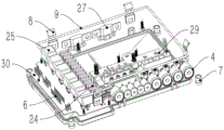
Fig. 2 is a schematic structural diagram of the electric box of the rear battery compartment of the automobile in fig. 1 without an upper cover.
Fig. 3 is a schematic structural diagram of the electric box of the rear battery compartment of the automobile in fig. 2 without a main shell.
Fig. 4 is a schematic structural diagram of the electric box of the rear battery compartment of the automobile in fig. 3 without an electromagnetic switch.
Fig. 5 is a schematic structural diagram of an installation tray of the automobile rear battery compartment electric box.
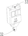
Fig. 6 is a schematic structural diagram of a plug terminal of the automobile rear battery compartment electrical box.
Fig. 7 is a schematic structural diagram of the backup fuse of the automobile rear battery compartment electrical box of the invention.
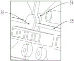
Fig. 8 is a schematic structural view of a bottom window of the automobile rear battery compartment electrical box.
Fig. 9 is a schematic structural diagram of a backup relay of the automobile rear battery compartment electrical box of the invention.
In the figure, 1 is an upper cover, 2 is a main shell, 3 is a lower cover, 4 is a rubber sleeve, 5 is a spare relay hanger, 6 is a connector, 7 is a screw hole, 8 is a hanging buckle, 9 is a rubber strip, 21 is an electromagnetic switch, 22 is a copper bar, 23 is a fuse, 24 is a mini-type relay, 25 is an auto-type safety piece, 26 is a partition plate, 27 is a spare safety, 28 is a spare safety slot, 29 is a connecting plate, 30 is a PCB (printed circuit board), 31 is a mounting tray, 32 is a fixing pin, 33 is a plug opening, 34 is an opening window, 35 is a convex edge, 36 is a cover plate, 37 is a pin interface, and 38 is a sliding groove.
Detailed Description
The following examples are intended to illustrate the present invention in detail and should not be construed as limiting the scope of the present invention in any way.
The unit modules, components, structures, mechanisms, sensors, and other devices referred to in the following examples are all conventional commercially available products unless otherwise specified.
In the description of the present application, it is to be understood that the terms "upper", "lower", "front", "rear", "left", "right", "top", "bottom", "inner", "outer", and the like, indicate orientations or positional relationships based on the orientations or positional relationships shown in the drawings, are merely for convenience in describing the present application and simplifying the description, and do not indicate or imply that the device or element being referred to must have a particular orientation, be constructed in a particular orientation, and be operated, and thus, should not be construed as limiting the present application. References to "first," "second," etc. in this application are intended to distinguish between similar items and not necessarily to describe a particular order or sequence.
Example 1: the utility model provides a storage battery storehouse electrical apparatus box behind car, refers to fig. 1, includes the casing, and the casing is inside to contain control circuit, and this casing includes upper cover 1, main part 2, lower cover 3, and the front end lateral wall of main part 2 is equipped with 9 waterproof line gum covers 4 of crossing, can insert and effectively protect the protection level that improves the product with outside cable. Altogether 4 connectors 6 are drawn forth in the left side of casing 1, including 3 2.8 series of connectors and 1 1.3mm circular connector, at casing 1's right side installation standby relay pendant 5, set up reserve insurance slot 28 in casing 1's rear side, can directly take spare part to change convenient and fast when the device in the casing breaks down. Upper cover 1 adopts the preparation of PC transparent material, and 2 connect fixedly through hanging to detain 8 with the main part, hang to detain 8 and set up 2, 1 respectively at the rear side of main part, the right side, the front side corresponds respectively, it sets up the OPEN typeface to correspond the position of detaining at the upper cover, facilitate the use, lower cover 3 and main part 2 pass through the installation of screw hole 7 cooperation fastening screw, the peripheral design of main part has the above-mentioned screw hole 7 of 4 10mm diameters, the internal design has the metal support steel bushing, a hole for strengthening the fixed orifices and bearing the moment of torsion.
The binding position of upper cover 1 and main part 2 is equipped with the waterproof foaming silica gel strip 9 of 5mm diameter, improve sealed level, refer to fig. 2 to 4, inside main part 2, the rear right side is 2 high-power electromagnetic switch 21 for the input and the control of main power supply, high-power electromagnetic switch installs on the relay installation tray 31 of independent design, refer to fig. 5, tray design has multiple electromagnetic switch mounting structure, make things convenient for the customer to install different specification electromagnetic switch, the tray adopts 4M 5 nuts to be fixed with the main part. The copper bar 22, as an output of the electromagnetic switch, is electrically connected to the adjacent fuse 23. Fuse 23 includes the little fuse of 4 left sides and the big fuse of 4 right sides, and their output and the cable plug terminal fixed connection of gum cover 4 parcel, fuse 23 installs on the copper post, sets up connecting plate 29 on its input copper post, forms electric parallel.
An isolation bin is arranged on the left side of the main body 2, and a PCB 30 is contained in the bin and used for realizing a circuit principle. The circuit board is soldered with a plug terminal, see fig. 6, whose fixing pin 32 is soldered on the circuit board, and the insertion opening 33 is used to fix the pin of the electrical component and form the electrical connection. The left side of PCB circuit board 30 is mini type relay 24, and the right side is auto type rupture disc 25, and the upper surface in isolation storehouse is equipped with baffle 26, is equipped with the fretwork on the baffle, and mini type relay 24 and auto type rupture disc 25 are separated in each fretwork, and easy to assemble and stability are strong.
Set up the separation storehouse through the left side, right side top sets up tray, right side below and sets up the terminal, with 2 inside 3 parts that divide into mutual isolation of main part, rely on the copper bar to form electrical connection between them simultaneously, pack the structure of moulding plastics at the clearance main part 2 of each part, wrap up electric element wherein, increase stability. The PCB circuit board 30 is connected to an external connector 6 for input and output of control signals, and the fuse 23 is connected to an external cable interface for output of driving current.
Set up reserve insurance slot and reserve relay slot in the outside of main part 2, reserve insurance slot includes, makes things convenient for follow-up extension. The spare safety slot comprises an opening and a pressing block, referring to fig. 7, the upper opening and the lower slot are the same in size, the lower part can be conveniently plugged with a small safety, the upper part can be plugged with a large safety, and the pressing block and the spare safety 27 are in interference fit with each other through pins and are prevented from sliding out by means of friction and pressure. The stand-by relay slot on main part 2 right side then adopts the form of plug terminal parcel injection molding, and the pin interface 37 that corresponds with plug terminal is set up on the injection molding top, and the lateral wall of injection molding then contains the spout, and the corresponding sets up the slide rail at main part 2 lateral wall, and the two cooperation relies on the frictional force during to fix.
The combination position of lower cover 3 and main part 2 is equipped with the waterproof foaming silica gel strip of 5mm diameter, and the lower cover design has 4 screw holes 7 and 2 butt joints of main part, and the design of lower cover below has ventilative structure, prevents that the air from condensing. The ventilation structure comprises a window 34, a rib 35 is further arranged on the lower cover 3, a cover plate 36 is arranged above the window 34, and the cover plate 36 is fixed on the rib 35.
The electric box of the automobile rear storage battery compartment is compact, the electromagnetic switch is provided with the tray structure, the front installation and the disassembly are facilitated, various electromagnetic switch installation and fixing structure points are designed, and the installation of various electromagnetic switches can be facilitated according to customer requirements. The PCB is separated out independently through the design of the isolation bin, modular production is facilitated, the outlet end is sealed through a secondary injection molding encapsulation structure, and high strength can be achieved in a small space. The design of rubber protection position has the structure point of windowing, not only has fine sealed, can be very light moreover with the point of windowing get rid of insert installation cable
While the present invention has been described in detail with reference to the drawings and the embodiments, those skilled in the art will understand that various specific parameters in the above embodiments can be changed without departing from the spirit of the present invention, and a plurality of specific embodiments are formed, which are common variation ranges of the present invention, and will not be described in detail herein.
Claims (9)
1. The utility model provides a storage battery storehouse electrical apparatus box behind car, includes casing and internal control module, its characterized in that, the casing includes upper cover, main part, lower cover, be equipped with installation tray, fixed column, isolation storehouse in the main part, the installation tray internal fixation has electromagnetic switch, the inner wall of installation tray with electromagnetic switch laminating, be equipped with the fuse on the fixed column, be equipped with the circuit board in the isolation storehouse, be equipped with control element on the circuit board, the upper surface in isolation storehouse is equipped with the baffle, be equipped with on the baffle with the fretwork that control element corresponds.
2. The electrical box of the automobile rear battery compartment as claimed in claim 1, wherein the mounting tray, the fixing column and the isolation compartment are fixedly connected by a copper plate.
3. The electrical box of the automobile rear battery compartment as claimed in claim 1, wherein the upper cover is made of a PC transparent material, and at least two buckles butted with the main body are arranged on the edge of the upper cover.
4. The electric box of the automobile rear battery compartment as claimed in claim 3, wherein a waterproof foamed silica gel strip with a diameter of 5mm is arranged at the joint position of the upper cover and the main body.
5. The electrical box of the automobile rear battery compartment as claimed in claim 1, wherein a cable plug terminal is arranged at the output end of the fuse, and a waterproof wire-passing rubber sleeve is arranged on the cable plug terminal.
6. The electrical box of the automobile rear battery compartment as claimed in claim 5, wherein an integrally molded copper bar is arranged at an input end of the fuse, and the fuse is connected in parallel to the copper bar and fixed by screws.
7. The electrical box of the automobile rear battery compartment as claimed in claim 1, wherein a first slot for mounting a spare fuse is formed in a first side wall of the housing, the first slot comprises an upper slot and a lower slot, the upper slot and the lower slot both comprise an opening and a pressing block, the opening of the upper slot and the edge of the lower slot are flush, and the pressing block and the spare fuse are in interference fit.
8. The electric box of the automobile rear battery compartment as claimed in claim 1, wherein a second slot for mounting the backup relay is formed in a second side wall of the housing, the second slot comprises a clamping terminal and a rectangular injection molded body wrapped outside the clamping terminal, and a sliding groove is formed in a side wall of the rectangular injection molded body.
9. The electric box of rear battery compartment of automobile as claimed in claim 1, wherein the lower cover has an air hole in its center, and an X-shaped rib is provided on the lower cover, and a hole cover is provided above the air hole and fixedly connected to the rib.
Priority Applications (1)
| Application Number | Priority Date | Filing Date | Title |
|---|---|---|---|
| CN202010801695.9A CN111786269A (en) | 2020-08-11 | 2020-08-11 | Automobile rear battery compartment electrical box |
Applications Claiming Priority (1)
| Application Number | Priority Date | Filing Date | Title |
|---|---|---|---|
| CN202010801695.9A CN111786269A (en) | 2020-08-11 | 2020-08-11 | Automobile rear battery compartment electrical box |
Publications (1)
| Publication Number | Publication Date |
|---|---|
| CN111786269A true CN111786269A (en) | 2020-10-16 |
Family
ID=72762415
Family Applications (1)
| Application Number | Title | Priority Date | Filing Date |
|---|---|---|---|
| CN202010801695.9A Pending CN111786269A (en) | 2020-08-11 | 2020-08-11 | Automobile rear battery compartment electrical box |
Country Status (1)
| Country | Link |
|---|---|
| CN (1) | CN111786269A (en) |
Cited By (1)
| Publication number | Priority date | Publication date | Assignee | Title |
|---|---|---|---|---|
| CN112601408A (en) * | 2020-12-25 | 2021-04-02 | 珠海格力电器股份有限公司 | Electrical apparatus box, controller and ECAS pneumatic system |
-
2020
- 2020-08-11 CN CN202010801695.9A patent/CN111786269A/en active Pending
Cited By (2)
| Publication number | Priority date | Publication date | Assignee | Title |
|---|---|---|---|---|
| CN112601408A (en) * | 2020-12-25 | 2021-04-02 | 珠海格力电器股份有限公司 | Electrical apparatus box, controller and ECAS pneumatic system |
| CN112601408B (en) * | 2020-12-25 | 2023-08-25 | 珠海格力电器股份有限公司 | Electrical apparatus box, controller and ECAS pneumatic system |
Similar Documents
| Publication | Publication Date | Title |
|---|---|---|
| KR100387445B1 (en) | Fuse with relay box for automobil | |
| US6430054B1 (en) | Electrical junction box | |
| US20070147017A1 (en) | Integrated electronic module structure for vehicles | |
| CN102892633A (en) | Safety device for high-voltage components | |
| CN111786269A (en) | Automobile rear battery compartment electrical box | |
| CN215590496U (en) | High-voltage distribution box and battery pack | |
| CN117293477B (en) | Distribution box and battery pack | |
| CN212277627U (en) | Automobile rear battery compartment electrical box | |
| CN212148723U (en) | Modularized main distribution box for automobile | |
| CN209676644U (en) | Electrical appliance kit and heavy truck | |
| CN203573922U (en) | Fuse box of front cabinet of automobile or electric car | |
| CN216942970U (en) | Control box, battery and power consumption device | |
| CN215751955U (en) | Low-voltage power supply system and vehicle with same | |
| CN207819187U (en) | A kind of plug-wire type distribution box | |
| CN213028822U (en) | Domain controller and vehicle with same | |
| CN215772569U (en) | Power distribution device and traffic transportation device with same | |
| CN200960894Y (en) | Automobile electric power main fuse box | |
| CN212447119U (en) | High-voltage distribution box for electric automobile | |
| CN209283073U (en) | Power-supply controller of electric | |
| CN209626173U (en) | A kind of novel storage battery fuse box | |
| CN112955344A (en) | High-voltage power distribution module and high-voltage electric control assembly | |
| CN214215685U (en) | Small-sized distribution box for power distribution of automobile electrical appliances | |
| CN218918768U (en) | Front cabin fuse box of pure electric vehicle | |
| CN214267524U (en) | Novel automobile electrical control box | |
| CN212447118U (en) | High-voltage distribution box for new energy automobile |
Legal Events
| Date | Code | Title | Description |
|---|---|---|---|
| PB01 | Publication | ||
| PB01 | Publication | ||
| SE01 | Entry into force of request for substantive examination | ||
| SE01 | Entry into force of request for substantive examination |