CN111780173A - Household electrical appliance - Google Patents
Household electrical appliance Download PDFInfo
- Publication number
- CN111780173A CN111780173A CN201910271837.2A CN201910271837A CN111780173A CN 111780173 A CN111780173 A CN 111780173A CN 201910271837 A CN201910271837 A CN 201910271837A CN 111780173 A CN111780173 A CN 111780173A
- Authority
- CN
- China
- Prior art keywords
- electromagnetic heating
- household appliance
- air inlet
- air outlet
- air
- Prior art date
- Legal status (The legal status is an assumption and is not a legal conclusion. Google has not performed a legal analysis and makes no representation as to the accuracy of the status listed.)
- Pending
Links
Images


Classifications
-
- F—MECHANICAL ENGINEERING; LIGHTING; HEATING; WEAPONS; BLASTING
- F24—HEATING; RANGES; VENTILATING
- F24C—DOMESTIC STOVES OR RANGES ; DETAILS OF DOMESTIC STOVES OR RANGES, OF GENERAL APPLICATION
- F24C7/00—Stoves or ranges heated by electric energy
-
- F—MECHANICAL ENGINEERING; LIGHTING; HEATING; WEAPONS; BLASTING
- F24—HEATING; RANGES; VENTILATING
- F24C—DOMESTIC STOVES OR RANGES ; DETAILS OF DOMESTIC STOVES OR RANGES, OF GENERAL APPLICATION
- F24C15/00—Details
- F24C15/08—Foundations or supports plates; Legs or pillars; Casings; Wheels
-
- F—MECHANICAL ENGINEERING; LIGHTING; HEATING; WEAPONS; BLASTING
- F24—HEATING; RANGES; VENTILATING
- F24C—DOMESTIC STOVES OR RANGES ; DETAILS OF DOMESTIC STOVES OR RANGES, OF GENERAL APPLICATION
- F24C15/00—Details
- F24C15/20—Removing cooking fumes
- F24C15/2042—Devices for removing cooking fumes structurally associated with a cooking range e.g. downdraft
-
- F—MECHANICAL ENGINEERING; LIGHTING; HEATING; WEAPONS; BLASTING
- F24—HEATING; RANGES; VENTILATING
- F24C—DOMESTIC STOVES OR RANGES ; DETAILS OF DOMESTIC STOVES OR RANGES, OF GENERAL APPLICATION
- F24C7/00—Stoves or ranges heated by electric energy
- F24C7/06—Arrangement or mounting of electric heating elements
- F24C7/067—Arrangement or mounting of electric heating elements on ranges
Abstract
The application discloses a household appliance. The household appliance comprises a shell, an electromagnetic heating device arranged in the shell and a smoke exhaust ventilator arranged in the shell, wherein the smoke exhaust ventilator is positioned below the electromagnetic heating device. In the household appliance of the embodiment of the application, the electromagnetic heating device and the range hood device are integrated in the same shell, so that the household appliance occupies a small space and is more miniaturized and integrated; in addition, the oil fume pumping device is positioned below the electromagnetic heating device, and can pump oil fume, water vapor and the like near the electromagnetic heating device, so that the cleanness of a kitchen is ensured.
Description
Technical Field
The application relates to the technical field of household appliances, in particular to a household appliance.
Background
With the improvement of living standard of people, the range hood becomes a necessary household appliance in families. The smoke exhaust ventilator can extract oil smoke, water vapor and sundries in a kitchen to reduce the amount of oil smoke sucked by a user and avoid the harm of harmful substances such as the oil smoke to the user. Generally, smoke ventilator installs the wall in top or top of a kitchen range one side, and so, smoke ventilator occupies the space great, is unfavorable for user experience.
Disclosure of Invention
The present application is directed to solving at least one of the problems in the prior art. To this end, the present application provides a household appliance.
The household appliance comprises a shell, an electromagnetic heating device and a range hood device, wherein the electromagnetic heating device is arranged in the shell, the range hood device is arranged in the shell, and the range hood device is located below the electromagnetic heating device.
In the household appliance of the embodiment of the application, the electromagnetic heating device and the range hood device are integrated in the same shell, so that the household appliance occupies a small space and is more miniaturized and integrated; in addition, the oil fume pumping device is positioned below the electromagnetic heating device, and can pump oil fume, water vapor and other gases near the electromagnetic heating device, so that the cleanness degree of a kitchen is ensured.
In some embodiments, the housing includes an outer frame and a partition disposed in the outer frame, the partition and the outer frame form a first receiving space and a second receiving space, the electromagnetic heating device is received in the first receiving space, and the range hood is received in the second receiving space.
In some embodiments, the outer frame includes a bottom plate, a side plate connected to the bottom plate, and a panel connected to the side plate and opposite to the bottom plate, the panel, the side plate, and the partition plate enclose the first receiving space, and the side plate, the bottom plate, and the partition plate enclose the second receiving space.
In some embodiments, the panel is formed with an air inlet communicated with the first receiving space, the side plate is formed with an air outlet communicated with the second receiving space, an air duct penetrating through the first receiving space and the second receiving space is formed between the air inlet and the air outlet, and the range hood is configured to establish an air flow from the air inlet to the air outlet.
In some embodiments, the range hood includes a volute and a fan disposed in the volute, the volute is formed with an air inlet and an air outlet, the partition is formed with a through hole communicating the first receiving space and the second receiving space, and the through hole is communicated with the air inlet; the fan is used for establishing air flow from the air inlet to the air outlet.
In some embodiments, the air inlet and the through hole are aligned, and the range hood further includes an isolation mesh disposed between the through hole and the air inlet and covering the air inlet.
In some embodiments, the range hood includes a purification module connected to the volute and butted to the air outlet, and the purification module includes an ozone purification component and an activated carbon purification component, and the ozone purification component and the activated carbon component are sequentially arranged along a direction from the air outlet to the air outlet.
In some embodiments, the electromagnetic heating device comprises a carrier, an electromagnetic heating unit disposed in the carrier, and a control component disposed in the carrier for controlling an operating state of the electromagnetic heating unit.
In some embodiments, the number of the electromagnetic heating units is multiple, and the multiple electromagnetic heating units are arranged in an array.
In some embodiments, the carrier is formed with heat dissipation apertures.
Additional aspects and advantages of embodiments of the present application will be set forth in part in the description which follows and, in part, will be obvious from the description, or may be learned by practice of embodiments of the present application.
Drawings
The above and/or additional aspects and advantages of the present application will become apparent and readily appreciated from the following description of the embodiments, taken in conjunction with the accompanying drawings of which:
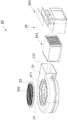
fig. 1 is a schematic perspective view of a home appliance according to an embodiment of the present application;
fig. 2 is a perspective exploded schematic view of a home appliance according to an embodiment of the present application;
FIG. 3 is an exploded perspective view of a housing according to an embodiment of the present application;
fig. 4 is a perspective exploded schematic view of a range hood according to an embodiment of the present application;
FIG. 5 is a schematic perspective view of a separator plate according to an embodiment of the present application;
FIG. 6 is a schematic perspective exploded view of an ozone purification assembly according to an embodiment of the present application;
FIG. 7 is a schematic exploded perspective view of an activated carbon purification assembly according to an embodiment of the present application;
fig. 8 is a schematic perspective exploded view of an electromagnetic heating apparatus according to an embodiment of the present application;
fig. 9 is a partially exploded perspective view of a home appliance according to an embodiment of the present application.
Description of the main element symbols: the household appliance 100, the housing 10, the outer frame 11, the bottom plate 111, the side plate 112, the first plate 1121, the first upper long edge 1123, the first lower long edge 1124, the first receiving portion 1125, the first mounting portion 1126, the second plate 1122, the second upper long edge 1127, the second lower long edge 1128, the second receiving portion 1129, the second mounting portion 112a, the short edge 112b, the third mounting portion 112c, the first screw hole 112d, the second screw hole 112e, the air outlet 112f, the fourth screw hole 112g, the panel 113, the first air inlet 1131, the button hole 1132, the operation mark 1133, the partition 12, the receiving groove 121, the fourth mounting portion 122, the third screw hole 123, the first through hole 124, the boss 125, the annular portion 1251, the second through hole 1252, the first receiving space 13, the second receiving space 14, the air duct, the cooking fume extractor 20, the scroll 21, the air inlet 211, the air outlet 212, the fan 22, the separation net 23, the separation hole 232, the filter structure 24, the mounting ring 241, the filter screen 242, the purification module 25, the ozone purification assembly 251, the housing 2511, the ozone generating frame 2512, the connecting plate 251a, the connecting column 251b, the coil 2513, the grid 2514, the activated carbon purification assembly 252, the accommodating frame 2521, the third through hole 252a, the fifth mounting portion 252b, the accommodating member 2522, the cover 252c, the electromagnetic heating device 30, the bearing frame 31, the reinforcement frame 311, the fourth through hole 3111, the second air inlet 3112, the protrusion 3113, the groove 3114, the sixth mounting portion 311a, the bottom case 312, the third accommodating space 3121, the second heat dissipation hole 3122, the bearing member 313, the heat dissipation structure 3131, the first heat dissipation hole 3132, the bearing seat 3133, the electromagnetic heating unit 32, the control component 33, the control chip 331, and the button 332.
Detailed Description
Reference will now be made in detail to embodiments of the present application, examples of which are illustrated in the accompanying drawings, wherein like or similar reference numerals refer to the same or similar elements or elements having the same or similar function throughout. The embodiments described below with reference to the accompanying drawings are illustrative and are only for the purpose of explaining the present application and are not to be construed as limiting the present application.
In the description of the present application, it is to be understood that the terms "center," "longitudinal," "lateral," "length," "width," "thickness," "upper," "lower," "front," "rear," "left," "right," "vertical," "horizontal," "top," "bottom," "inner," "outer," "clockwise," "counterclockwise," and the like are used in the orientations and positional relationships indicated in the drawings for convenience in describing the present application and for simplicity in description, and are not intended to indicate or imply that the referenced devices or elements must have a particular orientation, be constructed in a particular orientation, and be operated in a particular manner, and are not to be construed as limiting the present application. Furthermore, the terms "first", "second" and "first" are used for descriptive purposes only and are not to be construed as indicating or implying relative importance or implicitly indicating the number of technical features indicated. Thus, features defined as "first", "second", may explicitly or implicitly include one or more of the described features. In the description of the present application, "a plurality" means two or more unless specifically limited otherwise.
In the description of the present application, it is to be noted that, unless otherwise explicitly specified or limited, the terms "mounted," "connected," and "connected" are to be construed broadly, e.g., as meaning either a fixed connection, a removable connection, or an integral connection; may be mechanically connected, may be electrically connected or may be in communication with each other; either directly or indirectly through intervening media, either internally or in any other relationship. The specific meaning of the above terms in the present application can be understood by those of ordinary skill in the art as appropriate.
In this application, unless expressly stated or limited otherwise, the first feature "on" or "under" the second feature may comprise direct contact of the first and second features, or may comprise contact of the first and second features not directly but through another feature in between. Also, the first feature being "on," "above" and "over" the second feature includes the first feature being directly on and obliquely above the second feature, or merely indicating that the first feature is at a higher level than the second feature. A first feature being "under," "below," and "beneath" a second feature includes the first feature being directly under and obliquely below the second feature, or simply meaning that the first feature is at a lesser elevation than the second feature.
The following disclosure provides many different embodiments or examples for implementing different features of the application. In order to simplify the disclosure of the present application, specific example components and arrangements are described below. Of course, they are merely examples and are not intended to limit the present application. Moreover, the present application may repeat reference numerals and/or letters in the various examples, such repetition is for the purpose of simplicity and clarity and does not in itself dictate a relationship between the various embodiments and/or configurations discussed. In addition, examples of various specific processes and materials are provided herein, but one of ordinary skill in the art may recognize applications of other processes and/or use of other materials.
Referring to fig. 1 and 2, a household appliance 100 according to an embodiment of the present invention includes a housing 10, a range hood device 20, and an electromagnetic heating device 30. The electromagnetic heating device 30 and the range hood 20 are both disposed in the housing 10, and the range hood 20 is located below the electromagnetic heating device 30.
In the household electrical appliance 100 of the embodiment of the present application, the range hood 20 and the electromagnetic heating device 30 are detachably integrated in the same housing 10, the range hood 20 is disposed below the electrical heating device, the household electrical appliance 100 is normally used and normally placed (as shown in fig. 1), the relative position relationship between the range hood 20 and the electromagnetic heating device 30 is the up-down relationship, so the household electrical appliance 100 is more miniaturized and integrated, the occupied space is small, the space utilization rate of the kitchen with relatively crowded space is improved, the range hood 20 and the electromagnetic heating device 30 can be separated up and down, and the whole structure of the household electrical appliance 100 is convenient for assembly and disassembly.
The electromagnetic heating device 30 is arranged on the upper half part of the household appliance 100, so that the use habit of a user is met, and the user can cook food conveniently through the electromagnetic heating device 30; the cooking fume extracting device 20 is located at the lower half portion of the household appliance 100, that is, the cooking fume extracting device 20 is located below the electromagnetic heating device 30, the cooking fume extracting device 20 can generate suction force to extract and purify air, when a user cooks food through the electromagnetic heating device 30, generated cooking fume, vapor and the like float in the air near the electromagnetic heating device 30 or in the space of a kitchen or are deposited downwards, the generated cooking fume, vapor and the like can be extracted and purified by the cooking fume extracting device 20, cleanness of the household appliance 100 and the kitchen is guaranteed, and labor of the user in cleaning the kitchen can be reduced.
When the user uses the household appliance 100, if only the electromagnetic heating device 30 is needed to cook food, or the cooking device 30 needs to be turned on to save electricity if less oil smoke, water vapor and the like are generated or no oil smoke, water vapor and the like are generated, and the oil smoke exhaust device 20 does not need to be turned on; if cooking is finished or oil smoke, water vapor and the like are left in the room, the oil smoke device 20 can be independently started only by pumping the oil smoke, the water vapor and the like in the room without starting the electromagnetic heating device 30 so as to save the use of electric quantity; or, when cooking food, the electromagnetic heating device 30 and the cooking fume extractor 20 are turned on simultaneously to remove the cooking fume, water vapor and impurities generated during cooking in time, so as to keep the kitchen clean and sanitary.
Referring to fig. 1, in an example, the household appliance 100 has a substantially rectangular shape, which is regular and beautiful and is easy to assemble. Of course, the shape of the household appliance 100 is substantially rectangular, which is only an example, and in further embodiments, the household appliance 100 may also be a square, a cylinder, or other regular or irregular shapes, and in particular embodiments, the shape may be specifically configured.
In an embodiment, the household appliance 100 may be disposed on a cooking bench (not shown) of a kitchen, an accommodating space (not shown) adapted to the household appliance 100 is formed on the cooking bench, and the household appliance 100 is embedded in the accommodating space, so that the household appliance 100 has better stability and is more convenient to detach. The surface of the household appliance 100 may be flush with or slightly higher or lower than the top of the cooking bench, that is, the height of the household appliance 100 is equal to or close to the height of the accommodating space, so that it is convenient for the user to cook food and clean the top of the cooking bench.
The length of the household appliance 100 may be similar to or equal to the length of the accommodating space, and the width of the household appliance 100 may also be similar to or equal to the width of the accommodating space. When the height, width and length of the household appliance 100 are equal to those of the accommodating space, the impurities (such as food) in the kitchen can be prevented from falling into the accommodating space of the cooking bench, and the cleanness of the cooking bench and the kitchen is ensured.
In one embodiment, the household appliance 100 and the cooking bench may be integrated into a single structure, and the household appliance 100 and the cooking bench are detachably integrated together, so that the household appliance 100 and the cooking bench have high matching degree and integration degree, and the kitchen and the cooking bench are arranged in the kitchen space without additional modification (such as building the cooking bench in the kitchen, forming an accommodating space on the cooking bench, etc.), so that the food can be cooked daily through the cooking bench and the household appliance 100 integrated on the cooking bench; if the user needs to reform transform the fitment to the kitchen, remove the top of a kitchen range and can vacate the space in kitchen, be convenient for construct. More, kitchen appliances, such as cupboards, dish washing grooves, dish washing machines, storage cabinets and the like, electric appliances and the like can be arranged on the cooking bench, so that the integration of the electric appliances and the cooking appliances in the kitchen is further improved, and the space utilization rate of the kitchen is further improved.
In one example, the housing 10 may be made of metal, which is easily available, has high strength and high protection, and can better bear and protect the electromagnetic heating device 30 and the range hood 20 disposed in the housing 10.
It can be understood that the electromagnetic heating device 30 can be a cooking appliance such as an electromagnetic oven or a gas stove for cooking food, and the range hood device can be a range hood, an exhaust fan, or other devices with an air exhaust function. The electromagnetic heating device 30 according to the embodiment of the present application is exemplified by an electromagnetic oven, and the range hood is exemplified by the range hood 20. Furthermore, the range hood 20 of the household appliance 100 can also be used as an air purifier to suck and purify air in the kitchen, and the purified air can be discharged into the kitchen for recycling, so as to promote the air flow in the kitchen.
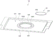
Referring to fig. 2 and 3, in some embodiments, the housing 10 includes an outer frame 11 and a partition 12 disposed in the outer frame 11, the partition 12 and the outer frame 11 form a first receiving space 13 and a second receiving space 1414, the electromagnetic heating device 30 is received in the first receiving space 13, and the range hood 20 is received in the second receiving space 14.
The first receiving space 13 and the second receiving space 14 can better protect the electromagnetic heating device 30 and the range hood 20, reduce or prevent the electromagnetic heating device 30 and the range hood 20 from being affected by oil smoke, water vapor and impurities, prevent the electromagnetic heating device 30 and the range hood 20 from being contaminated and from being dirty and damp, even influence the normal use of the electromagnetic heating device 30 and the range hood 20, and also prevent a user from mistakenly operating to stretch a hand into the household appliance 100, so that the household appliance has higher safety protection performance.
The partition board 12 partitions the household appliance 100 into two parts, so that the first receiving space 13 and the second receiving space 14 become two relatively independent spaces, the electromagnetic heating device 30 is received in the first receiving space 13, and the range hood 20 is received in the second receiving space 14, thereby preventing the electromagnetic heating device 30 and the range hood 20 from being affected with each other (for example, the electromagnetic heating device 30 and the range hood 20 generate heat to cause higher temperature, etc.), ensuring the normal operation of the electromagnetic heating device 30 and the range hood 20, and easily arranging the electromagnetic heating device 30 and the range hood 20 in the household appliance 100, facilitating assembly and disassembly, and reducing the implementation difficulty of the scheme.
Referring to fig. 3, in some embodiments, the outer frame 11 includes a bottom plate 111, side plates 112 and a panel 113. The side plate 112 is connected to the bottom plate 111, and the panel 113 is connected to the side plate 112 and faces the bottom plate 111. The side plate 112, the panel 113 and the partition plate 12 enclose a first receiving space 13. The bottom plate 111, the side plate 112 and the partition plate 12 enclose a second accommodating space 14.
It is understood that the bottom plate 111 is disposed at the bottom of the household appliance 100, the panel 113 is disposed at the top of the household appliance 100, a user can place the cooking utensil on the panel 113 to cook food, and the side plates 112 are disposed around the household appliance 100 to protect electric components and the like in the household appliance 100. The bottom plate 111, the side plate 112 and the panel 113 are substantially rectangular, so as to be assembled and fixed together, and the bottom plate 111, the side plate 112 and the panel 113 are fixedly connected to form the substantially rectangular household appliance 100.
Referring to fig. 3, in some embodiments, the side panel 112 includes a first plate 1121 disposed in the length direction of the household appliance 100 and a second plate 1122 disposed in the width direction of the household appliance 100. The first plate 1121 and the second plate 1122 are each generally rectangular. The first plate 1121 includes a first upper long edge 1123 and a first lower long edge 1124, the first upper long edge 1123 being adjacent to the panel 113, and the first lower long edge 1124 being adjacent to the bottom panel 111.
The first upper long edge 1123 extends outwards of the household appliance 100 to form a first receiving part 1125, and the first lower long edge 1124 extends inwards of the household appliance 100 to form a first mounting part 1126; the second plate 1122 includes a second upper long edge 1127 and a second lower long edge 1128, the second upper long edge 1127 extends outward of the household appliance 100 to form a second receiving portion 1129, and the second lower long edge 1128 extends inward of the household appliance 100 to form a second mounting portion 112 a.
The first receiving portion 1125 and the second receiving portion 1129 are used for receiving the panel 113, and the first mounting portion 1126 and the second mounting portion 112a are used for being fixedly connected with the bottom plate 111; the second plate 1122 further includes a short edge 112b, the short edge 112b extends into the household appliance 100 to form a third mounting portion 112c, and the third mounting portion 112c is used for closing a connection portion between the first plate 1121 and the second plate 1122.
The first receiving portion 1125, the second receiving portion 1129, the first mounting portion 1126, the second mounting portion 112a and the third mounting portion 112c are all in the shape of a sheet. The first receiving portion 1125 and the second receiving portion 1129 are sheet-shaped, so that the panel 113 carried on the first receiving portion 1125 and the second receiving portion 1129 can be received more stably. The first mounting portion 1126 and the second mounting portion 112a are sheet-shaped, so that the side plate 112 and the bottom plate 111 can be more tightly and stably fixedly connected. The third mounting portion 112c is shaped as a plate to tightly and firmly fix and connect the first plate 1121 and the second plate 1122.
The first and second mounting portions 1126, 112a are formed with first screw holes 112d, the edge of the bottom plate 111 is formed with second screw holes 112e, the first screw holes 112d correspond to the second screw holes 112e, and the first and second screw holes 112d, 112e can be inserted through screws to fixedly connect the bottom plate 111 and the side plate 112. That is, the side plate 112 and the bottom plate 111 can be fixedly arranged in a screw fastening manner, the screw fastening manner has high repeatability, good stability and convenient disassembly, and the screws and the screw holes are conveniently arranged on the side plate 112 and the bottom plate 111, thereby being beneficial to the assembly and disassembly of the household appliance 100. More, the side plate 112 and the bottom plate 111 may be fixedly connected by rivet anchoring or welding, and the method is not limited to the above-mentioned screw fastening method.
Screw holes may also be formed at the edges of the third mounting portion 112c and the first plate 1121 near the third mounting portion 112c, and the screw holes are formed through screws to further improve the connection stability between the first plate 1121 and the second plate 1122. The panel 113 may be fixedly and non-fixedly carried on the side plate 112 (on the first receiving portion 1125 and the second receiving portion 1129), in the embodiment of the present application, the panel 113 is non-fixedly carried on the side plate 112, that is, the panel 113 may be separated from the first receiving portion 1125 and the second receiving portion 1129.
One side of the partition 12 facing the bottom plate 111 protrudes toward the bottom plate 111 and forms a containing groove 121, the containing groove 121 can collect oil smoke, condensed water, impurities and the like transmitted to the first containing space 13, so as to avoid affecting the electromagnetic heating device 30 contained in the first containing space 13 and prevent the oil smoke from entering the second containing space 14 to affect the oil smoke extraction device 20, and a user can separate the panel 113 from the household appliance 100 to directly clean the impurities in the containing groove 121.
A fourth mounting portion 122 is formed by extending the peripheral edge of the partition plate 12 toward the bottom plate 111, a third screw hole 123 is formed in the fourth mounting portion 122, a fourth screw hole 112g is formed in the side plate 112 corresponding to the third screw hole 123, and the partition plate 12 is fixed between the side plates 112 by passing through the third screw hole 123 and the fourth screw hole 112g by screws. In an example, a drainage groove (not shown) or a drainage tube (not shown) may be further disposed in the accommodating groove 121 to guide the condensed water and the impurities condensed in the accommodating groove 121 to the outside of the household appliance 100, so that a user does not need to manually clean the condensed water, thereby further ensuring the cleanness of the household appliance 100 and improving the experience of the user.
In one example, the bottom plate 111 and the side plate 112 are made of metal, and the panel 113 is made of glass ceramics. The microcrystalline glass has high mechanical strength, excellent insulating property, less dielectric loss, stable dielectric constant, good chemical corrosion resistance, wear resistance, good thermal stability, high use temperature, convenient cleaning, better adaptation to cooking environment, protection of the electromagnetic heating device 30 below the microcrystalline glass and improvement of the strength of the household appliance 100, and can adjust the thermal expansion coefficient in a larger range.
Referring to fig. 3 and 4, in some embodiments, the panel 113 is formed with a first air inlet 1131 communicated with the first accommodating space 13, the side plate 112 is formed with an air outlet 112f communicated with the second accommodating space 14, an air duct penetrating the first accommodating space 13 and the second accommodating space 14 is formed between the first air inlet 1131 and the air outlet 112f, and the smoke exhaust ventilator 20 is used for establishing an air flow from the first air inlet 1131 to the air outlet 112 f.
Specifically, in the embodiment of this application, the shape of first air inlet 1131 is substantially fillet rectangle, first air inlet 1131 sets up in the both sides of panel 113 along the width direction of panel 113, better adaptation between first air inlet 1131 and the panel 113, the air inlet area is great, passable amount of wind is great, guaranteed fume pumping device 20 to the extraction purification ability of oil smoke, steam and debris etc., simultaneously, the shape of first air inlet 1131 and the position at panel 113 are convenient for set up, reduce the implementation degree of difficulty.
When the user needs to clean the household electrical appliance 100, the panel 113 and the electromagnetic heating device 30 can be lifted up through the first air inlet 1131 (for example, two hands penetrate into the first air inlets 1131 on two sides respectively to grasp the panel 113 and lift up) so as to separate the electromagnetic heating device 30 from the range hood 20 in a labor-saving manner, thereby exposing the first accommodating space 13, and the partition plate 12 is detached to expose the second accommodating space 14, thereby facilitating cleaning the inside of the household electrical appliance 100.
In one example, the first intake port 1131 may have a width ranging from 20mm to 40mm and a length ranging from 250mm to 400 mm.
When the household appliance 100 is turned on, the smoke exhaust ventilator 20 operates and generates airflow from the first air inlet 1131 to the air outlet 112f, and the air inlets 211 arranged at the two sides of the panel 113 extract oil smoke, water vapor, impurities and the like around the household appliance 100, and the oil smoke, the water vapor, the impurities and the like enter the first accommodating space 13 from the air inlets 211 and are transmitted to the air outlet 112f through the air duct in the second accommodating space 14, so that the purified air is discharged from the side surface of the household appliance 100, and the effects of purifying the oil smoke are achieved, and air circulation, environmental protection and energy conservation of a kitchen are facilitated.
More, the air outlet direction of the air outlet 112f may be toward the panel 113 of the household appliance 100; or, the air outlet direction of the air outlet 112f faces the bottom plate 111 direction of the household appliance 100; or, the air outlet direction of the air outlet 112f faces the side plate 112 direction of the household appliance 100; or, the air outlet 112f is communicated with a cabinet of the cooking bench, and the purified air is discharged into the cabinet through the air outlet 112f, so that the purified air can promote the air circulation in the cabinet, and kitchen utensils such as bowls and chopsticks in the cabinet can be dried. In addition, the number of the air outlets 112f may be one or more. The above description of the air outlet direction of the air outlet 112f is only exemplary, and should not be construed as limiting the present application, and the air discharge direction of the air outlet 112f may be specifically set in the specific embodiment.
Furthermore, on the premise of ensuring the air intake amount of the first air inlet 1131, the convenience of disassembling the household appliance 100, and the strength of the panel 113, the first air inlet 1131 may also be disposed at other positions of the panel 113, such as two sides of the panel 113 in the length direction, the middle part of the panel 113, and the like; the first gas inlet 1131 may also have other shapes, such as a regular or irregular shape, for example, a circle, a square, a triangle, a pentagon, etc., and in a specific embodiment, it is sufficient to specifically arrange.
Referring to fig. 4 and 5, in some embodiments, the range hood 20 includes a volute 21 and a fan 22 disposed in the volute 21, the volute 21 is formed with an air inlet 211 and an air outlet 212, the partition 12 is formed with a first through hole 124 communicating the first receiving space 13 and the second receiving space 14, the first through hole 124 is communicated with the air inlet 211, and the fan 22 is configured to establish an air flow from the air inlet 211 to the air outlet 212.
In particular, the fan 22 may divide the drawn soot particles smaller so that the soot particles are more easily disposed of within the range hood 20. One side of the partition board 12 facing the panel 113 protrudes toward the bottom board 111 to form a boss 125 in a circular truncated cone shape, the first through hole 124 is formed on the boss 125, and the boss 125 is located at the middle position of the partition board 12, so that the distances between the first through hole 124 and the first air inlets 1131 at two sides of the panel 113 are close to or equal to each other, and the air flow entering the first accommodating space 13 from the first air inlets 1131 at two sides flows toward the first through hole 124 at the middle part, which can improve the flow rate of the air. The air inlet 211 faces the partition 12 to communicate with the first through hole 124 formed in the partition 12, and both the air inlet 211 and the first through hole 124 are substantially circular, so that a large air inlet area is provided, an air inlet amount can be ensured, and the purification capability of the range hood 20 is further ensured. The air outlet 212 is substantially rectangular, and the air outlet 212 is located in the second accommodating space 14, so that the air flow can be better discharged from the second accommodating space 14.
Referring to fig. 2, 4 and 5, in some embodiments, the air inlet 211 is aligned with the first through hole 124, and the range hood 20 further includes a separation net 23 disposed between the first through hole 124 and the air inlet 211 and covering the air inlet 211.
The air inlet 211 is aligned with the first through hole 124 to ensure that the drawn oil smoke, water vapor, impurities and the like can accurately enter the first through hole 124 from the air inlet 211, so as to reduce the influence of the oil smoke, the water vapor, the impurities and the like on the cleaning of the interior of the household appliance 100, even on the normal use of the household appliance 100. The isolation net 23 separates the fan 22 from other components of the range hood 20, and can play a certain role in filtering and isolating, and can maintain the normal air-extracting process of the fan 22 through the air extracted by the fan 22. The isolation mesh 23 may have a plurality of isolation holes 232 formed thereon, and the isolation holes 232 may be circular or polygonal, for example, in the embodiment of the present application, the isolation holes 232 are circular.
In one example, the filtering structure 24 includes an annular mounting ring 241 and a filtering net 242 disposed in the mounting ring 241, the filtering net 242 may have a plurality of filtering holes (not shown), the aperture of the filtering holes is smaller than the aperture of the isolation hole 232 to better absorb and filter oil smoke, impurities, etc., so as to reduce the influence of the oil smoke, impurities on the isolation net 23 and the fan 22, the filtering net 242 is disposed in the mounting ring 241 for easy replacement, thereby ensuring the cleanness of the oil smoke extraction device 20 and the household appliance 100.
Referring to fig. 3 and 4, in some embodiments, the range hood 20 includes a purification module 25 connected to the spiral casing 21 and butted with the air outlet 212, the purification module 25 includes an ozone purification component 251 and an activated carbon purification component 252, and the ozone purification component 251 and the activated carbon purification component 252 are sequentially arranged along the direction from the air outlet 212 to the air outlet 112 f.
Specifically, the air outlet 212 is connected to the air outlet 112f through the purification module 25, the ozone purification assembly 251 and the activated carbon purification assembly 252 are sequentially arranged in the air duct along the direction from the air outlet 212 to the air outlet 112f, the ozone purification assembly 251 is in butt joint with the air outlet 212, and the activated carbon purification assembly 252 is in butt joint with the air outlet 112 f. The ozone purification assembly 251 is used for generating ozone, the activated carbon purification assembly 252 is used for adsorbing oil smoke, water vapor, sundries and the like, the fan 22 is used for sucking gas from the air outlet 212 during operation, the gas brings the oil smoke, the water vapor, the sundries and the like into the fan, and the oil smoke, the water vapor, the sundries and the like are discharged out of the household appliance 100 from the air outlet 112f after being purified and adsorbed by the ozone purification assembly 251 and the activated carbon purification assembly 252, so that the purposes of removing the oil smoke and purifying the air are achieved. The smoke exhaust ventilator 20 is of a continuous structure in the direction from the air inlet 211 to the air outlet 112f, the air outlet 212 is embedded with the ozone purification component 251, the ozone purification component 251 is embedded with the active carbon purification component 252, the smoke exhaust ventilator 20 is integrally arranged, the appearance is attractive, the structure is compact, the connection is tight and stable, air flow can be prevented from leaking into the household appliance 100 in an air duct, the cleanness of the household appliance 100 is guaranteed, and meanwhile, the smoke exhaust ventilator is easy to assemble and disassemble. The air outlet 112f is formed on the second plate 1122 adjacent to the purification module 25.
Referring to fig. 6, the ozone purifying assembly 251 includes a housing 2511, an ozone generating rack 2512 embedded in the housing 2511, a multi-turn coil 2513 wound on the ozone generating rack 2512, and grilles 2514 embedded at two ends of the housing 2511. Housing 2511 is substantially rectangular. The ozone purifying assembly 251 ionizes air by the coil 2513 to form ozone, the structure of the ozone purifying assembly 251 is simple, and sufficient amount of ozone can be generated to remove odor.
In one embodiment, the ozone generating rack 2512 comprises two connecting plates 251a and a plurality of connecting columns 251b, wherein the two connecting plates 251a are opposite and spaced apart, and the plurality of connecting columns 251b are connected with the two connecting plates 251a and spaced apart. The multi-turn coils 2513 are wound around the plurality of connection posts 251b and are arranged at intervals along the axial direction of the connection posts 251b, wherein an operating voltage is applied between at least two turns of coils 2513 to ionize air to form ozone. As shown in fig. 6, in one example, there are four connection posts 251 b; in another example, there are six connecting posts 251 b; in yet another example, there are eight connection posts 251 b. The above examples of the number of the connection posts 251b are only exemplary, and should not be construed as limiting the present application, and may be specifically configured in specific embodiments.
Both connection plates 251a are insulators to shield the electric field generated by the coil 2513, thereby preventing the electric field from leaking to improve the safety of the ozone purifying assembly 251. In one example, the connection plate 251a may be made of an insulating material such as acryl. The cross section of each connecting plate 251a is rectangular, a plurality of connecting columns 251b enclose a cuboid space, and the multi-turn coils 2513 are uniformly distributed at intervals along the axial direction of the connecting columns 251 b. Because the housing 2511 is substantially in a square cylinder shape and the cross section of the connecting plate 251a is rectangular, the connecting column 251b encloses a rectangular space which can be adapted to the connecting plate 251a, so that the range hood 20 is more compact, and the household appliance 100 is miniaturized.
In one example, the number of the grills 2514 is two, and the two grills 2514 are respectively embedded with the air outlet 212 and the activated carbon purification assembly 252. The grid 2514 can be used to separate the volute 21 from the ozone purification component 251 and the ozone purification component 251 from the activated carbon purification component 252, and can further filter the excessively large oil smoke particles, thereby preventing the excessively large oil smoke particles from entering the ozone purification component 251 and affecting the service life of the ozone purification component 251. In addition, the grating 2514 can be matched with the fan 22 to divide part of the oil smoke particles into smaller particles, so that the purification efficiency of the oil smoke extraction device 20 is ensured.
Referring to fig. 3 and 7, the activated carbon purification assembly 252 includes a receiving frame 2521 and a receiving member 2522, a third through hole 252a is formed at one end of the receiving frame 2521 far away from the ozone purification assembly 251, activated carbon (not shown) is contained in the receiving member 2522, the receiving member 2522 is inserted into the receiving frame 2521 through the third through hole 252a, and a cross-sectional area of the receiving member 2522 is similar to or equal to a cross-sectional area of the receiving frame 2521 to completely seal the air duct, so that the activated carbon contained in the receiving member 2522 is in full contact with air passing through the air duct, thereby achieving a better purification effect, removing odor, and purifying air.
The housing frame 2521 is further formed with a fifth mounting portion 252b extending outward of the housing frame 2521 on both sides of an end thereof away from the ozone purifying assembly 251, the fifth mounting portion 252b can tightly seal the air outlet 112f and the housing frame 2521, the activated carbon purifying assembly 252 can be fixedly disposed on the bottom plate 111 by passing through the housing frame 2521 and the bottom plate 111 via screws, and the fifth mounting portion 252b can be fixedly disposed on the side plate 112 via screws, so as to further improve the stability of the activated carbon purifying assembly 252. The container 2522 includes a cover 252c, the cover 252c can open or close the container 2522, and the activated carbon can be replaced by opening the cover 252 c.
In one embodiment, the activated carbon may be directly inserted into the third through hole 252a, a plurality of communicated filtering holes may be formed on the activated carbon, the filtering holes are arranged in an array, and the filtering holes may be circular or polygonal, so that the gas passes through the activated carbon module, and a better purification effect is achieved.
Referring to fig. 8, in some embodiments, the electromagnetic heating device 30 includes a carrier 31, an electromagnetic heating unit 32, and a control part 33. The electromagnetic heating unit 32 is disposed in the carrier 31, and the control part 33 is disposed on the carrier 31 and is used to control the operating state of the electromagnetic heating unit 32.
Specifically, the carrier 31 includes a reinforcing frame 311, a bottom case 312 and a carrier 313, the reinforcing frame 311 is disposed under the panel 113, the reinforcing frame 311 is supported on an edge of the bottom case 312, the carrier 313 is disposed in the bottom case 312, the electromagnetic heating unit 32 is disposed on the carrier 313 and is accommodated in the bottom case 312, the carrier 313 separates the electromagnetic heating unit 32 from the bottom case 312, and the control component 33 is connected to the electromagnetic heating unit 32 and is located between the electromagnetic heating unit 32 and the reinforcing frame 311.
Referring to fig. 9, the reinforcing frame 311 is disposed corresponding to the panel 113 to reinforce the strength of the panel 113, a fourth through hole 3111 is formed in the reinforcing frame 311, and the electromagnetic heating unit 32 can be exposed from the fourth through hole 3111 to directly heat the panel 113. A sixth mounting portion 311a is formed at an edge of the fourth through hole 3111 facing the bottom case 312, and the sixth mounting portion 311a may be embedded in the bottom case 312 to improve stability among the panel 113, the reinforcing frame 311, and the bottom case 312.
The two ends of the reinforcing frame 311 are provided with second air inlets 3112 corresponding to the first air inlets 1131, and the user's hand can pass through the first air inlets 1131 and the second air inlets 3112 to lift the panel 113 and the reinforcing frame 311. The size of the first air inlet 1131 is equal to or similar to that of the second air inlet 3112, a protrusion 3113 is formed on the edge of the second air inlet 3112 extending from the reinforcing frame 311 to the panel 113, and the protrusion 3113 can be embedded in the first air inlet 1131 to tightly connect the reinforcing frame 311 and the panel 113, so as to reduce or prevent the air flow entering from the first air inlet 1131 from leaking during the transmission to the second air inlet 3112. One side of the reinforcing frame 311 near the bottom case 312 protrudes toward the bottom case 312 to form a groove 3114 with the protrusion 3113, and the groove 3114 can collect oil smoke, water vapor and impurities passing through the first air inlet 1131 and the second air inlet 3112, thereby ensuring the cleanness of the household appliance 100. In one embodiment, the reinforcing frame 311 may be made of metal, and has high strength, so as to improve the strength of the panel 113.
The bottom case 312 is formed with a third receiving space 3121, the reinforcing frame 311, the electromagnetic heating unit 32, the control component 33 and the carrier 313 are all received in the third receiving space 3121, and the panel 113 can cover the third receiving space 3121 to protect the components of the electromagnetic heating unit 32 and the like. The supporting member 313 has a heat dissipation structure 3131 formed corresponding to each heating unit to dissipate heat corresponding to each heating unit, and the heat dissipation structure 3131 includes a plurality of first heat dissipation holes 3132 to improve the heat dissipation effect. A plurality of supporting seats 3133 are formed on a side of the supporting member 313 facing the bottom shell 312, and the supporting seats 3133 are spaced between the supporting member 313 and the bottom shell 312 to further promote the ventilation and heat dissipation effects between the electromagnetic heating unit 32 and the bottom shell 312, so as to reduce the influence of the heat generated by the electromagnetic heating unit 32 on the bottom shell 312. In one example, the carrier 313 has a plate shape to smoothly carry the electromagnetic heating unit 32.
The control unit 33 includes a control chip 331 and a plurality of buttons 332 (or switches), and the control unit 33 is electrically connected to the electromagnetic heating unit 32 and the range hood 20. A button hole 1132 corresponding to the plurality of buttons 332 is formed on the panel 113, an operation identifier 1133 is formed near the button hole 1132, the button 332 corresponds to the button hole 1132 and can be exposed from the button hole 1132, a user clicks or operates the button 332 according to the operation identifier 1133 to control the household appliance 100, and the electromagnetic heating device 30, the range hood device 20 and the household appliance 100 can be controlled to be turned on and off, and the power of the electromagnetic heating device 30 and/or the range hood device 20 can be adjusted to be increased or decreased through the control chip 331, so that the user experience is improved. Of course, the control of the electromagnetic heating device 30 and the range hood 20 can be controlled by the control component 33, so that the user can control the range hood 20 and the electromagnetic heating device 30 through the control component 33; the electromagnetic heating device 30 and the range hood 20 can be controlled separately and independently to avoid the mutual influence of the control operations of the electromagnetic heating device 30 and the range hood 20.
Referring to fig. 8, in some embodiments, the number of the electromagnetic heating units 32 is multiple, and the multiple electromagnetic heating units 32 are arranged in an array.
In the embodiment of the present application, the number of the electromagnetic heating units 32 is 4, a plurality of cooking utensils can be placed above the electromagnetic heating units 32, and a user can cook food by heating the cooking utensils through the plurality of electromagnetic heating units 32, so that the cooking efficiency is improved. If it is not necessary to turn on all the electromagnetic heating units 32, it is sufficient to control 1 or more of the electromagnetic heating units 32 to be turned off by the control part 33. A plurality of electromagnetic heating unit 32 are array arrangement comparatively regularly pleasing to the eye, also comparatively regularly pleasing to the eye when placing cooking utensil in electromagnetic heating unit 32 top, improve user's experience and feel to also be convenient for set up, reduce and implement the degree of difficulty. Of course, the above examples of the number of the electromagnetic heating units 32 are only exemplary, and should not be construed as limiting the present application, and in further embodiments, the number of the electromagnetic heating units 32 may be 1, so as to simplify the structure of the electromagnetic heating device 30 and the household appliance 100; the number of the electromagnetic heating units 32 may be 2, 3, 5, etc., and may be specifically selected in a specific embodiment.
Referring to fig. 8, in some embodiments, the carrier 31 is formed with a second heat dissipation hole 3122.
Specifically, the second heat dissipation holes 3122 are formed in the side wall of the bottom housing 312 close to the second plate 1122, the second heat dissipation holes 3122 are communicated with the second receiving space 14 through the first through holes 124, the cooking fume extractor 20 can promote the air circulation of the electromagnetic heating device 30 while extracting air, and take away heat generated by the operation of the electromagnetic heating device 30 through the air circulation, thereby improving the operation efficiency of the electromagnetic heating device 30 and the household appliance 100, reducing the occurrence of abnormal operation caused by overheating of the electromagnetic heating device 30, and simultaneously ensuring the service life of the electromagnetic heating device 30. In the embodiment of the present application, the first heat dissipation hole 3132 and the second heat dissipation hole 3122 are both long hole-shaped, so that air can better flow through the first heat dissipation hole 3132 and the second heat dissipation hole 3122, thereby ensuring the heat dissipation effect. In further embodiments, the shape of the first heat dissipation hole 3132 may be different from that of the second heat dissipation hole 3122, and the first heat dissipation hole 3132 and the second heat dissipation hole 3122 may also be more regular or irregular shapes such as a circular hole shape, a square hole shape, and the like, and may be specifically disposed in specific embodiments.
The air duct (i.e., the oil fume purification route) of the embodiment of the present application is as follows: the airflow enters from the first air inlet 1131 located at both sides of the panel 113, enters the first receiving space 13 from the second air inlet 3112 communicated with the first air inlet 1131, is transmitted to the first through hole 124 from the first receiving space 13, is purified and absorbed by the filter structure 24 embedded on the first through hole 124, flows to the second through hole 1252 communicated with the first through hole 124 from the first through hole 124, enters the second receiving space 14 from the second through hole 1252, namely enters the air inlet 211 from the second through hole 1252, is filtered and purified by the separation net 23 covering the air inlet 211, is transmitted to the air outlet 212 from the inside of the volute 21, is abutted with the housing 2511 of the ozone purification assembly 251, is filtered and purified by the grille 2514, is sterilized and disinfected by the ozone reaction in the ozone generation rack 2512 of the housing 2511, is filtered and purified by the second grille 2514, is filtered and absorbed by the active carbon in the housing 2521 of the active carbon purification assembly 252, then reaches the air outlet 112f, and finally is discharged out of the household appliance 100, so as to complete the whole process of purifying the oil smoke, the water vapor and the impurities.
In the description herein, reference to the description of the terms "certain embodiments," "one embodiment," "some embodiments," "illustrative embodiments," "examples," "specific examples," or "some examples" means that a particular feature, structure, material, or characteristic described in connection with the embodiment or example is included in at least one embodiment or example of the application. In this specification, schematic representations of the above terms do not necessarily refer to the same embodiment or example. Furthermore, the particular features, structures, materials, or characteristics described may be combined in any suitable manner in any one or more embodiments or examples.
Furthermore, the terms "first", "second" and "first" are used for descriptive purposes only and are not to be construed as indicating or implying relative importance or implicitly indicating the number of technical features indicated. Thus, a feature defined as "first" or "second" may explicitly or implicitly include at least one of the feature. In the description of the present application, "a plurality" means at least two, e.g., two, three, unless specifically limited otherwise.
Although embodiments of the present application have been shown and described above, it is understood that the above embodiments are exemplary and should not be construed as limiting the present application, and that variations, modifications, substitutions and alterations of the above embodiments may be made by those of ordinary skill in the art within the scope of the present application, which is defined by the claims and their equivalents.
Claims (10)
1. A household appliance, characterized in that it comprises:
a housing;
an electromagnetic heating device disposed within the housing; and
the oil smoke pumping device is arranged in the shell and is positioned below the electromagnetic heating device.
2. The household appliance of claim 1, wherein the housing comprises:
an outer frame; and
the partition board is arranged in the outer frame, a first accommodating space and a second accommodating space are formed between the partition board and the outer frame, the electromagnetic heating device is accommodated in the first accommodating space, and the smoke exhaust ventilator is accommodated in the second accommodating space.
3. The household appliance of claim 2, wherein the outer frame comprises:
a base plate;
a side plate connected with the bottom plate; and
the panel is connected with the side plates and is opposite to the bottom plate, the panel, the side plates and the partition plate enclose the first accommodating space, and the side plates, the bottom plate and the partition plate enclose the second accommodating space.
4. The household appliance according to claim 3, wherein the panel is formed with an air inlet communicating with the first receiving space, the side plate is formed with an air outlet communicating with the second receiving space, an air duct penetrating the first receiving space and the second receiving space is formed between the air inlet and the air outlet, and the smoke exhaust device is used for establishing air flow from the air inlet to the air outlet.
5. Household appliance according to claim 4, characterized in that said fume extraction means comprise:
the volute is provided with an air inlet and an air outlet, the partition plate is provided with a through hole for communicating the first accommodating space with the second accommodating space, and the through hole is communicated with the air inlet; and
a fan disposed within the volute, the fan configured to establish an airflow from the air inlet to the air outlet.
6. The household appliance of claim 5, wherein the air inlet and the through-hole are aligned, the range hood further comprising a spacer screen disposed between the through-hole and the air inlet and covering the air inlet.
7. The household appliance according to claim 5, wherein the range hood device comprises a purification module connected with the volute and butted with the air outlet, the purification module comprises an ozone purification component and an active carbon purification component, and the ozone purification component and the active carbon component are sequentially arranged along the direction from the air outlet to the air outlet.
8. Household appliance according to claim 1, characterized in that said electromagnetic heating means comprise:
a carrier;
an electromagnetic heating unit disposed in the carrier; and
and the control component is arranged on the bearing frame and is used for controlling the working state of the electromagnetic heating unit.
9. The household appliance according to claim 8, wherein the number of the electromagnetic heating units is plural, and the plural electromagnetic heating units are arranged in an array.
10. The household appliance according to claim 8, wherein the carrier is formed with heat dissipation holes.
Priority Applications (1)
| Application Number | Priority Date | Filing Date | Title |
|---|---|---|---|
| CN201910271837.2A CN111780173A (en) | 2019-04-04 | 2019-04-04 | Household electrical appliance |
Applications Claiming Priority (1)
| Application Number | Priority Date | Filing Date | Title |
|---|---|---|---|
| CN201910271837.2A CN111780173A (en) | 2019-04-04 | 2019-04-04 | Household electrical appliance |
Publications (1)
| Publication Number | Publication Date |
|---|---|
| CN111780173A true CN111780173A (en) | 2020-10-16 |
Family
ID=72755000
Family Applications (1)
| Application Number | Title | Priority Date | Filing Date |
|---|---|---|---|
| CN201910271837.2A Pending CN111780173A (en) | 2019-04-04 | 2019-04-04 | Household electrical appliance |
Country Status (1)
| Country | Link |
|---|---|
| CN (1) | CN111780173A (en) |
Cited By (1)
| Publication number | Priority date | Publication date | Assignee | Title |
|---|---|---|---|---|
| CN112914348A (en) * | 2021-03-01 | 2021-06-08 | 广东美的厨房电器制造有限公司 | Cooking device |
-
2019
- 2019-04-04 CN CN201910271837.2A patent/CN111780173A/en active Pending
Cited By (1)
| Publication number | Priority date | Publication date | Assignee | Title |
|---|---|---|---|---|
| CN112914348A (en) * | 2021-03-01 | 2021-06-08 | 广东美的厨房电器制造有限公司 | Cooking device |
Similar Documents
| Publication | Publication Date | Title |
|---|---|---|
| JP6852088B2 (en) | Cooking range with integrated hood | |
| US20030051725A1 (en) | Extractor hood | |
| US10273963B2 (en) | Extraction hood | |
| CN211260941U (en) | Air purification module and kitchen appliance | |
| KR20110090407A (en) | Cover for household cooking alppliance | |
| CN210107484U (en) | Household appliance and cooking system | |
| CN111780173A (en) | Household electrical appliance | |
| CN209944432U (en) | Household electrical appliance | |
| CN111780175A (en) | Shell and household appliance | |
| KR101970531B1 (en) | The zabaratype hood of fires smoke | |
| CN111810993A (en) | Household electrical appliance | |
| CN209944431U (en) | Household electrical appliance | |
| CN111810994A (en) | Household appliance and cooking system | |
| CN211041061U (en) | Shell and household appliance | |
| CN209944433U (en) | Household electrical appliance | |
| CN209944435U (en) | Household electrical appliance | |
| CN218096173U (en) | Combined stove | |
| CN218096172U (en) | Combined stove | |
| CN215489887U (en) | Electric cooking appliance | |
| CN209944434U (en) | Kitchen appliance | |
| CN111811002A (en) | Household electrical appliance | |
| CN213931075U (en) | Integrated kitchen range | |
| CN211502935U (en) | Kitchen appliance | |
| CN113048524A (en) | Kitchen appliance | |
| KR100803886B1 (en) | Functional table of which table-plane of pillar is formed separablely |
Legal Events
| Date | Code | Title | Description |
|---|---|---|---|
| PB01 | Publication | ||
| PB01 | Publication | ||
| SE01 | Entry into force of request for substantive examination | ||
| SE01 | Entry into force of request for substantive examination |