CN111761334A - Be used for car groove axle maintenance rigging equipment - Google Patents
Be used for car groove axle maintenance rigging equipment Download PDFInfo
- Publication number
- CN111761334A CN111761334A CN202010708812.7A CN202010708812A CN111761334A CN 111761334 A CN111761334 A CN 111761334A CN 202010708812 A CN202010708812 A CN 202010708812A CN 111761334 A CN111761334 A CN 111761334A
- Authority
- CN
- China
- Prior art keywords
- material taking
- assembly
- plate
- pressing
- feeding
- Prior art date
- Legal status (The legal status is an assumption and is not a legal conclusion. Google has not performed a legal analysis and makes no representation as to the accuracy of the status listed.)
- Pending
Links
Images


Classifications
-
- B—PERFORMING OPERATIONS; TRANSPORTING
- B23—MACHINE TOOLS; METAL-WORKING NOT OTHERWISE PROVIDED FOR
- B23P—METAL-WORKING NOT OTHERWISE PROVIDED FOR; COMBINED OPERATIONS; UNIVERSAL MACHINE TOOLS
- B23P19/00—Machines for simply fitting together or separating metal parts or objects, or metal and non-metal parts, whether or not involving some deformation; Tools or devices therefor so far as not provided for in other classes
- B23P19/02—Machines for simply fitting together or separating metal parts or objects, or metal and non-metal parts, whether or not involving some deformation; Tools or devices therefor so far as not provided for in other classes for connecting objects by press fit or for detaching same
- B23P19/027—Machines for simply fitting together or separating metal parts or objects, or metal and non-metal parts, whether or not involving some deformation; Tools or devices therefor so far as not provided for in other classes for connecting objects by press fit or for detaching same using hydraulic or pneumatic means
-
- B—PERFORMING OPERATIONS; TRANSPORTING
- B23—MACHINE TOOLS; METAL-WORKING NOT OTHERWISE PROVIDED FOR
- B23P—METAL-WORKING NOT OTHERWISE PROVIDED FOR; COMBINED OPERATIONS; UNIVERSAL MACHINE TOOLS
- B23P19/00—Machines for simply fitting together or separating metal parts or objects, or metal and non-metal parts, whether or not involving some deformation; Tools or devices therefor so far as not provided for in other classes
- B23P19/001—Article feeders for assembling machines
Landscapes
- Engineering & Computer Science (AREA)
- Mechanical Engineering (AREA)
- Automatic Assembly (AREA)
Abstract
The invention discloses a maintenance and assembly device for a grooved shaft of an automobile, which comprises a workbench, a feeding mechanism, a feeding fastening assembly, a taking driving mechanism, a taking downward-pressing installation mechanism, a press-fitting mold and a support frame, wherein the support frame is vertically fixed on the rear side of the workbench, the press-fitting mold is arranged on the front side of the workbench, the taking driving mechanism is vertically fixed on the top of the support frame and is connected to the front side of the support frame in a downward sliding manner, the taking downward-pressing installation mechanism is vertically fixed at the lower end of the taking driving mechanism and is positioned right above the press-fitting mold, the feeding mechanism is arranged on the right side of the workbench, and the feeding fastening assembly is vertically fixed on the right side surface of the support frame and is positioned right above the feeding mechanism; the clamp spring fixing device can enable the clamp spring to be installed simply, conveniently and quickly in the maintenance process, is high in efficiency, saves manpower, and has good market application value.
Description
Technical Field
The invention relates to the technical field of automobile maintenance equipment, in particular to maintenance and assembly equipment for an automobile grooved shaft.
Background
The front axle of car and rear axle are as the key support part that supports whole automobile body, the weight of whole automobile body has almost been born, consequently, become one of the key position of driving later maintenance and maintenance, and the grooved shaft is as one of front axle and rear axle main transmission component part, in order to fasten the accessory installed part of chucking when dismantling the installation back, the jump ring is as one of indispensable fastener, the jump ring of original-mounted is after dismantling, basically all can't use, need install new jump ring again after the maintenance assembly finishes, but because the characteristic of jump ring self leads to the manual installation when more troublesome, adopt the pliers centre gripping always to take off the hand easily, and still damage the jump ring easily, it is extremely inconvenient to install, low efficiency.
Accordingly, the prior art is deficient and needs improvement.
Disclosure of Invention
In order to overcome the defects in the prior art, the invention provides a maintenance and assembly device for a grooved shaft of an automobile.
The invention provides technical documentation, in particular to maintenance and assembly equipment for a grooved shaft of an automobile, which comprises a workbench, a feeding mechanism, a feeding fastening component, a taking driving mechanism, a taking downward-pressing installation mechanism, a pressing mold and a support frame, wherein the support frame is vertically fixed on the rear side of the workbench, the pressing mold is arranged on the front side of the workbench, the taking driving mechanism is vertically fixed on the top of the support frame and is downwards and slidably connected to the front side of the support frame, the taking downward-pressing installation mechanism is vertically fixed at the lower end of the taking driving mechanism and is positioned right above the pressing mold, the feeding mechanism is arranged on the right side of the workbench, the feeding fastening component is vertically fixed on the right side surface of the support frame and is positioned right above the feeding mechanism, and the support frame consists of a left side plate, a right side plate and a vertical plate, the clamping spring feeding device comprises a pressing mold, a feeding mechanism, a material taking and pushing mechanism, a support frame and a clamping spring clamping cylinder fastening assembly, wherein the pressing mold is used for placing a groove shaft to be assembled, the feeding mechanism is used for conveying a clamping spring to be assembled to the position under the material taking and pushing mechanism, the material taking and driving mechanism is used for driving the material taking and pushing mechanism to complete material taking action of the clamping spring, the support frame is used for installing the material taking and driving mechanism and the material taking and pushing mechanism, and the feeding fastening assembly is used for.
Preferably, the material taking driving mechanism comprises a driving mounting plate, a driving assembly, a driving connecting plate, a longitudinal sliding assembly and a material taking press-down mounting plate, wherein the rear end of the driving mounting plate is horizontally fixed at the top end of the supporting frame, the left side and the right side of the front end of the driving mounting plate are respectively and fixedly supported with the workbench through supporting columns, the driving assembly vertically penetrates through and is fixed at the front end of the driving mounting plate and is downwards fixedly connected with the driving connecting plate, the longitudinal sliding assembly is vertically fixed on the front surface of the vertical plate, the driving connecting plate is in an inverted L shape, the back part of the vertical surface of the driving connecting plate is in sliding connection with the longitudinal sliding assembly, the back part of the bottom surface of the driving connecting plate is fixedly connected with the lower end part of the driving assembly, and the material taking press-down mounting plate is horizontally, the drive mounting panel is used for installing drive assembly, drive assembly is used for the drive connecting plate is followed longitudinal sliding subassembly is in the front longitudinal sliding of riser, and then the drive get the material and push down installation mechanism and vertically transfer, get the material and push down the mounting panel and be used for the installation get the material and push down installation mechanism.
Preferably, the material taking and downward pressing installation mechanism comprises a downward pressing power assembly, a downward pressing connecting plate, a material taking power assembly, a material taking power frame and a material taking installation assembly, wherein the downward pressing power assembly vertically penetrates through and is fixed on the bottom surface of the driving connecting plate and the material taking downward pressing installation plate and is fixedly connected with the center of the downward pressing connecting plate downwards, the left side and the right side of the downward pressing connecting plate are respectively and upwards connected with the bottom surface of the driving connecting plate and the material taking downward pressing installation plate through guide rods, the material taking power frame is in a cuboid shape with a hollow middle, the material taking power frame is fixedly connected below the downward pressing connecting plate through four upright posts, the material taking power assembly vertically penetrates through and is fixed on the upper part of the material taking power frame and extends downwards into the material taking power frame, and the material taking installation assembly is vertically and fixedly installed in the material taking power frame and extends, and is meshed and connected with the output end of the material taking power assembly through a gear.
Preferably, the pushing power assembly is a pushing cylinder, the pushing cylinder vertically penetrates through and is fixed to the bottom surface of the driving connecting plate and the material taking pushing mounting plate, the output end of the pushing cylinder is downwards fixedly connected with the center of the pushing connecting plate and used for driving the pushing connecting plate to downwards move so as to drive the material taking power frame and the material taking mounting assembly to downwards move, the material taking power assembly is a material taking stepping motor, and the output end of the material taking stepping motor is downwards connected with the material taking mounting assembly through gear engagement.
Preferably, get material installation component and include that the left side is got material installation unit and the right side is got material installation unit, the left side get material installation unit with the right side get the equal vertical fixed mounting of material installation unit in get material power frame and downwardly extending, the left side get material installation unit with the right side is got material installation unit and is in get and be the setting of horizontal mirror image structure in the material power frame, and transmission portion between each other passes through gear engagement and connects.
Preferably, the right material taking and installing unit comprises an upper bearing seat, a lower bearing seat, a gear shaft, a transmission gear and a chuck plate, the upper bearing seat is fixed on the inner side of the upper part of the material taking power frame, the lower bearing seat is fixed on the inner side of the lower part of the material taking power frame, two ends of the gear shaft are respectively fixed in the upper bearing seat and the lower bearing seat, the lower end part of the gear shaft downwards penetrates through the lower bearing seat and then extends to the outer side of the lower part of the material taking power frame, the center of the chuck plate is fixedly sleeved on a gear shaft extending part positioned on the outer side of the lower part of the material taking power frame, the transmission gear is fixedly sleeved on the middle position of the gear shaft and is meshed with the output end of the material taking stepping motor through a gear, the chuck plate, the lower tip of pressing from both sides the post is the cone, and the tip of cone is the cylinder structure, and when getting material step motor and rotate, and then drive left side and get material installation unit and the right side and get material installation unit synchronous rotation, because the left side is got material installation unit and the right side and is got material installation unit and be horizontal mirror image structure setting, therefore the (holding) chuck is clockwise and anticlockwise rotation respectively, and then makes the pressing from both sides the post and make clockwise rotation and anticlockwise rotation.
Preferably, feeding mechanism includes that pay-off installation frame, pay-off top push away subassembly, lateral sliding subassembly and pay-off move the board, the pay-off installation frame fixed set up in the right side of workstation, the pay-off top push away the subassembly transversely be fixed in the upper portion rear side of pay-off installation frame, the lateral sliding subassembly transversely is fixed in the centre of pay-off installation frame leans on left position, the pay-off move around the bottom of board both sides equally divide do not with lateral sliding subassembly sliding connection, the pay-off moves and send the board to be located pay-off fastening component is under.
Preferably, the feeding fastening assembly comprises a clamp spring charging barrel, an upper sleeve fixing plate, a lower sleeve fixing plate, an upper fixed extension plate and a lower fixed extension plate, fixed ends of the upper fixed extension plate and the lower fixed extension plate are fixed in the middle of a right side plate of the support frame and are distributed in a vertical parallel mode, the other end of the upper fixed extension plate is used for being fixedly arranged on the upper sleeve fixing plate, the other end of the lower fixed extension plate is used for being fixedly arranged on the lower sleeve fixing plate, the clamp spring charging barrel penetrates through the upper sleeve fixing plate and the lower sleeve fixing plate and then is located right above the feeding moving plate, and the interval between the lower end of the clamping spring charging barrel and the feeding moving plate is slightly larger than the thickness of one clamp spring.
Preferably, the press-fitting mold comprises a press-fitting base and a pneumatic pressing cylinder, the press-fitting base is fixed on the front side of the workbench and located on the pneumatic press-fitting mold, the pneumatic pressing cylinder is fixed on the side of the press-fitting mold, the press-fitting mold is used for placing the automobile grooved shaft to be maintained, and the pneumatic pressing cylinder is used for fastening and pressing the automobile grooved shaft placed on the press-fitting mold.
Compared with the prior art, the beneficial effects are that: according to the automobile groove shaft clamp spring mounting device, a clamp spring to be mounted is transferred to the position right below the material taking and downward pressing mounting mechanism through the feeding mechanism, the material taking driving mechanism drives the material taking and downward pressing mounting mechanism to complete clamp spring mounting on the automobile groove shaft placed on the press mounting die, and therefore the automobile groove shaft clamp spring mounting device is simple and convenient and rapid to mount, high in efficiency, labor-saving and good in market application value.
Drawings
FIG. 1 is a schematic view of the overall structure of the present invention;
FIG. 2 is a schematic view of a material pick-up drive mechanism according to the present invention;
FIG. 3 is a schematic structural view of a take-off hold-down mechanism of the present invention;
FIG. 4 is a schematic view of a take-off mounting assembly of the present invention;
FIG. 5 is a schematic view of a right side take off mounting unit of the present invention;
FIG. 6 is a schematic view of a chuck according to the present invention;
FIG. 7 is a schematic view of the feeding mechanism of the present invention;
FIG. 8 is a schematic view of a feed fastening assembly of the present invention;
reference numerals: 1. a work table; 2. a feeding mechanism; 3. a feeding fastening component; 4. a material taking driving mechanism; 5. taking materials and pressing down the installation mechanism; 6. pressing a mould; 7. a support frame; 21. a feeding and mounting frame; 22. a feeding pushing component; 23. a lateral sliding assembly; 24. a feeding and conveying plate; 31. a clamp spring charging barrel; 32. an upper sleeve fixing plate; 33. a lower sleeve fixing plate; 34. an extension plate is fixed on the upper part; 35. a lower fixed extension plate; 41. driving the mounting plate; 42. a drive assembly; 43. a drive connection plate; 44. a longitudinal slide assembly; 45. taking materials and pressing down the mounting plate; 51. pressing down the pushing cylinder; 52. pressing the connecting plate; 53. a material taking stepping motor; 54. a material taking power frame; 55. a left material taking and mounting unit; 56. a right material taking and mounting unit; 561. an upper bearing seat; 562. a gear shaft; 563. a lower bearing seat; 564. a transmission gear; 565. a chuck; 5651. a tray seat; 5652. clamping the column; 61. pressing the base; 62. pneumatic pressing cylinder.
Detailed Description
The technical features mentioned above are combined with each other to form various embodiments which are not listed above, and all of them are regarded as the scope of the present invention described in the specification; also, modifications and variations may be suggested to those skilled in the art in light of the above teachings, and it is intended to cover all such modifications and variations as fall within the true spirit and scope of the invention as defined by the appended claims.
In order to facilitate an understanding of the invention, the invention is described in more detail below with reference to the accompanying drawings and specific examples. Preferred embodiments of the present invention are shown in the drawings. This invention may, however, be embodied in many different forms and should not be construed as limited to the embodiments set forth herein. Rather, these embodiments are provided so that this disclosure will be thorough and complete.
It will be understood that when an element is referred to as being "secured to" another element, it can be directly on the other element or intervening elements may also be present. When an element is referred to as being "connected" to another element, it can be directly connected to the other element or intervening elements may also be present. The terms "vertical," "horizontal," "left," "right," and the like as used herein are for descriptive purposes only.
Unless defined otherwise, all technical and scientific terms used herein have the same meaning as commonly understood by one of ordinary skill in the art to which this invention belongs. The terminology used in the description of the invention herein is for the purpose of describing particular embodiments only and is not intended to be limiting of the invention.
The present invention will be described in detail with reference to the accompanying drawings.
As shown in fig. 1, a first embodiment of the present invention: the utility model provides a be used for car grooved shaft maintenance rigging equipment, includes workstation 1, feeding mechanism 2, pay-off fastening component 3, gets material actuating mechanism 4, gets the material and pushes down installation mechanism 5, pressure equipment mould 6 and support frame 7, support frame 7 is vertical to be fixed in the rear side of workstation 1, pressure equipment mould 6 set up in the front side of workstation 1, it vertically is fixed in to get material actuating mechanism 4 the top of support frame 7 and downwards sliding connection in the front of support frame 7, it pushes down installation mechanism 5 and vertically is fixed in get the lower extreme of material actuating mechanism 4 and be located directly over pressure equipment mould 6 to get the material, feeding mechanism 2 set up in the right side of workstation 1, pay-off fastening component 3 is vertical to be fixed in the right flank of support frame 7 and be located directly over feeding mechanism 2, support frame 7 is by left side board, The clamp spring assembling device comprises a right side plate and a vertical plate, wherein the press-fitting mold 6 is used for placing a groove shaft to be assembled, the feeding mechanism 2 is used for conveying a clamp spring to be assembled to the position under the material taking and downward pressing installation mechanism 5, the material taking driving mechanism 4 is used for driving the material taking and downward pressing installation mechanism 5 to complete material taking action of the clamp spring, the supporting frame 7 is used for installing the material taking driving mechanism 4 and the material taking and downward pressing installation mechanism 5, and the feeding fastening assembly 3 is used for fixing a clamp spring material barrel 31 for storing the clamp spring.
Preferably, as shown in fig. 2, the material taking driving mechanism 4 includes a driving mounting plate 41, a driving assembly 42, a driving connecting plate 43, a longitudinal sliding assembly 44 and a material taking downward pressing mounting plate 45, the rear end of the driving mounting plate 41 is horizontally fixed to the top end of the supporting frame 7, the left and right sides of the front end of the driving mounting plate 41 and the workbench 1 are respectively fixedly supported by a supporting column, the driving assembly 42 vertically penetrates through the front end of the driving mounting plate 41 and is fixedly connected with the driving connecting plate 43 downward, the longitudinal sliding assembly 44 is vertically fixed to the front surface of the vertical plate, the driving connecting plate 43 is in an inverted "L" shape, the back part of the vertical surface of the driving connecting plate 43 is slidably connected with the longitudinal sliding assembly 44, the longitudinal sliding assembly 44 is two longitudinal sliding rails arranged in parallel and a longitudinal sliding block matched with the longitudinal sliding rails, the bottom surface back of drive connecting plate 43 with drive assembly 42's lower tip fixed connection, get material push down mounting panel 45 horizontal fixed mounting in the inboard below of bottom surface of drive connecting plate 43, drive mounting panel 41 is used for the installation drive assembly 42, drive assembly 42 is used for the drive connecting plate 43 is followed longitudinal sliding assembly 44 is in the front longitudinal sliding of riser, and then the drive get the material push down installation mechanism 5 and vertically transfer, get the material push down mounting panel 45 and be used for the installation get the material push down installation mechanism 5, drive assembly 42 pushes up the cylinder for the drive.
Preferably, as shown in fig. 3, the material taking downward pressing installation mechanism 5 includes a downward pressing power assembly, a downward pressing connection plate 52, a material taking power assembly, a material taking power frame 54 and a material taking installation assembly, the downward pressing power assembly vertically penetrates through and is fixed on the bottom surface of the driving connection plate 43 and the material taking downward pressing installation plate 45, and is fixedly connected with the center of the downward pressing connection plate 52, the left and right sides of the downward pressing connection plate 52 are respectively and upwardly connected with the bottom surface of the driving connection plate 43 and the material taking downward pressing installation plate 45 through guide rods, the lower end portions of the two guide rods are respectively and fixedly connected with the left and right sides of the downward pressing connection plate 52, the upper end portions of the two guide rods are respectively and fixedly connected with the combining portions of the driving connection plate 43 and the material taking downward pressing installation plate 45 through guide sleeves, the material taking power frame 54 is in the shape of a cuboid, and is fixedly connected below the downward pressing connection plate 52 through four, get the vertical through of material power component and be fixed in get the upper portion of material power frame 54 and downwardly extending to get in the material power frame 54, get the vertical fixed mounting of material installation component in get in the material power frame 54 and downwardly extending to with get the output of material power component and pass through gear engagement and be connected.
Preferably, the downward-pressing power assembly is a downward-pressing pushing cylinder 51, the downward-pressing pushing cylinder 51 vertically penetrates through and is fixed to the bottom surface of the driving connecting plate 43 and the material taking downward-pressing mounting plate 45, an output end of the downward-pressing pushing cylinder 51 is fixedly connected with the center of the downward-pressing connecting plate 52 and used for driving the downward-pressing connecting plate 52 to move downwards so as to drive the material taking power frame 54 and the material taking mounting assembly to move downwards, the material taking power assembly is a material taking stepping motor 53, and an output end of the material taking stepping motor 53 is connected with the material taking mounting assembly downwards through gear engagement.
Preferably, as shown in fig. 4, the material taking and installing assembly includes a left material taking and installing unit 55 and a right material taking and installing unit 56, the left material taking and installing unit 55 and the right material taking and installing unit 56 are vertically and fixedly installed in the material taking power frame 54 and extend downwards, the left material taking and installing unit 55 and the right material taking and installing unit 56 are arranged in the material taking power frame 54 in a horizontal mirror image structure, and transmission parts between the left material taking and installing unit 55 and the right material taking installing unit 56 are connected through gear engagement.
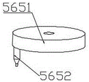
Preferably, as shown in fig. 5 and 6, the right material taking and mounting unit 56 includes an upper bearing seat 561, a lower bearing seat 563, a gear shaft 562, a transmission gear 564 and a chuck 565, the upper bearing seat 561 is fixed on the inner side of the upper portion of the material taking power frame 54, the lower bearing seat 563 is fixed on the inner side of the lower portion of the material taking power frame 54, two ends of the gear shaft 562 are respectively fixed in the upper bearing seat 561 and the lower bearing seat 563, the lower end portion of the gear shaft 562 downwardly passes through the lower bearing seat 563 and then extends to the outer side of the lower portion of the material taking power frame 54, the center of the chuck 565 is fixedly sleeved on the extending portion of the gear shaft 562 located on the outer side of the lower portion of the material taking power frame 54, the transmission gear 564 is fixedly sleeved on the middle position of the gear shaft 562 and is connected with, the chuck 565 comprises a disk-shaped disk seat 5651 and a clamping column 5652 vertically fixed on one side of the bottom of the disk seat 5651, the lower end part of the clamping column 5652 is a cone, the end part of the cone is of a cylinder structure, when the material taking stepping motor 53 rotates, the left material taking and installing unit 55 and the right material taking and installing unit 56 are driven to synchronously rotate, because the left material taking and installing unit 55 and the right material taking and installing unit 56 are arranged in a horizontal mirror image structure, the chuck 565 respectively rotates clockwise and anticlockwise, so that the clamping column 5652 rotates clockwise and anticlockwise, when the material taking stepping motor 53 rotates forwards, the transmission gear 564 of the left material taking and installing unit 55 and the right material taking and installing unit 56 is driven to synchronously rotate, and because the left material taking and installing unit 55 and the right material taking and installing unit 56 are arranged in the material taking power frame 54 in a horizontal mirror image structure, the chuck 565 of the left material taking and installing unit 55 and the right material taking And when the clamp spring needs to be installed, after the clamp spring is clamped on the automobile groove shaft, the material taking stepping motor 53 rotates reversely to enable the clamped clamp spring to recover the original state, and the clamp spring installation action is completed.
Preferably, as shown in fig. 7, the feeding mechanism 2 includes a feeding mounting frame 21, a feeding pushing assembly 22, a transverse sliding assembly 23 and a feeding moving plate 24, the feeding mounting frame 21 is fixedly disposed on the right side of the workbench 1, the feeding pushing assembly 22 is transversely fixed on the rear side of the upper portion of the feeding mounting frame 21, the transverse sliding assembly 23 is transversely fixed on the left position in the middle of the feeding mounting frame 21, the front side and the rear side of the bottom of the feeding moving plate 24 are respectively in sliding connection with the transverse sliding assembly 23, the feeding moving plate 24 is located under the feeding fastening assembly 3, the feeding pushing assembly 22 is a feeding pushing cylinder, the feeding pushing cylinder pushes the feeding moving plate 24 to move to under the material taking and downward pressing mounting mechanism 5, and since a stacked snap spring is disposed in the snap spring barrel 31, the snap spring located at the lowest layer freely falls on the feeding moving plate 24, because the distance between the lower end part of the clamp spring material cylinder 31 and the feeding and conveying plate 24 is slightly larger than the thickness of one clamp spring, when the feeding and pushing cylinder drives the feeding and conveying plate 24 to move leftwards, one clamp spring naturally falling onto the feeding and conveying plate 24 is synchronously moved leftwards to be positioned under the material taking and downward pressing installation mechanism 5.
Preferably, as shown in fig. 8, the feeding fastening assembly 3 comprises a clamp spring barrel 31, an upper sleeve fixing plate 32, a lower sleeve fixing plate 33, an upper fixing extension plate 34 and a lower fixing extension plate 35, the fixed ends of the upper fixed extension plate 34 and the lower fixed extension plate 35 are fixed in the middle of the right side plate of the support frame 7, and are distributed in parallel up and down, the other end of the upper fixed extension plate 34 is used for fixedly arranging the upper sleeve fixing plate 32, the other end of the lower fixed extension plate 35 is used for fixedly arranging the lower sleeve fixing plate 33, the circlip material cylinder 31 passes through the upper sleeve fixing plate 32 and the lower sleeve fixing plate 33 and then is positioned right above the feeding and conveying plate 24, and the interval between the lower end part and the feeding and conveying plate 24 is slightly larger than the thickness of a clamp spring, the clamp spring cylinder 31 is used for placing the clamp spring to be installed, and the clamp spring is in a longitudinal superposition state in the clamp spring cylinder 31.
Preferably, the press-fitting mold 6 comprises a press-fitting base 61 and a pneumatic pressing cylinder 62, the press-fitting base 61 is fixed on the front side of the workbench 1 and is located on the pneumatic press-fitting mold 6, the pneumatic pressing cylinder 62 is fixed on the side of the press-fitting mold 6, the press-fitting mold 6 is used for placing an automobile grooved shaft to be maintained, and the pneumatic pressing cylinder 62 is used for fastening and pressing the automobile grooved shaft placed on the press-fitting mold 6.
The working principle of the invention is as follows: the clamp spring to be installed is fully placed in the clamp spring cylinder 31 in advance, then the automobile grooved shaft to be installed with the clamp spring is placed on the press-fitting base 61, the automobile grooved shaft is firmly fixed through the pneumatic pressing cylinder 62, the feeding pushing assembly 22 drives the feeding conveying plate 24 to move leftwards so as to enable one clamp spring in the clamp spring cylinder 31 to be conveyed leftwards along the feeding conveying plate 24 to the position under the material taking lower-pressure installation mechanism 5, the driving assembly 42 works to enable the driving connecting plate 43 to slide downwards so as to drive the material taking lower-pressure installation mechanism 5 to move downwards, the material taking lower-pressure installation mechanism 5 slides downwards along the transverse sliding assembly 23 to the clamp spring on the feeding conveying plate 24, clamp posts 5652 of the left material taking unit and the right material taking unit are respectively embedded into two end holes of the clamp springs, the material taking stepping motor 53 works to rotate forwards so as to drive the chuck plates 565 of the left material taking unit and the right material, and then the clamping columns 5652 finish the actions of taking and opening the snap springs, the feeding pushing assembly 22 works to reset the feeding moving plate 24 to the right at the moment, then the pushing cylinder 51 is pressed downwards to work to drive the material taking power frame 54 to move downwards, and further the material taking mounting assembly is driven to move towards the automobile groove shaft placed on the press-fitting mold 6, and after the opened and clamped snap springs move downwards to the mounting position of the automobile groove shaft, the material taking stepping motor 53 rotates reversely, so that the clamped snap springs are restored to the original state, and the mounting action of mounting the snap springs on the automobile groove shaft is finished.
The technical features mentioned above are combined with each other to form various embodiments which are not listed above, and all of them are regarded as the scope of the present invention described in the specification; also, modifications and variations may be suggested to those skilled in the art in light of the above teachings, and it is intended to cover all such modifications and variations as fall within the true spirit and scope of the invention as defined by the appended claims.
Claims (9)
1. A maintenance and assembly device for a grooved shaft of an automobile is characterized by comprising a workbench, a feeding mechanism, a feeding fastening assembly, a taking driving mechanism, a taking downward-pressing installation mechanism, a pressing mold and a support frame, wherein the support frame is vertically fixed at the rear side of the workbench, the pressing mold is arranged at the front side of the workbench, the taking driving mechanism is vertically fixed at the top of the support frame and is downwards slidably connected to the front side of the support frame, the taking downward-pressing installation mechanism is vertically fixed at the lower end of the taking driving mechanism and is positioned right above the pressing mold, the feeding mechanism is arranged at the right side of the workbench, the feeding fastening assembly is vertically fixed at the right side surface of the support frame and is positioned right above the feeding mechanism, the support frame consists of a left side plate, a right side plate and a vertical plate, and the pressing mold is used for placing the grooved shaft to be assembled, the feeding mechanism is used for conveying clamp springs to be installed to be under the material taking and downward pressing installation mechanism, the material taking driving mechanism is used for driving the material taking and downward pressing installation mechanism to complete material taking actions of the clamp springs, the supporting frame is used for installing the material taking driving mechanism and the material taking and downward pressing installation mechanism, and the feeding fastening assembly is used for fixedly storing a clamp spring material barrel of the clamp springs.
2. The automobile grooved shaft maintenance and assembly equipment as claimed in claim 1, wherein the material taking driving mechanism comprises a driving mounting plate, a driving assembly, a driving connecting plate, a longitudinal sliding assembly and a material taking and pressing mounting plate, the rear end of the driving mounting plate is horizontally fixed at the top end of the supporting frame, the left and right sides of the front end of the driving mounting plate and the workbench are respectively fixedly supported by a supporting column, the driving assembly vertically penetrates through the front end of the driving mounting plate and is fixedly connected with the driving connecting plate downwards, the longitudinal sliding assembly is vertically fixed on the front surface of the vertical plate, the driving connecting plate is in an inverted L shape, the back part of the vertical surface of the driving connecting plate is slidably connected with the longitudinal sliding assembly, and the back part of the bottom surface of the driving connecting plate is fixedly connected with the lower end part of the driving assembly, get material and push down the horizontal fixed mounting in the inboard below in bottom surface of drive connecting plate, the drive mounting panel is used for the installation drive assembly, drive assembly is used for the drive connecting plate edge the longitudinal sliding subassembly is in the front longitudinal sliding of riser, and then the drive get the material and push down installation mechanism and vertically transfer, get the material and push down the mounting panel and be used for the installation get the material and push down installation mechanism.
3. The automobile grooved shaft maintenance and assembly equipment as claimed in claim 2, wherein the material taking and downward pressing installation mechanism comprises a downward pressing power assembly, a downward pressing connecting plate, a material taking power assembly, a material taking power frame and a material taking installation assembly, the downward pressing power assembly vertically penetrates through and is fixed on the bottom surface of the driving connecting plate and the material taking and downward pressing installation plate and is fixedly connected with the center of the downward pressing connecting plate, the left side and the right side of the downward pressing connecting plate are respectively and upwardly connected with the bottom surface of the driving connecting plate and the material taking and downward pressing installation plate through guide rods, the material taking power frame is fixedly connected below the downward pressing connecting plate through four upright posts, the material taking power assembly vertically penetrates through and is fixed on the upper portion of the material taking power frame and extends downward into the material taking power frame, and the material taking installation assembly is vertically and fixedly installed in the material taking power frame and extends downward, and is meshed and connected with the output end of the material taking power assembly through a gear.
4. The automobile grooved shaft maintenance assembly equipment as claimed in claim 3, wherein the downward-pressing power assembly is a downward-pressing pushing cylinder vertically penetrating and fixed on the bottom surface of the driving connecting plate and the material taking downward-pressing mounting plate, an output end of the downward-pressing pushing cylinder is fixedly connected with the center of the downward-pressing connecting plate downward and used for driving the downward-pressing connecting plate to move downwards so as to drive the material taking power frame and the material taking mounting assembly to move downwards, the material taking power assembly is a material taking stepping motor, and an output end of the material taking stepping motor is connected with the material taking mounting assembly downward through gear engagement.
5. The automobile grooved shaft maintenance assembly equipment as claimed in claim 4, wherein the material taking and mounting assembly comprises a left material taking and mounting unit and a right material taking and mounting unit, the left material taking and mounting unit and the right material taking and mounting unit are vertically and fixedly mounted in the material taking power frame and extend downwards, the left material taking and mounting unit and the right material taking and mounting unit are arranged in the material taking power frame in a horizontal mirror image structure, and transmission parts between the left material taking and mounting unit and the right material taking and mounting unit are connected through gear engagement.
6. The automobile grooved shaft maintenance assembly equipment as claimed in claim 5, wherein the right material taking mounting unit comprises an upper bearing seat, a lower bearing seat, a gear shaft, a transmission gear and a chuck plate, the upper bearing seat is fixed on the inner side of the upper part of the material taking power frame, the lower bearing seat is fixed on the inner side of the lower part of the material taking power frame, two ends of the gear shaft are respectively fixed in the upper bearing seat and the lower bearing seat, the lower end part of the gear shaft downwards penetrates through the lower bearing seat and then extends to the outer side of the lower part of the material taking power frame, the center of the chuck plate is fixedly sleeved on a gear shaft extension part positioned on the outer side of the lower part of the material taking power frame, the transmission gear is fixedly sleeved at the middle position of the gear shaft and is meshed with the output, the (holding) chuck is including the disk seat that is the disc and vertical being fixed in the double-layered post of disk seat bottom one side, the lower tip of pressing from both sides the post is the cone, and the tip of cone is the cylinder structure, and when getting material step motor and rotate, and then drive left side is got material installation unit and right side and get the synchronous rotation of material installation unit, because the left side is got material installation unit and right side and is got material installation unit and be horizontal mirror image structure setting, consequently the (holding) chuck is clockwise and anticlockwise rotation respectively, and then makes the double-layered post do clockwise.
7. The automobile grooved shaft maintenance assembly equipment as claimed in claim 1, wherein the feeding mechanism includes a feeding mounting frame, a feeding pushing assembly, a lateral sliding assembly and a feeding moving plate, the feeding mounting frame is fixedly arranged on the right side of the workbench, the feeding pushing assembly is laterally fixed on the rear side of the upper portion of the feeding mounting frame, the lateral sliding assembly is laterally fixed on the left position in the middle of the feeding mounting frame, the front side and the rear side of the bottom of the feeding moving plate are respectively in sliding connection with the lateral sliding assembly, and the feeding moving plate is located under the feeding fastening assembly.
8. The automobile grooved shaft maintenance assembly equipment as claimed in claim 7, wherein the feeding fastening assembly comprises a clamp spring material cylinder, an upper sleeve fixing plate, a lower sleeve fixing plate, an upper fixed extension plate and a lower fixed extension plate, fixed ends of the upper fixed extension plate and the lower fixed extension plate are fixed in the middle of a right side plate of the support frame and are distributed in a vertical parallel manner, the other end of the upper fixed extension plate is used for fixedly arranging the upper sleeve fixing plate, the other end of the lower fixed extension plate is used for fixedly arranging the lower sleeve fixing plate, the clamp spring material cylinder penetrates through the upper sleeve fixing plate and the lower sleeve fixing plate and then is located right above the feeding moving plate, and the interval between the lower end of the clamp spring material cylinder and the feeding moving plate is slightly larger than the thickness of one clamp spring.
9. The automobile grooved shaft maintenance and assembly equipment as claimed in claim 1, wherein the press-fitting mold comprises a press-fitting base and a pneumatic press-fitting cylinder, the press-fitting base is fixed to the front side of the workbench and located on the pneumatic press-fitting mold, the pneumatic press-fitting cylinder is fixed to the side of the press-fitting mold, the press-fitting mold is used for placing the automobile grooved shaft to be maintained, and the pneumatic press-fitting cylinder is used for tightly pressing the automobile grooved shaft placed on the press-fitting mold.
Priority Applications (1)
| Application Number | Priority Date | Filing Date | Title |
|---|---|---|---|
| CN202010708812.7A CN111761334A (en) | 2020-07-22 | 2020-07-22 | Be used for car groove axle maintenance rigging equipment |
Applications Claiming Priority (1)
| Application Number | Priority Date | Filing Date | Title |
|---|---|---|---|
| CN202010708812.7A CN111761334A (en) | 2020-07-22 | 2020-07-22 | Be used for car groove axle maintenance rigging equipment |
Publications (1)
| Publication Number | Publication Date |
|---|---|
| CN111761334A true CN111761334A (en) | 2020-10-13 |
Family
ID=72727389
Family Applications (1)
| Application Number | Title | Priority Date | Filing Date |
|---|---|---|---|
| CN202010708812.7A Pending CN111761334A (en) | 2020-07-22 | 2020-07-22 | Be used for car groove axle maintenance rigging equipment |
Country Status (1)
| Country | Link |
|---|---|
| CN (1) | CN111761334A (en) |
Citations (14)
| Publication number | Priority date | Publication date | Assignee | Title |
|---|---|---|---|---|
| JPH02145224A (en) * | 1988-11-21 | 1990-06-04 | Nippondenso Co Ltd | Automatic thread fastening device |
| US20090158809A1 (en) * | 2007-12-25 | 2009-06-25 | Takashi Murayama | Hog ring fastening device |
| CN104476179A (en) * | 2014-12-01 | 2015-04-01 | 昂华(上海)自动化工程股份有限公司 | Automatic assembling mechanism for spring collar of differential mechanism |
| CN204524726U (en) * | 2015-04-14 | 2015-08-05 | 吉林大学 | Jump ring automatic mounting machine in a kind of |
| CN206373575U (en) * | 2017-01-13 | 2017-08-04 | 重庆建设车用空调器有限责任公司 | A kind of material stock and feed device for extending out formula jump ring automatic assembling |
| CN107932380A (en) * | 2017-12-25 | 2018-04-20 | 南京工程学院 | A kind of C-shaped is preced with spring Automated assembly fixture |
| CN108247326A (en) * | 2016-12-28 | 2018-07-06 | 上海新宇箴诚电控科技有限公司 | The device that a kind of c-type clamp spring is installed automatically |
| CN208083831U (en) * | 2017-11-26 | 2018-11-13 | 穆林冉 | A kind of valve assembling mechanism based on CCD camera positioning |
| CN110091153A (en) * | 2019-03-04 | 2019-08-06 | 江苏龙城精锻有限公司 | A kind of circlip automatic press mounting equipment |
| CN209206892U (en) * | 2018-12-20 | 2019-08-06 | 常州市华创电子设备有限公司 | A kind of axis assembling device for snap spring |
| CN110253251A (en) * | 2019-06-28 | 2019-09-20 | 无锡双益精密机械有限公司 | A kind of automatic press-in device of lining ring |
| CN110788607A (en) * | 2019-11-13 | 2020-02-14 | 含山县祥瑞运输有限公司 | Continuous nut feeding device for machining automobile parts |
| CN210849101U (en) * | 2019-08-22 | 2020-06-26 | 昆山睿力得自动化技术有限公司 | Assembly quality of jump ring and axle |
| CN211028841U (en) * | 2019-11-11 | 2020-07-17 | 苏州卡杰斯机电设备有限公司 | Automatic clamp spring assembling machine |
-
2020
- 2020-07-22 CN CN202010708812.7A patent/CN111761334A/en active Pending
Patent Citations (14)
| Publication number | Priority date | Publication date | Assignee | Title |
|---|---|---|---|---|
| JPH02145224A (en) * | 1988-11-21 | 1990-06-04 | Nippondenso Co Ltd | Automatic thread fastening device |
| US20090158809A1 (en) * | 2007-12-25 | 2009-06-25 | Takashi Murayama | Hog ring fastening device |
| CN104476179A (en) * | 2014-12-01 | 2015-04-01 | 昂华(上海)自动化工程股份有限公司 | Automatic assembling mechanism for spring collar of differential mechanism |
| CN204524726U (en) * | 2015-04-14 | 2015-08-05 | 吉林大学 | Jump ring automatic mounting machine in a kind of |
| CN108247326A (en) * | 2016-12-28 | 2018-07-06 | 上海新宇箴诚电控科技有限公司 | The device that a kind of c-type clamp spring is installed automatically |
| CN206373575U (en) * | 2017-01-13 | 2017-08-04 | 重庆建设车用空调器有限责任公司 | A kind of material stock and feed device for extending out formula jump ring automatic assembling |
| CN208083831U (en) * | 2017-11-26 | 2018-11-13 | 穆林冉 | A kind of valve assembling mechanism based on CCD camera positioning |
| CN107932380A (en) * | 2017-12-25 | 2018-04-20 | 南京工程学院 | A kind of C-shaped is preced with spring Automated assembly fixture |
| CN209206892U (en) * | 2018-12-20 | 2019-08-06 | 常州市华创电子设备有限公司 | A kind of axis assembling device for snap spring |
| CN110091153A (en) * | 2019-03-04 | 2019-08-06 | 江苏龙城精锻有限公司 | A kind of circlip automatic press mounting equipment |
| CN110253251A (en) * | 2019-06-28 | 2019-09-20 | 无锡双益精密机械有限公司 | A kind of automatic press-in device of lining ring |
| CN210849101U (en) * | 2019-08-22 | 2020-06-26 | 昆山睿力得自动化技术有限公司 | Assembly quality of jump ring and axle |
| CN211028841U (en) * | 2019-11-11 | 2020-07-17 | 苏州卡杰斯机电设备有限公司 | Automatic clamp spring assembling machine |
| CN110788607A (en) * | 2019-11-13 | 2020-02-14 | 含山县祥瑞运输有限公司 | Continuous nut feeding device for machining automobile parts |
Non-Patent Citations (1)
| Title |
|---|
| 云与影的交织: "孔卡卡簧自动装配机", 《沐风网》 * |
Similar Documents
| Publication | Publication Date | Title |
|---|---|---|
| CN210937996U (en) | Automatic change animal doctor needle kludge | |
| CN110315309B (en) | Automatic rubber pad assembling equipment and assembling method thereof | |
| CN215035216U (en) | Slide rail assembly machine | |
| CN112355632A (en) | Gear shaft assembly automatic assembly equipment | |
| CN111761334A (en) | Be used for car groove axle maintenance rigging equipment | |
| CN210879411U (en) | Automatic D head and triangular pawl feeding and assembling device of ratchet wrench | |
| CN108555596B (en) | Automatic assembling device for ship steering wheel fast wheel | |
| CN114291341B (en) | Automobile sun visor lens packaging machine and working method thereof | |
| CN113059602B (en) | Gasket auxiliary trimming device for manufacturing high-end equipment | |
| CN114148582A (en) | Coil full-automatic bagging robot equipment and bagging method | |
| CN117020539B (en) | Convenient assembly device based on intelligent welding | |
| CN220882116U (en) | Adjustable toy car assembly jig | |
| CN113305538B (en) | Processing mechanism of aluminum electrolytic capacitor | |
| CN220387805U (en) | Double riveting machine for riveting automobile components | |
| CN211305458U (en) | Clamp spring feeding mechanism of hub assembling device of electric vehicle | |
| CN219601705U (en) | Film pasting jig for optical fiber array substrate | |
| CN112682663B (en) | Woodworking machine base increases device for construction | |
| CN219325544U (en) | Pasting device suitable for single-sided adhesive cushion pad | |
| CN219822841U (en) | Feeding mechanism | |
| CN211768468U (en) | Movable glued membrane automatic feed structure | |
| CN116682746B (en) | Bonding wire workbench of chip multi-station welding machine and application method thereof | |
| CN220196831U (en) | Automatic jump ring assembly device | |
| CN214640038U (en) | Fixing clamp for rivet pulling of nut of bottom plate cross beam | |
| CN219436817U (en) | Motor rotor bearing assembly dispensing all-in-one machine | |
| CN214977475U (en) | Automatic forging device of annular auto-parts |
Legal Events
| Date | Code | Title | Description |
|---|---|---|---|
| PB01 | Publication | ||
| PB01 | Publication | ||
| SE01 | Entry into force of request for substantive examination | ||
| SE01 | Entry into force of request for substantive examination | ||
| RJ01 | Rejection of invention patent application after publication | ||
| RJ01 | Rejection of invention patent application after publication |
Application publication date: 20201013 |