CN111749119A - Speed locking mild steel damper and large-span bridge comprising same - Google Patents
Speed locking mild steel damper and large-span bridge comprising same Download PDFInfo
- Publication number
- CN111749119A CN111749119A CN202010651092.5A CN202010651092A CN111749119A CN 111749119 A CN111749119 A CN 111749119A CN 202010651092 A CN202010651092 A CN 202010651092A CN 111749119 A CN111749119 A CN 111749119A
- Authority
- CN
- China
- Prior art keywords
- mild steel
- speed
- damping
- steel damper
- top plate
- Prior art date
- Legal status (The legal status is an assumption and is not a legal conclusion. Google has not performed a legal analysis and makes no representation as to the accuracy of the status listed.)
- Granted
Links
Images


Classifications
-
- E—FIXED CONSTRUCTIONS
- E01—CONSTRUCTION OF ROADS, RAILWAYS, OR BRIDGES
- E01D—CONSTRUCTION OF BRIDGES, ELEVATED ROADWAYS OR VIADUCTS; ASSEMBLY OF BRIDGES
- E01D19/00—Structural or constructional details of bridges
Abstract
The embodiment of the application discloses a speed locking mild steel damper and a large-span bridge comprising the same, so as to meet the longitudinal shock absorption requirements of the bridge under the action of different dynamic loads. To this end, an aspect of the embodiment of the present application provides a velocity lock mild steel damper, including a horizontally disposed velocity lock and a damping tenon assembly, where the damping tenon assembly includes a base, a plurality of damping tenons, and a top plate; the damping tenons are vertically and fixedly arranged at the top of the base, a spherical force transmission head is fixedly connected to the top end of each damping tenon, the spherical force transmission heads are installed in an installation cavity in the bottom of the top plate in a matched mode, and a piston rod of the speed locker is fixedly connected with the side portion of the top plate.
Description
Technical Field
The invention belongs to the technical field of shock absorption, and particularly relates to a speed locking mild steel damper and a large-span bridge comprising the same.
Background
At present, the longitudinal shock absorption of the large-span bridge is most commonly used by a large-tonnage viscous damper. Although the viscous damper can effectively absorb shock, the large-tonnage viscous damper is expensive, can fail under the action of large load, and is extremely complex to maintain and replace. The soft steel damper is used independently, and although the capacity of resisting a large earthquake is remarkable, the energy consumption can not be realized when the soft steel damper works under the action of small load or temperature due to the characteristic that the soft steel damper must be yielded to carry out displacement hysteresis energy consumption.
Disclosure of Invention
The present application is directed to solving at least one of the problems in the prior art. Therefore, one of the objectives of the embodiments of the present invention is to provide a speed-locking mild steel damper capable of simultaneously responding to the longitudinal damping requirements of a bridge under different dynamic loads, and a long-span bridge comprising the same.
To this end, an aspect of the embodiment of the present application provides a velocity lock mild steel damper, including a horizontally disposed velocity lock and a damping tenon assembly, where the damping tenon assembly includes a base, a plurality of damping tenons, and a top plate;
the damping tenons are vertically and fixedly arranged at the top of the base, a spherical force transmission head is fixedly connected to the top end of each damping tenon, the spherical force transmission heads are installed in an installation cavity in the bottom of the top plate in a matched mode, and a piston rod of the speed locker is fixedly connected with the side portion of the top plate.
In some embodiments, an extension of the axis of the piston rod passes through the center of the sphere of the spherical force transfer head.
In some embodiments, a plurality of the shock absorbing tenons are distributed in an array on the base.
In some embodiments, a plurality of the shock absorbing tenons are distributed in a rectangular array on the base.
In some embodiments, the inner wall of the mounting cavity is provided with a polytetrafluoroethylene coating.
In some embodiments, a first connecting plate is arranged at the side part of the top plate, and a second connecting plate is hinged to the side part of the piston rod;
the first connecting plate and the second connecting plate are connected through a bolt assembly in a fastening mode.
In some embodiments, the bottom of the top plate is further provided with a limit stop for preventing the spherical force transmission head from falling out of the mounting cavity.
On the other hand of the embodiment of this application provides the long-span bridge that contains above-mentioned embodiment speed locking mild steel attenuator, the speed locking ware is kept away from the one end of shock attenuation tenon subassembly with the girder connection of bridge, the base is fixed to be set up the top of the pier of bridge.
Compared with the prior art, at least one embodiment of the application has the following beneficial effects:
under the normal working condition of the bridge, the movement speed of the piston rod is smaller than the locking speed of the speed lock locker, the speed lock locker can work normally, so that the piston rod can move freely without limitation under the action of various small loads (such as wind, vehicle loads and the like) and temperature, when large load conditions such as an earthquake and the like are met, the movement speed of the piston rod is larger than the locking speed of the speed lock locker, the speed lock locker is locked, the piston rod is equivalent to a rigid connecting rod, the damping tenon component consumes energy when working, large damping force and large displacement are provided, various large power loads are effectively resisted, and the speed locking soft steel damper can meet the longitudinal damping requirements of the bridge under the action of different power loads.
Drawings
In order to more clearly illustrate the technical solutions in the embodiments of the present invention, the drawings needed to be used in the description of the embodiments will be briefly introduced below, and it is obvious that the drawings in the following description are only some embodiments of the present invention, and it is obvious for those skilled in the art to obtain other drawings based on these drawings without creative efforts.
FIG. 1 is a schematic structural diagram of a bridge including a velocity-locking mild steel damper provided in an embodiment of the present application;
FIG. 2 is a schematic side view of a bridge including a velocity-locking mild steel damper provided by an embodiment of the present application;
FIG. 3 is a schematic partial view of a velocity lock mild steel damper provided in an embodiment of the present application.
Detailed Description
The technical solutions in the embodiments of the present invention will be clearly and completely described below with reference to the drawings in the embodiments of the present invention, and it is obvious that the described embodiments are only a part of the embodiments of the present invention, and not all of the embodiments. All other embodiments, which can be derived by a person skilled in the art from the embodiments given herein without making any creative effort, shall fall within the protection scope of the present invention.
The embodiment of the application provides a speed locking mild steel damper and a large-span bridge comprising the same, so that the longitudinal shock absorption requirements of the bridge under the action of different dynamic loads are met.
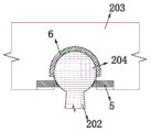
Referring to fig. 1 to 3, a speed-locking mild steel damper provided by an aspect of an embodiment of the present application includes a horizontally disposed speed locker 1 and a damping tenon assembly 2, where the damping tenon assembly 2 includes a base 201, a plurality of damping tenons 202, and a top plate 203; wherein the content of the first and second substances,
the damping tenons 202 are vertically and fixedly arranged at the top of the base 201, a spherical force transmission head 204 is fixedly connected to the top end of each damping tenon 202, the spherical force transmission head 204 is installed in the installation cavity 4 at the bottom of the top plate 203 in a matching mode, and the piston rod 101 of the speed locker is fixedly connected with the side portion of the top plate 203.
In the embodiment of the application, when the load borne by the speed lock locker is small, the moving speed of the piston rod 101 is smaller than the locking speed of the speed lock locker, the speed lock 1 can work normally, so that the speed lock can move freely without limitation under the action of various small loads (such as wind, vehicle load and the like) and temperature, when meeting large load conditions such as an earthquake and the like, the moving speed of the piston rod 101 is larger than the locking speed of the speed lock locker, the speed lock 1 is locked, which is equivalent to a rigid connecting rod, the force of the piston rod 101 is transmitted to the damping tenon from the top plate 203 through the spherical force transmission head 204, the damping tenon deforms to begin to work and consume energy, and large damping force and large displacement are provided, so that various large dynamic loads are effectively resisted, and the speed lock soft steel damper can meet the longitudinal damping requirements of bridges under the action of different dynamic loads.
Referring to fig. 1-3, in some possible embodiments, the extension of the axis of the piston rod 101 passes through the center of the sphere of the spherical force transfer head 204. In the embodiment of the present application, since the output centerline of the piston rod 101 passes through the center of the spherical head 204, only the horizontal pushing force or pulling force is transmitted to the top plate 203, the vertical force is not transmitted, and the additional bending moment is not caused by the additional moment arm.
It should be noted that, in practical design, the damping tenons are distributed on the base 201 in a rectangular array, but may also be distributed in a circumferential array.
Specifically, a threaded mounting hole is formed in the top of the base 201, an external thread matched with the threaded mounting hole is formed in the bottom of the damping tenon 202, and the damping tenon 202 is screwed and fixed in the threaded mounting hole. In the embodiment of the application, the damping tenon 202 is in threaded fastening connection with the base 201, and the damping tenon 202 is convenient to replace.
In some possible embodiments, a limit stop 5 is further disposed at the bottom of the top plate 203 to prevent the spherical force transmission head 204 from coming out of the mounting cavity 4, specifically, the limit stop 5 is welded and fixed in a stop groove beside the mounting cavity 4, the limit stop 5 is not in contact with the spherical force transmission head 204, so that the spherical force transmission head 204 can rotate freely in the mounting cavity 4 under normal action without being stressed. Under the action of a vertical earthquake or other loads which cause the vertical relative displacement between the main beam and the pier 11, the limit stop 5 has a limiting effect and prevents the spherical force transmission head 204 from being separated from the installation cavity 4.
Note: the anchor plate 10 is not a main beam abutment but is an anchor plate integral with the speed lock and is directly connected to the anchor of the main beam, so that the anchor plate 10 is part of the speed lock and cannot be called a bridge abutment.
It will be appreciated that the shock absorbing tenons may be made of mild steel, since mild steel is a steel material with a significant yield point, and has a high initial stiffness and a low post-yield stiffness. The soft steel component is elastic before yielding, and can consume energy through hysteresis after yielding.
In practical application, the inner wall of the installation cavity 4 can be coated with the polytetrafluoroethylene coating 6, so that the aim of low friction force is fulfilled. In addition, a first connecting plate 7 may be disposed at a side portion of the top plate 203, and a second connecting plate 8 may be hingedly connected to a side portion of the piston rod 101, and the first connecting plate 7 and the second connecting plate 8 are fastened by a bolt assembly 9.
Referring to fig. 1 and 2, another aspect of the embodiments of the present application provides a large-span bridge including a velocity-locking mild steel damper according to the above-described embodiments, which is installed between a girder 10 and an abutment 11 of the bridge in a longitudinal direction of the bridge.
Specifically, the speed locking mild steel damper comprises a speed locking device 1 and a damping tenon assembly 2 which are horizontally arranged, wherein the damping tenon assembly 2 comprises a base 201, a plurality of damping tenons 202 and a top plate 203; wherein, the end of the speed locker 1 far away from the damping tenon component 2 is hinged with the girder 10 of the bridge, and the base 201 is tightly installed on the top of the pier 11 of the bridge through the bolt 12.
Specifically, a plurality of shock absorption tenons are vertically and fixedly arranged at the top of the base 201, a spherical force transmission head 204 is fixedly connected to the top end of each shock absorption tenon, the spherical force transmission heads 204 are installed in the installation cavity 4 in the bottom of the top plate 203 in a matched mode, the piston rod 101 of the speed locker is fixedly connected with the side portion of the top plate 203, and a limit stop 5 for preventing the spherical force transmission heads 204 from being separated from the installation cavity 4 is further arranged at the bottom of the top plate 203.
The large-span bridge that contains above-mentioned embodiment speed locking mild steel attenuator that this application embodiment provided, under the normal use condition, the bridge receives the effect of vehicle, wind and temperature load, and these loads can make the bridge girder vertically take place less displacement. The speed lock 1 now works normally and moves freely. The damping tongue arrangement 2 is now subjected to a lower force, has not yet reached its yield point, and is in an elastic state, corresponding to a fixed end. Under the action of an earthquake, the movement speed of the piston rod 101 is greater than the locking speed, the speed locker 1 is locked and is equivalent to a rigid connecting rod, and the top plate 203 of the damping tenon assembly 2 is driven to move together through the connecting plate. The roof 203 is equipped with installation cavity 4, and the spherical type power transmission head 204 of shock attenuation tenon inlays in installation cavity 4, therefore power and displacement from roof 203 through spherical type power transmission head 204 transmit the shock attenuation tenon on, the shock attenuation tenon takes place to deform, until surrender. After the damping tenon yields, the displacement of the bridge continues to increase, so that the deformation of the damping tenon is further increased, and the plasticity degree is higher and higher. Because the earthquake action is irregular, the bridge can generate reverse displacement in opposite directions to drive the damping tenon to repeatedly deform, thereby dissipating energy in a hysteretic manner.
In some possible embodiments, the extension line of the axis of the piston rod 101 passes through the center of the spherical head 204, and in the present embodiment, since the output centerline of the piston rod 101 passes through the center of the spherical head 204, only horizontal pushing or pulling force is transmitted to the top plate 203, vertical force is not transmitted, and additional bending moment is not caused by additional moment arm.
In some possible embodiments, a limit stop 5 is further disposed at the bottom of the top plate 203 to prevent the spherical force transmission head 204 from coming out of the mounting cavity 4, specifically, the limit stop 5 is welded and fixed in a stop groove beside the mounting cavity 4, the limit stop 5 is not in contact with the spherical force transmission head 204, so that the spherical force transmission head 204 can rotate freely in the mounting cavity 4 under normal action without being stressed. Under the action of a vertical earthquake or other loads which cause vertical relative displacement between the bridge and the pier 11, the limit stop 5 has a limiting effect and prevents the spherical force transmission head 204 from being separated from the installation cavity 4.
The above examples are merely illustrative for clearly illustrating the present invention and are not intended to limit the embodiments. Other variations and modifications will be apparent to persons skilled in the art in light of the above description. Nor is it intended to be exhaustive of all embodiments. And obvious variations or modifications of the invention may be made without departing from the scope of the invention.
Claims (10)
1. Speed locking mild steel attenuator, its characterized in that: the damping tenon component comprises a base, a plurality of damping tenons and a top plate;
the damping tenons are vertically and fixedly arranged at the top of the base, a spherical force transmission head is fixedly connected to the top end of each damping tenon, the spherical force transmission heads are installed in an installation cavity in the bottom of the top plate in a matched mode, and a piston rod of the speed locker is fixedly connected with the side portion of the top plate.
2. The speed locking mild steel damper according to claim 1, wherein: the extension line of the axis of the piston rod passes through the spherical center of the spherical force transmission head.
3. The speed locking mild steel damper according to claim 1 or 2, characterized in that: the shock absorption tenons are distributed on the base in a rectangular array mode.
4. The speed locking mild steel damper according to claim 3, wherein: the shock absorption tenon is in threaded fastening connection with the base.
5. The speed locking mild steel damper according to claim 1 or 2, characterized in that: and a polytetrafluoroethylene coating is arranged on the inner wall of the mounting cavity.
6. The speed locking mild steel damper according to claim 1 or 2, characterized in that: a first connecting plate is arranged on the side of the top plate, and a second connecting plate is hinged to the side of the piston rod;
the first connecting plate and the second connecting plate are connected through a bolt assembly in a fastening mode.
7. The speed locking mild steel damper according to claim 1 or 2, characterized in that: and the bottom of the top plate is also provided with a limit stop block for preventing the spherical force transmission head from being separated from the mounting cavity.
8. The speed locking mild steel damper according to claim 1 or 2, characterized in that: the damping tenon is made of mild steel.
9. A large span bridge comprising a speed locking mild steel damper according to any one of claims 1 to 8, wherein: one end of the speed locker, which is far away from the damping tenon component, is connected with the main beam of the bridge, and the base is fixedly arranged at the top of the pier of the bridge.
10. The large-span bridge comprising the large-span bridge of claim 9, wherein: the speed locker is hinged to the main beam.
Priority Applications (1)
| Application Number | Priority Date | Filing Date | Title |
|---|---|---|---|
| CN202010651092.5A CN111749119B (en) | 2020-07-08 | 2020-07-08 | Speed locking mild steel damper and large-span bridge comprising same |
Applications Claiming Priority (1)
| Application Number | Priority Date | Filing Date | Title |
|---|---|---|---|
| CN202010651092.5A CN111749119B (en) | 2020-07-08 | 2020-07-08 | Speed locking mild steel damper and large-span bridge comprising same |
Publications (2)
| Publication Number | Publication Date |
|---|---|
| CN111749119A true CN111749119A (en) | 2020-10-09 |
| CN111749119B CN111749119B (en) | 2021-08-10 |
Family
ID=72709886
Family Applications (1)
| Application Number | Title | Priority Date | Filing Date |
|---|---|---|---|
| CN202010651092.5A Active CN111749119B (en) | 2020-07-08 | 2020-07-08 | Speed locking mild steel damper and large-span bridge comprising same |
Country Status (1)
| Country | Link |
|---|---|
| CN (1) | CN111749119B (en) |
Cited By (2)
| Publication number | Priority date | Publication date | Assignee | Title |
|---|---|---|---|---|
| CN113502734A (en) * | 2021-07-21 | 2021-10-15 | 河北工业大学 | Speed locking type three-order yield damper capable of achieving self-resetting |
| CN115948976A (en) * | 2022-12-19 | 2023-04-11 | 中交公路规划设计院有限公司 | Longitudinal combination toughness constraint system and method for large-span suspension bridge |
Citations (12)
| Publication number | Priority date | Publication date | Assignee | Title |
|---|---|---|---|---|
| KR100646329B1 (en) * | 2005-06-02 | 2006-11-23 | 주식회사 에스코테크놀로지 | Earthquake-resistant device of bridge |
| CN101793004A (en) * | 2010-02-26 | 2010-08-04 | 成都市新筑路桥机械股份有限公司 | Seismic isolation and reduction structure of bridge |
| CN101892624A (en) * | 2010-07-16 | 2010-11-24 | 成都市新筑路桥机械股份有限公司 | Bridge shock absorption and isolation structure |
| CN201778280U (en) * | 2010-09-20 | 2011-03-30 | 成都市新筑路桥机械股份有限公司 | Fixing shock absorption buckling tenon for bridges |
| CN201972240U (en) * | 2010-12-28 | 2011-09-14 | 陈云 | Self-resetting swinging shock-isolation support |
| CN102953327A (en) * | 2012-11-15 | 2013-03-06 | 同济大学 | Lateral shock absorption damper suitable for bridge structure |
| CN203200648U (en) * | 2013-03-20 | 2013-09-18 | 株洲时代新材料科技股份有限公司 | Beam falling resistant device with energy dissipation function and shock absorption function in longitudinal bridge direction and vertical direction |
| CN206015506U (en) * | 2016-08-05 | 2017-03-15 | 武汉艾尔格桥梁新技术开发有限公司 | Two-way big displacement speed locking device |
| CN206553915U (en) * | 2016-11-04 | 2017-10-13 | 济南大学 | Soft damping steel vibration absorption and isolation support |
| CN207715914U (en) * | 2017-10-30 | 2018-08-10 | 福州鹏飞制冷设备有限公司 | A kind of spherical shape aseismatic bearing |
| CN109024708A (en) * | 2018-07-09 | 2018-12-18 | 天津城建大学 | A kind of isolation mounting for building and subway upper cover vertical vibration isolation wave building structure |
| CN109098306A (en) * | 2018-09-28 | 2018-12-28 | 福州大学 | A kind of friction-mild steel composite buffer and assembly method |
-
2020
- 2020-07-08 CN CN202010651092.5A patent/CN111749119B/en active Active
Patent Citations (12)
| Publication number | Priority date | Publication date | Assignee | Title |
|---|---|---|---|---|
| KR100646329B1 (en) * | 2005-06-02 | 2006-11-23 | 주식회사 에스코테크놀로지 | Earthquake-resistant device of bridge |
| CN101793004A (en) * | 2010-02-26 | 2010-08-04 | 成都市新筑路桥机械股份有限公司 | Seismic isolation and reduction structure of bridge |
| CN101892624A (en) * | 2010-07-16 | 2010-11-24 | 成都市新筑路桥机械股份有限公司 | Bridge shock absorption and isolation structure |
| CN201778280U (en) * | 2010-09-20 | 2011-03-30 | 成都市新筑路桥机械股份有限公司 | Fixing shock absorption buckling tenon for bridges |
| CN201972240U (en) * | 2010-12-28 | 2011-09-14 | 陈云 | Self-resetting swinging shock-isolation support |
| CN102953327A (en) * | 2012-11-15 | 2013-03-06 | 同济大学 | Lateral shock absorption damper suitable for bridge structure |
| CN203200648U (en) * | 2013-03-20 | 2013-09-18 | 株洲时代新材料科技股份有限公司 | Beam falling resistant device with energy dissipation function and shock absorption function in longitudinal bridge direction and vertical direction |
| CN206015506U (en) * | 2016-08-05 | 2017-03-15 | 武汉艾尔格桥梁新技术开发有限公司 | Two-way big displacement speed locking device |
| CN206553915U (en) * | 2016-11-04 | 2017-10-13 | 济南大学 | Soft damping steel vibration absorption and isolation support |
| CN207715914U (en) * | 2017-10-30 | 2018-08-10 | 福州鹏飞制冷设备有限公司 | A kind of spherical shape aseismatic bearing |
| CN109024708A (en) * | 2018-07-09 | 2018-12-18 | 天津城建大学 | A kind of isolation mounting for building and subway upper cover vertical vibration isolation wave building structure |
| CN109098306A (en) * | 2018-09-28 | 2018-12-28 | 福州大学 | A kind of friction-mild steel composite buffer and assembly method |
Cited By (2)
| Publication number | Priority date | Publication date | Assignee | Title |
|---|---|---|---|---|
| CN113502734A (en) * | 2021-07-21 | 2021-10-15 | 河北工业大学 | Speed locking type three-order yield damper capable of achieving self-resetting |
| CN115948976A (en) * | 2022-12-19 | 2023-04-11 | 中交公路规划设计院有限公司 | Longitudinal combination toughness constraint system and method for large-span suspension bridge |
Also Published As
| Publication number | Publication date |
|---|---|
| CN111749119B (en) | 2021-08-10 |
Similar Documents
| Publication | Publication Date | Title |
|---|---|---|
| CN111749119B (en) | Speed locking mild steel damper and large-span bridge comprising same | |
| CN102720124B (en) | Fluid viscous damper with working switch | |
| CN105735115B (en) | Connecting shock absorption device for continuous girder bridge zone control | |
| CN113585849B (en) | Two-stage friction damper | |
| CN112081263A (en) | Buckling restrained brace outrigger truss and combined type shock attenuation high-rise structure system | |
| CN113152730A (en) | Assembled composite energy dissipation shear wall | |
| CN206256370U (en) | Firm arm speed lockup's vibration absorption and isolation support such as one kind | |
| CN111827098A (en) | Trigger type limited negative stiffness high-strength spring damping support | |
| CN116446266A (en) | Beam falling prevention damping device and beam falling prevention damping system | |
| CN113818338B (en) | Bridge, horizontal bidirectional vibration damping/vibrating support thereof and vibration damping/vibrating method | |
| CN215104596U (en) | Cable type graded energy absorption type beam falling prevention device | |
| CN202755295U (en) | Liquid viscous damper with operating switch | |
| CN210369407U (en) | Building shock attenuation power consumption structure | |
| CN215406706U (en) | Assembled composite energy dissipation shear wall | |
| CN111827502B (en) | High-efficient energy dissipation shock attenuation engineering structure system | |
| CN210290579U (en) | Prestressed damping spring | |
| CN114277952A (en) | Composite damper | |
| CN109695200B (en) | Generalized acceleration mass damper system for transverse bridge direction and torsional vibration reduction of suspension bridge | |
| CN209368666U (en) | A kind of metal damp type girder falling vibration absorption and isolation support | |
| CN113622535A (en) | Self-resetting damper based on zinc-aluminum alloy and manufacturing method thereof | |
| CN112681520A (en) | Wood structure building beam column shock absorber | |
| CN111851270A (en) | Vertical cambered surface metal damper | |
| CN214574816U (en) | Metal energy dissipation damper | |
| CN217460231U (en) | Multifunctional energy consumption device | |
| CN219586548U (en) | Damping buffering friction shock insulation support |
Legal Events
| Date | Code | Title | Description |
|---|---|---|---|
| PB01 | Publication | ||
| PB01 | Publication | ||
| SE01 | Entry into force of request for substantive examination | ||
| SE01 | Entry into force of request for substantive examination | ||
| GR01 | Patent grant | ||
| GR01 | Patent grant |