CN1117350C - Lens, its mfg. method and optical sense pick-up head - Google Patents
Lens, its mfg. method and optical sense pick-up head Download PDFInfo
- Publication number
- CN1117350C CN1117350C CN99110481A CN99110481A CN1117350C CN 1117350 C CN1117350 C CN 1117350C CN 99110481 A CN99110481 A CN 99110481A CN 99110481 A CN99110481 A CN 99110481A CN 1117350 C CN1117350 C CN 1117350C
- Authority
- CN
- China
- Prior art keywords
- lens
- optics part
- diffraction
- geometrical optics
- geometrical
- Prior art date
- Legal status (The legal status is an assumption and is not a legal conclusion. Google has not performed a legal analysis and makes no representation as to the accuracy of the status listed.)
- Expired - Fee Related
Links
Images

Classifications
-
- G—PHYSICS
- G02—OPTICS
- G02B—OPTICAL ELEMENTS, SYSTEMS OR APPARATUS
- G02B1/00—Optical elements characterised by the material of which they are made; Optical coatings for optical elements
- G02B1/04—Optical elements characterised by the material of which they are made; Optical coatings for optical elements made of organic materials, e.g. plastics
-
- G—PHYSICS
- G11—INFORMATION STORAGE
- G11B—INFORMATION STORAGE BASED ON RELATIVE MOVEMENT BETWEEN RECORD CARRIER AND TRANSDUCER
- G11B7/00—Recording or reproducing by optical means, e.g. recording using a thermal beam of optical radiation by modifying optical properties or the physical structure, reproducing using an optical beam at lower power by sensing optical properties; Record carriers therefor
- G11B7/12—Heads, e.g. forming of the optical beam spot or modulation of the optical beam
- G11B7/135—Means for guiding the beam from the source to the record carrier or from the record carrier to the detector
- G11B7/1353—Diffractive elements, e.g. holograms or gratings
-
- B—PERFORMING OPERATIONS; TRANSPORTING
- B29—WORKING OF PLASTICS; WORKING OF SUBSTANCES IN A PLASTIC STATE IN GENERAL
- B29C—SHAPING OR JOINING OF PLASTICS; SHAPING OF MATERIAL IN A PLASTIC STATE, NOT OTHERWISE PROVIDED FOR; AFTER-TREATMENT OF THE SHAPED PRODUCTS, e.g. REPAIRING
- B29C43/00—Compression moulding, i.e. applying external pressure to flow the moulding material; Apparatus therefor
- B29C43/02—Compression moulding, i.e. applying external pressure to flow the moulding material; Apparatus therefor of articles of definite length, i.e. discrete articles
- B29C43/18—Compression moulding, i.e. applying external pressure to flow the moulding material; Apparatus therefor of articles of definite length, i.e. discrete articles incorporating preformed parts or layers, e.g. compression moulding around inserts or for coating articles
-
- B—PERFORMING OPERATIONS; TRANSPORTING
- B29—WORKING OF PLASTICS; WORKING OF SUBSTANCES IN A PLASTIC STATE IN GENERAL
- B29D—PRODUCING PARTICULAR ARTICLES FROM PLASTICS OR FROM SUBSTANCES IN A PLASTIC STATE
- B29D11/00—Producing optical elements, e.g. lenses or prisms
- B29D11/00009—Production of simple or compound lenses
-
- B—PERFORMING OPERATIONS; TRANSPORTING
- B29—WORKING OF PLASTICS; WORKING OF SUBSTANCES IN A PLASTIC STATE IN GENERAL
- B29D—PRODUCING PARTICULAR ARTICLES FROM PLASTICS OR FROM SUBSTANCES IN A PLASTIC STATE
- B29D11/00—Producing optical elements, e.g. lenses or prisms
- B29D11/0074—Production of other optical elements not provided for in B29D11/00009- B29D11/0073
- B29D11/00769—Producing diffraction gratings
-
- C—CHEMISTRY; METALLURGY
- C03—GLASS; MINERAL OR SLAG WOOL
- C03B—MANUFACTURE, SHAPING, OR SUPPLEMENTARY PROCESSES
- C03B11/00—Pressing molten glass or performed glass reheated to equivalent low viscosity without blowing
- C03B11/06—Construction of plunger or mould
- C03B11/08—Construction of plunger or mould for making solid articles, e.g. lenses
- C03B11/082—Construction of plunger or mould for making solid articles, e.g. lenses having profiled, patterned or microstructured surfaces
-
- C—CHEMISTRY; METALLURGY
- C03—GLASS; MINERAL OR SLAG WOOL
- C03B—MANUFACTURE, SHAPING, OR SUPPLEMENTARY PROCESSES
- C03B11/00—Pressing molten glass or performed glass reheated to equivalent low viscosity without blowing
- C03B11/06—Construction of plunger or mould
- C03B11/08—Construction of plunger or mould for making solid articles, e.g. lenses
- C03B11/084—Construction of plunger or mould for making solid articles, e.g. lenses material composition or material properties of press dies therefor
- C03B11/086—Construction of plunger or mould for making solid articles, e.g. lenses material composition or material properties of press dies therefor of coated dies
-
- C—CHEMISTRY; METALLURGY
- C03—GLASS; MINERAL OR SLAG WOOL
- C03B—MANUFACTURE, SHAPING, OR SUPPLEMENTARY PROCESSES
- C03B11/00—Pressing molten glass or performed glass reheated to equivalent low viscosity without blowing
- C03B11/14—Pressing laminated glass articles or glass with metal inserts or enclosures, e.g. wires, bubbles, coloured parts
-
- G—PHYSICS
- G02—OPTICS
- G02B—OPTICAL ELEMENTS, SYSTEMS OR APPARATUS
- G02B27/00—Optical systems or apparatus not provided for by any of the groups G02B1/00 - G02B26/00, G02B30/00
- G02B27/0025—Optical systems or apparatus not provided for by any of the groups G02B1/00 - G02B26/00, G02B30/00 for optical correction, e.g. distorsion, aberration
- G02B27/0037—Optical systems or apparatus not provided for by any of the groups G02B1/00 - G02B26/00, G02B30/00 for optical correction, e.g. distorsion, aberration with diffracting elements
-
- G—PHYSICS
- G02—OPTICS
- G02B—OPTICAL ELEMENTS, SYSTEMS OR APPARATUS
- G02B5/00—Optical elements other than lenses
- G02B5/18—Diffraction gratings
- G02B5/1847—Manufacturing methods
- G02B5/1852—Manufacturing methods using mechanical means, e.g. ruling with diamond tool, moulding
-
- G—PHYSICS
- G02—OPTICS
- G02B—OPTICAL ELEMENTS, SYSTEMS OR APPARATUS
- G02B5/00—Optical elements other than lenses
- G02B5/18—Diffraction gratings
- G02B5/1876—Diffractive Fresnel lenses; Zone plates; Kinoforms
- G02B5/189—Structurally combined with optical elements not having diffractive power
- G02B5/1895—Structurally combined with optical elements not having diffractive power such optical elements having dioptric power
-
- G—PHYSICS
- G11—INFORMATION STORAGE
- G11B—INFORMATION STORAGE BASED ON RELATIVE MOVEMENT BETWEEN RECORD CARRIER AND TRANSDUCER
- G11B7/00—Recording or reproducing by optical means, e.g. recording using a thermal beam of optical radiation by modifying optical properties or the physical structure, reproducing using an optical beam at lower power by sensing optical properties; Record carriers therefor
- G11B7/12—Heads, e.g. forming of the optical beam spot or modulation of the optical beam
- G11B7/135—Means for guiding the beam from the source to the record carrier or from the record carrier to the detector
- G11B7/1372—Lenses
- G11B7/1374—Objective lenses
-
- B—PERFORMING OPERATIONS; TRANSPORTING
- B29—WORKING OF PLASTICS; WORKING OF SUBSTANCES IN A PLASTIC STATE IN GENERAL
- B29C—SHAPING OR JOINING OF PLASTICS; SHAPING OF MATERIAL IN A PLASTIC STATE, NOT OTHERWISE PROVIDED FOR; AFTER-TREATMENT OF THE SHAPED PRODUCTS, e.g. REPAIRING
- B29C43/00—Compression moulding, i.e. applying external pressure to flow the moulding material; Apparatus therefor
- B29C43/02—Compression moulding, i.e. applying external pressure to flow the moulding material; Apparatus therefor of articles of definite length, i.e. discrete articles
- B29C43/04—Compression moulding, i.e. applying external pressure to flow the moulding material; Apparatus therefor of articles of definite length, i.e. discrete articles using movable moulds
- B29C2043/043—Compression moulding, i.e. applying external pressure to flow the moulding material; Apparatus therefor of articles of definite length, i.e. discrete articles using movable moulds rotating on their own axis without linear displacement
-
- B—PERFORMING OPERATIONS; TRANSPORTING
- B29—WORKING OF PLASTICS; WORKING OF SUBSTANCES IN A PLASTIC STATE IN GENERAL
- B29C—SHAPING OR JOINING OF PLASTICS; SHAPING OF MATERIAL IN A PLASTIC STATE, NOT OTHERWISE PROVIDED FOR; AFTER-TREATMENT OF THE SHAPED PRODUCTS, e.g. REPAIRING
- B29C35/00—Heating, cooling or curing, e.g. crosslinking or vulcanising; Apparatus therefor
- B29C35/02—Heating or curing, e.g. crosslinking or vulcanizing during moulding, e.g. in a mould
- B29C35/08—Heating or curing, e.g. crosslinking or vulcanizing during moulding, e.g. in a mould by wave energy or particle radiation
- B29C35/0805—Heating or curing, e.g. crosslinking or vulcanizing during moulding, e.g. in a mould by wave energy or particle radiation using electromagnetic radiation
-
- B—PERFORMING OPERATIONS; TRANSPORTING
- B29—WORKING OF PLASTICS; WORKING OF SUBSTANCES IN A PLASTIC STATE IN GENERAL
- B29K—INDEXING SCHEME ASSOCIATED WITH SUBCLASSES B29B, B29C OR B29D, RELATING TO MOULDING MATERIALS OR TO MATERIALS FOR MOULDS, REINFORCEMENTS, FILLERS OR PREFORMED PARTS, e.g. INSERTS
- B29K2101/00—Use of unspecified macromolecular compounds as moulding material
- B29K2101/10—Thermosetting resins
-
- B—PERFORMING OPERATIONS; TRANSPORTING
- B29—WORKING OF PLASTICS; WORKING OF SUBSTANCES IN A PLASTIC STATE IN GENERAL
- B29K—INDEXING SCHEME ASSOCIATED WITH SUBCLASSES B29B, B29C OR B29D, RELATING TO MOULDING MATERIALS OR TO MATERIALS FOR MOULDS, REINFORCEMENTS, FILLERS OR PREFORMED PARTS, e.g. INSERTS
- B29K2709/00—Use of inorganic materials not provided for in groups B29K2703/00 - B29K2707/00, for preformed parts, e.g. for inserts
- B29K2709/08—Glass
-
- C—CHEMISTRY; METALLURGY
- C03—GLASS; MINERAL OR SLAG WOOL
- C03B—MANUFACTURE, SHAPING, OR SUPPLEMENTARY PROCESSES
- C03B2215/00—Press-moulding glass
- C03B2215/02—Press-mould materials
- C03B2215/08—Coated press-mould dies
- C03B2215/14—Die top coat materials, e.g. materials for the glass-contacting layers
- C03B2215/16—Metals or alloys, e.g. Ni-P, Ni-B, amorphous metals
- C03B2215/17—Metals or alloys, e.g. Ni-P, Ni-B, amorphous metals comprising one or more of the noble meals, i.e. Ag, Au, platinum group metals
-
- C—CHEMISTRY; METALLURGY
- C03—GLASS; MINERAL OR SLAG WOOL
- C03B—MANUFACTURE, SHAPING, OR SUPPLEMENTARY PROCESSES
- C03B2215/00—Press-moulding glass
- C03B2215/40—Product characteristics
- C03B2215/41—Profiled surfaces
- C03B2215/412—Profiled surfaces fine structured, e.g. fresnel lenses, prismatic reflectors, other sharp-edged surface profiles
-
- C—CHEMISTRY; METALLURGY
- C03—GLASS; MINERAL OR SLAG WOOL
- C03B—MANUFACTURE, SHAPING, OR SUPPLEMENTARY PROCESSES
- C03B2215/00—Press-moulding glass
- C03B2215/40—Product characteristics
- C03B2215/46—Lenses, e.g. bi-convex
-
- Y—GENERAL TAGGING OF NEW TECHNOLOGICAL DEVELOPMENTS; GENERAL TAGGING OF CROSS-SECTIONAL TECHNOLOGIES SPANNING OVER SEVERAL SECTIONS OF THE IPC; TECHNICAL SUBJECTS COVERED BY FORMER USPC CROSS-REFERENCE ART COLLECTIONS [XRACs] AND DIGESTS
- Y10—TECHNICAL SUBJECTS COVERED BY FORMER USPC
- Y10S—TECHNICAL SUBJECTS COVERED BY FORMER USPC CROSS-REFERENCE ART COLLECTIONS [XRACs] AND DIGESTS
- Y10S425/00—Plastic article or earthenware shaping or treating: apparatus
- Y10S425/808—Lens mold
Landscapes
- Engineering & Computer Science (AREA)
- Physics & Mathematics (AREA)
- Chemical & Material Sciences (AREA)
- Manufacturing & Machinery (AREA)
- Optics & Photonics (AREA)
- Materials Engineering (AREA)
- Organic Chemistry (AREA)
- General Physics & Mathematics (AREA)
- Mechanical Engineering (AREA)
- Health & Medical Sciences (AREA)
- Ophthalmology & Optometry (AREA)
- Optical Head (AREA)
Abstract
Disclosed are a lens efficiently manufactured into an accurate shape at a low cost, a manufacturing method thereof, and an optical pickup using the lens. The lens includes a geometrical optics portion for converging light having been incident thereon from its light incoming plane, and two diffraction optics portions provided on the light incoming plane and a light outgoing plane of the geometrical optics portion, wherein the diffraction optics portions are made from a material different from that of the geometrical optics portion.
Description
Technical field
The present invention relates to lens and manufacture method thereof and improved optical sense pick-up head (opticalpickup), relate in particular to the lens that accurately and efficiently to be made and the optical sense pick-up head of manufacture method and these lens of use thereof.
Background technology
At present, the recording density of CD is enhanced as illustration by DVD (digital optic disk), and in order to realize the high density of CD, requires to shorten the wavelength of laser beam and spot size is diminished.For spot size is diminished, need to increase the numerical aperture (after this being referred to as NA) of lens.The numerical aperture of lens can become by the diameter that makes lens and increase greatly, yet if these lens are assembled into undersized mechanical tape transport (Mechanical deck) as on the optical sense pick-up head, just the size of lens is limited.Especially be difficult to make the little lens of diameter of larger radius of curvature.For this cause, for obtaining to have the lens of high NA, the integrally formed lens of so-called hologram (hologram integrally formed lens) have been used, wherein the diffraction optics part that is shaped as blazed hologram is formed on the geometrical optics light plane of incidence partly that is shaped as non-spherical lens and the light exit plane.In addition, the integrally formed lens of hologram also are used as for lens and are suitable for obtaining bifocal object lens.
Be used to make the device of manufacturing lens of the prior art of the integrally formed lens of hologram, be illustrated among Figure 1A and the 1B.Lens manufacturing installation 1 shown in Figure 1A comprises a patrix 2, a counterdie 3 and a core 4.The hollow parts that its shape is equivalent to lens shape is formed between patrix 2 and the counterdie 3, and the material glass of using as these lens of formation is supplied to this hollow parts.Patrix 2 can move on the direction that arrow Y2 represents along core 4, so that glass is exerted pressure.The integrally formed lens of hologram are made by carrying out following steps: glass is supplied with the hollow parts shown in Figure 1A; Patrix 2 and counterdie 3 are heated to the shapable temperature of glass; Move patrix 2 so that the glass press molding along the direction of Y2, thereby the shape of mould is transferred to glass.After with glass cools, just obtain the integrally formed lens of hologram.
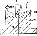
Here, the shape of each the lens shape equivalence that must accurately be processed into and intend being processed in patrix 2 and the counterdie 3.Fig. 2 A and 2B represent to make by machining the situation of this die forming.In addition, because the forming process of patrix 2 is identical with the forming process of counterdie 3, omit description so only describe a back process to patrix 2 with reference to Fig. 2 A and 2B.Referring to Fig. 2 A, counterdie 3 is made up of with a layer 3a who becomes to be processed basic part 3b.Layer 3a for example resembled the thin slice formation of platinum (Pt) or iridium (Ir) system by noble metal.The reason of doing like this is, because the fusing point height of glass, so require to intend when forming lens, can not being fused on glass by its material of making layer 3a.Layer 3a utilizes the cutter head of being made by diamond and so on 5, is machined into the shape with the diffraction optics partial shape equivalence of lens.So shown in Fig. 2 B, after layer 3a is processed to specific shape, on the surface of layer 3a, form a protective seam 6, partly lose its shape to prevent this diffraction optics.
Yet, above-mentioned by the cutting ability difference noble metal such as the thin slice of platinum (Pt) or iridium (Ir) system forms layer, its machining process exists cutter head, and a large amount of wear problems can take place.In order to address this problem, can consider to change the material of layer to be processed into material from noble metal with good cutting, chemical nickel plating for example, yet there is other problem in chemical nickel plating in this case, because the fusing point height of glass, so may be fused on glass during at the formation lens or consumed sharp at the chemical Ni-plating layer on the die surface.
Summary of the invention
The object of the present invention is to provide a kind of lens with high-NA, its manufacture method and the optical sense pick-up head that uses these lens that can accurately and efficiently make with low cost.
In order to achieve the above object, according to a first aspect of the invention, provide a kind of lens, it comprises: a geometrical optics part is used to assemble from the incident of its light plane of incidence light on it; And be provided at the light plane of incidence of this geometrical optics part and two diffraction optics parts on the light exit plane, wherein this diffraction optics part is made by the material that is different from the geometrical optics part, and interconnects.Described diffraction optics part is made by glass or resin, and described geometrical optics part is made by glass or resin.For this structure, by the material that the is different from geometrical optics part diffraction optics part made of resin for example, be connected on the light plane of incidence and light exit plane of this geometrical optics part, therefore might form the diffraction optics part easily.
In order to achieve the above object, according to a second aspect of the invention, the method that provides a kind of manufacturing to comprise the lens of geometrical optics part and two diffraction optics part, it comprises the steps: to add in first mould that its shape is equivalent to this geometrical optics partial shape being used to form geometrical optics material partly; By first mould is exerted pressure this material pressure is shaped, to form this geometrical optics part; The material that is used to form the diffraction optics part is injected second mould that its shape is equivalent to this diffraction optics partial shape; And the geometrical optics that will form by pressure forming partly is placed in second mould, geometrical optics partly is connected on the diffraction optics part.Described diffraction optics part is made by glass or resin, and described geometrical optics part is made by glass or resin.For this structure, because the material that is used for forming the diffraction optics part for example resin is to be connected on the light plane of incidence that gives the geometrical optics part that forms earlier and the light exit plane to form this diffraction optics part, therefore might be in this formation diffraction optics part easily above geometrical optics part.
In order to achieve the above object, according to a third aspect of the invention we, provide a kind of optical sense pick-up head, it comprises: one is used to export the light source of a laser beam; One laser beam that is used for being sent by this light source is beamed into the light-dividing device of several portions; One is used for the laser beam from this light-dividing device is focused at object lens on the signal record plane of optical record medium; An and optical detector that is used to detect the laser beam of returning by this signal record plane reflection, wherein these object lens comprise geometrical optics part and the two diffraction optics parts that are formed on this geometrical optics part, and the diffraction optics part is made by the material that is different from the geometrical optics part.Described diffraction optics part is made by glass or resin, and described geometrical optics part is made by glass or resin.For this structure, these object lens are shaped as, by being different from the diffraction optics part that geometrical optics material is partly made, be connected on the light plane of incidence and light exit plane of this geometrical optics part, therefore might on the geometrical optics part, form the diffraction optics part easily, thereby, by using a kind of lens that have high-NA and little spherical aberration and can low-cost high-efficiency produce, can low cost provide a kind of high performance optical sense pick-up head.
Description of drawings
Figure 1A and 1B make the structural drawing of device one example of the integrally formed lens of hologram according to correlation technique for expression;
The structural drawing of situation when Fig. 2 A and 2B are shaped by machine work for mould shown in expression Figure 1A and the 1B;
Fig. 3 is the system diagram of expression optical sense pick-up head preferred embodiment of the present invention;
Fig. 4 is the sectional view of expression lens preferred embodiment of the present invention;
Fig. 5 A to 5C is the structural drawing of geometrical optics part situation when processed of expression lens shown in Figure 4, and
Fig. 6 A to 6E is the structural drawing of diffraction optics part situation when processed of expression lens shown in Figure 4.
Subsequently, the preferred embodiments of the present invention are described in detail with reference to the accompanying drawings.
Embodiment
Fig. 3 is the structural drawing of the optical sense pick-up head of the expression preferred embodiment of the present invention.Describe optical sense pick-up head 10 in detail now with reference to Fig. 3.
Optical sense pick-up head 10 shown in Figure 3 comprises the beam splitter 12 of a light source 11, as light-dividing device, collimation lens 13, object lens 14 and optical detector 15.
The laser beam that is incident on the collimation lens 13 is carried out collimation, and is incident upon above the object lens 14.This laser beam is focused on the signal record plane D1 of the poly-D of light by object lens 14 then.From the laser beam that the signal record plane reflection of CD D is returned, be incident on object lens 14, collimation lens 13 successively and above the beam splitter 12, and enter optical detector 15 from beam splitting coating 12a reflection.The laser beam that optical detector 15 is suitable for returning converts electric signal to, and exports a read output signal or like that.
Fig. 4 is the sectional view of the object lens 14 of the expression preferred embodiment of the present invention.Object lens 14 shown in Figure 4 comprise geometrical optics part 20 and diffraction optics part 21.Geometrical optics part 20 for example is made of the non-spherical lens that glass is made.More particularly, geometrical optics part 20 is convex lens, is used to assemble by the laser beam of light plane of incidence 20a incident on it.The diffraction optics part 21b of the diffraction optics part 21a of light plane of incidence one side and light exit plane one side is formed on the light plane of incidence 20a of geometrical optics part 20 respectively and above the first exit plane 20b.By the diffraction optics part 21 that the diffraction optics part 21b of the diffraction optics part 21a of light plane of incidence one side and light exit plane one side forms, for example make by CR39 (thermoset resin) or photo-curable resin (as ultraviolet curable resin).Diffraction optics part 21 is processed into glitter shape or zigzag fashion.
Be incident on laser beam on the object lens 14 from light plane of incidence 20a, almost by the whole diffraction of diffraction optics part 21a of light plane of incidence one side and assemble and be incident on the geometrical optics part 20.Geometrical optics part 20 is assembled the laser beam of incident with the function of convex lens, and makes this laser beam incident on the diffraction optics part 21b of light exit plane one side.The diffraction optics part 21b of light exit plane one side is almost with the laser-beam diffraction of whole incidents, thereby further this laser beam assembled.Therefore, object lens 14 obtain high numerical aperture NA.Object lens 14 for example shown in Figure 4 have thickness that L is 3.035mm and the diameter of φ 5.76mm, and it reaches NA is 0.85 numerical aperture.
In the present embodiment, for the similar whole incoming laser beam of diffraction, diffraction optics part 21 is shaped as that to have the degree of depth and the scope that scope is 600~700nm be the tooth pitch of 0.020~0.340nm, wherein this degree of depth and tooth pitch radially change according to certain way, and the degree of depth narrows down so that edge its tooth pitch of direction from object lens 14 centers to the periphery diminishes.
The structural drawing of state when Fig. 5 A to 5C and 6A to 6E produce object lens 14 for expression.The production run of the object lens 14 of so-called profiling technology is described in detail with reference to Fig. 5 A to 5C and 6A to 6E.The process of making object lens 14 generally is divided into the process of making geometrical optics part 20 and the process of making diffraction optics part 21.At first, with reference to Fig. 5 A to 5C the process of making geometrical optics part 20 is described.
Fig. 5 A represents a mould 30, comprises a patrix 31 and a counterdie 32, and the space of Xing Chenging has and geometrical optics part 20 essentially identical shapes therebetween, is used for glass is added therein.At first glass is added in the space between upper and lower mould 31 and 32.
In this case, the glass of scheduled volume is added into spherical shape to be formed.Then, for fear of welding between mould 30 and the glass, inert gas is filled in the progressive die tool 30, and glass is heated to the temperature that can be shaped.Be heated at glass and have that patrix 31 is moved after the specific glutinousness, for example the direction of representing along Y2 among Fig. 5 B is shaped to make glass pressure by it is exerted pressure.This glass is cooled off gradually, and cooling rapidly then is to obtain the geometrical optics part 20 shown in Fig. 5 C.
Subsequent, the process of diffraction optics part 21 is described with reference to Fig. 6 A to 6E.In addition, although only describe the last process that forms diffraction optics part 21 of light plane of incidence 20a of geometrical optics part 20 shown in Figure 4, yet this diffraction optics part 21 can be formed on the light exit plane 20b in fact also by the patrix (not shown) with reference to Fig. 6 A to 6E.At first, as shown in Figure 6A, prepare a counterdie 40, its surface is processed to the shape with the shape equivalence of diffraction optics part 21.The main body that this counterdie 40 is made by the wimet (as tungsten carbide) of basic material of stainless steel or sintering constitutes, and wherein chemical nickel plating is used on this main body.Chemical Ni-plating layer on the counterdie 40 uses the cutter head by diamond system to carry out machining by single-point turning, with the shape of formation with the shape equivalence of diffraction optics part 21.By providing chemical nickel coating on the surface of counterdie 40, the processibility of counterdie 40 improves, thereby forms easily the shape with the shape equivalence of diffraction optics part 21 on the surface of counterdie 40.In this case, because but diffraction optics part 21 is to be made by shapable resin under than the lower temperature of the forming temperature of glass, so when forming diffraction optics part 21 by the chemical Ni-plating layer that forms on the counterdie 40, the chemical Ni-plating layer that is formed on the counterdie 40 there is no fear of welding.
Be used to form the resin of diffraction optics part 21, be provided for counterdie 40.This resin stands froth in vacuum then, and counterdie 40 along direction shown in the arrow R11 around its axis CL high speed rotating.Therefore, shown in Fig. 6 B, resin is maintained at plan and forms diffraction optics part 21 needed amounts on counterdie 40.
Then shown in Fig. 6 C, in process shown in Fig. 5 A to 5C produced geometrical optics part 20 by assembly on the resin of coating on the counterdie 40, thereby diffraction optics part 21a is connected on the light plane of incidence 20a of geometrical optics part 20.Subsequent shown in Fig. 6 D, under the situation of using ultraviolet curable resin, this resin is illuminated with ultraviolet ray; Under the situation of using heat reactive resin, this resin is cured by heating mould.According to this approach, shown in Fig. 6 E, diffraction optics part 21 is formed on the light plane of incidence 20a of geometrical optics part 20.
According to the foregoing description, the lens 14 with high-NA and gratifying transmission wavefront aberration can create.And, have in the process of lens 14 of geometrical optics part 20 and diffraction optics part 21 in manufacturing, because geometrical optics part 20 and diffraction optics part 21 are formed separately, so might be by shifting the shape that accurately obtains diffraction optics part 21, and produce lens 14 with low cost from mould 40.In addition, be machined easily owing to form the mould 40 of diffraction optics part 21 usefulness, so lens 14 can create efficiently.In addition, by using the lens of producing with low-cost high-efficiency 14 as object lens, the total cost of optical sense pick-up head 10 can be lowered.
The present invention is not limited to the foregoing description.Although object lens 14 are to make according to the so-called reproduction process that Fig. 5 A to 5C and Fig. 6 A to 6E represent, but it also can will partly be plugged on the injection molding that is used for mold pressing diffraction optics part 21 by the geometrical optics that glass is made by so-called grafting mold process (insert molding process), and carry out the resin injection molding around geometrical optics part 20.Though the lens 14 shown in Fig. 5 A to 5C and Fig. 6 A to 6E are shaped as the object lens 14 with high-NA, it also can be shaped as the bifocal lens of geometrical optics part 20 and 21 combinations of diffraction optics part.
In addition, in the above-described embodiments, lens of the present invention are used as the object lens 14 of optical sense pick-up head 10 shown in Figure 3, yet it also can be applicable to collector lens, for example the image pickup lens.In addition, object lens 14 shown in Figure 4 are made according to two processes, yet these two processes also can use same device only to finish by changing mould.
Although the preferred embodiments of the present invention have used specific term to be carried out description, yet this description only for illustrative purposes, and should be appreciated that many variations and adjust and all can accomplish, and do not depart from the spirit or scope of following claim.
Claims (14)
1. lens comprise:
One is used to assemble the geometrical optics part by its its glazing of light plane of incidence incident, and
Be provided at the light plane of incidence of above-mentioned geometrical optics part and two diffraction optics parts on the light exit plane,
Wherein said diffraction optics part is made by the material different with the material of above-mentioned geometrical optics part,
Described diffraction optics part is made by glass or resin, and described geometrical optics part is made by glass or resin.
2. according to the lens of claim 1, the fusing point of wherein said diffraction optics part material is lower than the fusing point of described geometry light part material.
3. according to the lens of claim 1, each in the wherein said diffraction optics part forms the shape of glittering.
4. according to the lens of claim 1, wherein said geometrical optics is partly made by glass.
5. according to the lens of claim 1, wherein said geometrical optics partly is a non-spherical lens.
6. according to the lens of claim 1, wherein said diffraction optics partly is formed from a resin.
7. a manufacturing comprises the method for geometrical optics part and two diffraction optics lens partly, may further comprise the steps:
The material that is used to form described geometrical optics part is added in first mould that its inner space has the shape that is equivalent to described geometrical optics partial shape, and this material pressure is shaped, forming described geometrical optics part, and
The material that is used to form described diffraction optics part is injected second mould that its surface is shaped as the shape that is equivalent to described diffraction optics partial shape, and will partly be added in described second mould by pressure-formed described geometrical optics, so that described geometrical optics partly is connected on the described diffraction optics part
Described diffraction optics part is made by glass or resin, and described geometrical optics part is made by glass or resin.
8. according to the manufacturing lens method of claim 7, the step of the described diffraction optics part of wherein said formation comprises the step of rotating described second mould around the optical axis of described lens.
9. optical sense pick-up head comprises:
One is used for the light source of outgoing one laser beam;
One laser beam that is used for sending from described light source is beamed into the light-dividing device of mass part;
One is used for the laser beam from described light-dividing device is focused at object lens on the signal record plane of an optical record medium, and
One is used to detect the optical detector of the laser beam of being returned by described signal record plane reflection,
Wherein said mirror mirror comprises that geometrical optics part and two is formed in the diffraction optics parts on the described geometrical optics part, and described diffraction optics part is by making with described geometrical optics material partly material inequality,
Described diffraction optics part is made by glass or resin, and described geometrical optics part is made by glass or resin.
10. according to the optical sense pick-up head of claim 9, the fusing point of wherein said diffraction optics part material is lower than the fusing point of described geometrical optics part material.
11. according to the optical sense pick-up head of claim 9, each in the wherein said diffraction optics part forms a shape of glittering.
12. according to the optical sense pick-up head of claim 9, wherein said geometrical optics part is made by glass.
13. according to the optical sense pick-up head of claim 9, wherein said geometrical optics partly is a non-spherical lens.
14. according to the optical sense pick-up head of claim 9, wherein said diffraction optics partly is formed from a resin.
Applications Claiming Priority (3)
| Application Number | Priority Date | Filing Date | Title |
|---|---|---|---|
| JP20382998A JP3900693B2 (en) | 1998-07-17 | 1998-07-17 | Lens manufacturing method |
| JP203829/1998 | 1998-07-17 | ||
| JP203829/98 | 1998-07-17 |
Publications (2)
| Publication Number | Publication Date |
|---|---|
| CN1243307A CN1243307A (en) | 2000-02-02 |
| CN1117350C true CN1117350C (en) | 2003-08-06 |
Family
ID=16480406
Family Applications (1)
| Application Number | Title | Priority Date | Filing Date |
|---|---|---|---|
| CN99110481A Expired - Fee Related CN1117350C (en) | 1998-07-17 | 1999-07-16 | Lens, its mfg. method and optical sense pick-up head |
Country Status (6)
| Country | Link |
|---|---|
| US (2) | US6215591B1 (en) |
| JP (1) | JP3900693B2 (en) |
| KR (1) | KR100592860B1 (en) |
| CN (1) | CN1117350C (en) |
| MY (1) | MY126199A (en) |
| SG (1) | SG78375A1 (en) |
Families Citing this family (17)
| Publication number | Priority date | Publication date | Assignee | Title |
|---|---|---|---|---|
| JPH10186230A (en) * | 1996-10-29 | 1998-07-14 | Canon Inc | Lens system and optical instrument |
| US6965165B2 (en) * | 1998-12-21 | 2005-11-15 | Mou-Shiung Lin | Top layers of metal for high performance IC's |
| JP4595184B2 (en) * | 2000-10-02 | 2010-12-08 | コニカミノルタホールディングス株式会社 | Optical pickup device and objective lens |
| WO2002037484A2 (en) * | 2000-10-30 | 2002-05-10 | Konica Corporation | Objective lens, light converging optical system, optical pickup apparatus, and recording/reproducing apparatus |
| TW571116B (en) * | 2001-02-28 | 2004-01-11 | Sony Corp | Optical pickup-use object lens, optical pickup and optical disk unit |
| KR20030020364A (en) * | 2001-05-22 | 2003-03-08 | 소니 가부시끼 가이샤 | Objective lens for optical pick up, optical pick up and disk drive device |
| US20030174374A1 (en) * | 2001-12-11 | 2003-09-18 | Pentax Corporation | Scanning optical system |
| JP4313686B2 (en) * | 2004-01-29 | 2009-08-12 | 富士フイルム株式会社 | Manufacturing method of mold for annular optical element |
| JP2006059517A (en) * | 2004-07-23 | 2006-03-02 | Konica Minolta Opto Inc | Compound optical device and optical pickup device |
| CN103461303B (en) * | 2006-12-21 | 2018-05-08 | 美国陶氏益农公司 | Include the composite material of thermoplastic polymer, pest food material and insecticide |
| WO2008153102A1 (en) | 2007-06-14 | 2008-12-18 | Aji Co., Ltd. | Method of molding, process for producing lens, molding apparatus, process for producing stamper, master production apparatus, stamper production system and stamper production apparatus |
| WO2010073573A1 (en) * | 2008-12-26 | 2010-07-01 | パナソニック株式会社 | Diffractive lens and image pickup device using the same |
| US8240849B2 (en) * | 2009-03-31 | 2012-08-14 | Johnson & Johnson Vision Care, Inc. | Free form lens with refractive index variations |
| TW201300845A (en) | 2011-06-17 | 2013-01-01 | Univ Nat Chiao Tung | Lens device and method of manufacturing the same |
| DE102012023025A1 (en) | 2012-11-23 | 2014-05-28 | Rodenstock Gmbh | Production of microstructured spectacle lenses by means of a transfer layer |
| CN107654961A (en) * | 2015-06-29 | 2018-02-02 | 福建鸿博光电科技有限公司 | Avoid the lens and LED lamp of destructurized variable luminous intensity distribution |
| CN111637645A (en) * | 2020-05-20 | 2020-09-08 | 杨金玉 | Application of glass linear Fresnel lens in solar energy |
Family Cites Families (8)
| Publication number | Priority date | Publication date | Assignee | Title |
|---|---|---|---|---|
| JPS62288030A (en) | 1986-06-06 | 1987-12-14 | Matsushita Electric Ind Co Ltd | Manufacturing device for composite linse |
| JPH0416910A (en) * | 1990-05-11 | 1992-01-21 | Omron Corp | Optical lens |
| US6180033B1 (en) * | 1992-08-19 | 2001-01-30 | Chrysalis Development Company, Llc | Method of making a finished multi-coated and/or laminated eyeglass lens |
| US5528321A (en) * | 1992-11-23 | 1996-06-18 | Innotech, Inc. | Method of manufacturing contact lenses |
| US5566027A (en) * | 1993-01-18 | 1996-10-15 | Canon Kabushiki Kaisha | Photocurable resin composition and optical lens produced therefrom |
| KR100200868B1 (en) * | 1995-12-22 | 1999-06-15 | 윤종용 | Optical pickup device |
| US5978140A (en) * | 1996-10-24 | 1999-11-02 | Asahi Kogaku Kogyo Kabushiki Kaisha | Method for designing diffractive lenses |
| US6305194B1 (en) * | 1999-07-15 | 2001-10-23 | Eastman Kodak Company | Mold and compression molding method for microlens arrays |
-
1998
- 1998-07-17 JP JP20382998A patent/JP3900693B2/en not_active Expired - Fee Related
-
1999
- 1999-07-14 US US09/352,753 patent/US6215591B1/en not_active Expired - Fee Related
- 1999-07-14 MY MYPI99002954A patent/MY126199A/en unknown
- 1999-07-15 SG SG1999003380A patent/SG78375A1/en unknown
- 1999-07-16 CN CN99110481A patent/CN1117350C/en not_active Expired - Fee Related
- 1999-07-16 KR KR1019990028806A patent/KR100592860B1/en not_active IP Right Cessation
-
2001
- 2001-02-20 US US09/788,922 patent/US6783707B2/en not_active Expired - Fee Related
Also Published As
| Publication number | Publication date |
|---|---|
| KR20000011761A (en) | 2000-02-25 |
| JP3900693B2 (en) | 2007-04-04 |
| JP2000040247A (en) | 2000-02-08 |
| KR100592860B1 (en) | 2006-06-23 |
| US6783707B2 (en) | 2004-08-31 |
| US6215591B1 (en) | 2001-04-10 |
| MY126199A (en) | 2006-09-29 |
| US20010015849A1 (en) | 2001-08-23 |
| SG78375A1 (en) | 2001-02-20 |
| CN1243307A (en) | 2000-02-02 |
Similar Documents
| Publication | Publication Date | Title |
|---|---|---|
| CN1117350C (en) | Lens, its mfg. method and optical sense pick-up head | |
| CN1209759C (en) | Object lens for optical pick-up head unit | |
| JP4110506B2 (en) | Mold for optical element molding | |
| JP4525677B2 (en) | Manufacturing method of mold for molding optical element | |
| US6229782B1 (en) | High numerical aperture optical focusing device for use in data storage systems | |
| US20060077795A1 (en) | Objective optical system for optical recording media and optical pickup device using it | |
| JPWO2007145117A1 (en) | Compound lens and manufacturing method thereof | |
| JP4305722B2 (en) | Manufacturing method of molded lens | |
| US7179536B1 (en) | Optical element having a low surface roughness, an optical pickup device including the optical element, and a die for making the optical element | |
| CN1864213A (en) | Optical recording substrate, optical recording medium, and manufacturing method thereof | |
| EP0892396B1 (en) | Hologram laser unit and two-focus type optical pickup | |
| US7301880B2 (en) | Write-once optical disc, and method and apparatus for recording/reproducing management information on/from optical disc | |
| EP1308944A2 (en) | Method of producing information recording medium, production apparatus and information recording medium | |
| US7785689B2 (en) | Raw material conserving optical data storage media | |
| JPWO2007145116A1 (en) | Composite optical element and manufacturing method thereof | |
| JP3830138B2 (en) | MULTILAYER STRUCTURE OPTICAL RECORDING MEDIUM AND METHOD FOR PRODUCING THE OPTICAL RECORDING MEDIUM | |
| US6862259B2 (en) | Optical lens, optical pickup apparatus, and optical disk apparatus using the same | |
| JP2007310000A (en) | Compound optical element | |
| JPH06162553A (en) | Optical information read-out device |
Legal Events
| Date | Code | Title | Description |
|---|---|---|---|
| C06 | Publication | ||
| PB01 | Publication | ||
| C10 | Entry into substantive examination | ||
| SE01 | Entry into force of request for substantive examination | ||
| C14 | Grant of patent or utility model | ||
| GR01 | Patent grant | ||
| C17 | Cessation of patent right | ||
| CF01 | Termination of patent right due to non-payment of annual fee |
Granted publication date: 20030806 |