CN111672991A - Positioning fixture is used in production of metal stamping product - Google Patents
Positioning fixture is used in production of metal stamping product Download PDFInfo
- Publication number
- CN111672991A CN111672991A CN202010336597.2A CN202010336597A CN111672991A CN 111672991 A CN111672991 A CN 111672991A CN 202010336597 A CN202010336597 A CN 202010336597A CN 111672991 A CN111672991 A CN 111672991A
- Authority
- CN
- China
- Prior art keywords
- platform
- clamp
- plate
- movable
- base platform
- Prior art date
- Legal status (The legal status is an assumption and is not a legal conclusion. Google has not performed a legal analysis and makes no representation as to the accuracy of the status listed.)
- Granted
Links
Images


Classifications
-
- B—PERFORMING OPERATIONS; TRANSPORTING
- B21—MECHANICAL METAL-WORKING WITHOUT ESSENTIALLY REMOVING MATERIAL; PUNCHING METAL
- B21D—WORKING OR PROCESSING OF SHEET METAL OR METAL TUBES, RODS OR PROFILES WITHOUT ESSENTIALLY REMOVING MATERIAL; PUNCHING METAL
- B21D43/00—Feeding, positioning or storing devices combined with, or arranged in, or specially adapted for use in connection with, apparatus for working or processing sheet metal, metal tubes or metal profiles; Associations therewith of cutting devices
- B21D43/003—Positioning devices
-
- B—PERFORMING OPERATIONS; TRANSPORTING
- B21—MECHANICAL METAL-WORKING WITHOUT ESSENTIALLY REMOVING MATERIAL; PUNCHING METAL
- B21C—MANUFACTURE OF METAL SHEETS, WIRE, RODS, TUBES OR PROFILES, OTHERWISE THAN BY ROLLING; AUXILIARY OPERATIONS USED IN CONNECTION WITH METAL-WORKING WITHOUT ESSENTIALLY REMOVING MATERIAL
- B21C51/00—Measuring, gauging, indicating, counting, or marking devices specially adapted for use in the production or manipulation of material in accordance with subclasses B21B - B21F
Landscapes
- Engineering & Computer Science (AREA)
- Mechanical Engineering (AREA)
- Bending Of Plates, Rods, And Pipes (AREA)
Abstract
The invention discloses a positioning clamp for producing a metal stamping product, relates to the technical field of positioning clamps, and aims to solve the problems that in the prior art, the shape of a metal plate to be stamped is a rectangular or square structure, but the size of the metal plate to be stamped is different due to the influence of cutting, and the shape is deviated when stamping processing is carried out if timely adjustment is not carried out before fixing. The bottom of sheet metal anchor clamps subassembly is provided with the work base platform, the top of work base platform is provided with the elevating platform, and elevates platform and work base platform telescopic connection, the top of elevating platform is provided with the punching press template, and punching press template and elevating platform combination link, the both sides of elevating platform all are provided with main fixation clamp platform, and just main fixation clamp platform passes through interval track sliding connection with the work base platform, the both sides of work base platform one end are provided with perpendicular branch, and just perpendicular branch passes through bolted connection with the work base platform, the top of perpendicular branch is provided with horizontal sliding rod.
Description
Technical Field
The invention relates to the technical field of positioning fixtures, in particular to a positioning fixture for producing a metal stamping product.
Background
The jig is a device for fixing a machining object to a correct position for construction or inspection in a machine manufacturing process, and is also called a jig, and broadly speaking, a device for quickly, conveniently and safely installing a workpiece in any process in a process is called a jig, and the jig generally comprises a positioning element, a clamping device, a tool setting guide element, an indexing device, a connecting element, a jig body and the like, and the types of the jig can be classified according to the use characteristics: universal clamp, such as vice, chuck, sucking disc, dividing head and rotary table, etc. has great versatility, can better adapt to the change of the processing procedure and the processing object, the structure is already shaped, the size and the specification are already serialized, and most of them become a standard accessory of the machine tool; the special fixture is specially designed and manufactured for the clamping requirement of a certain product part on a certain process, has a specific service object and strong pertinence, is generally designed by a product manufacturer, and is commonly used as a lathe fixture, a milling machine fixture, a drill jig, a boring jig and a follower fixture; adjustable clamp, special clamp capable of replacing or adjusting element; modular fixtures, consisting of standardized elements of different shapes, specifications and uses, are suitable for single-piece, small-lot production and temporary tasks of trial production of new products and frequent replacement of products.
However, the existing metal plate to be stamped is of a rectangular or square structure, but the sizes of the metal plate to be stamped are different due to cutting, and if the metal plate to be stamped is not adjusted in time before being fixed, the shape of the metal plate to be stamped deviates during stamping; therefore, the existing requirements are not met, and the positioning clamp for producing the metal stamping product is provided for the requirement.
Disclosure of Invention
The invention aims to provide a positioning clamp for producing a metal stamping product, which aims to solve the problems that the shape of a metal plate to be stamped in the background art is a rectangular or square structure, but the sizes of the metal plate to be stamped are different due to the influence of cutting, and the shape is deviated when stamping processing is carried out if timely adjustment is not carried out before fixing.
In order to achieve the purpose, the invention provides the following technical scheme: a positioning fixture for producing metal stamping products comprises a metal plate fixture assembly, wherein a working base platform is arranged at the bottom of the metal plate fixture assembly, an elevating platform is arranged above the working base platform and is in telescopic connection with the working base platform, a stamping template is arranged above the elevating platform and is in combined connection with the elevating platform, main fixing clamp platforms are arranged on two sides of the elevating platform and are in sliding connection with the working base platform through spacing tracks, vertical supporting rods are arranged on two sides of one end of the working base platform and are in bolted connection with the working base platform, a horizontal sliding rod is arranged above the vertical supporting rods, knob adjusting blocks are arranged at two ends of the horizontal sliding rod and are in sliding connection with the vertical supporting rods, a movable sliding block is arranged on the surface of the horizontal sliding rod, an infrared scanning calculation assembly is arranged at the bottom of the movable sliding block, and the infrared scanning calculation component is connected with the movable sliding block in a combined manner, and an infrared scanning port is arranged at the bottom of the infrared scanning calculation component.
Preferably, one side of main fixed clamp platform is provided with power supply machine box, and power supply machine box passes through bolted connection with main fixed clamp platform, the top of main fixed clamp platform is provided with movable clamp plate, and movable clamp plate and main fixed clamp platform pass through and press from both sides tight track sliding connection, movable clamp plate's top is provided with signal control machine box, and signal control machine box passes through the screw connection with movable clamp plate.
Preferably, the bottom of the movable clamping plate is provided with a second plate clamp group, the top of the main fixing clamping table is provided with a first plate clamp group, the first plate clamp group and the second plate clamp group comprise wheel axle clamp assemblies, and the number of the wheel axle clamp assemblies is four.
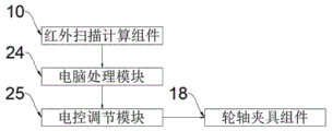
Preferably, the input end of the wheel axle clamp assembly is connected with the output end of the electronic control adjusting module, the input end of the electronic control adjusting module is connected with the output end of the computer processing module, and the input end of the computer processing module is connected with the output end of the infrared scanning computing assembly.
Preferably, the wheel axle clamp assembly comprises a contraction plate groove, and the contraction plate groove is connected with the movable clamp plate and the main fixed clamp platform through clamping grooves.
Preferably, one end of the contraction plate groove is provided with a movable rotating shaft, the movable rotating shaft is in telescopic connection with the contraction plate groove, an electric control driving wheel frame is arranged above the movable rotating shaft, and the electric control driving wheel frame is in rotary connection with the movable rotating shaft.
Preferably, a rubber wheel shaft is arranged on the inner side of the electric control driving wheel frame and is rotationally connected with the electric control driving wheel frame.
Preferably, the rubber wheel shaft is internally provided with a roller counting and sensing assembly, and the roller counting and sensing assembly is connected with the rubber wheel shaft in a combined manner.
Compared with the prior art, the invention has the beneficial effects that:
1. according to the invention, the shape area of the plate is scanned through the infrared scanning calculation component, the shape volumes of different plates are obtained, the scanning data are uploaded to the control computer, the data are analyzed by the computer, then various control signals are sent by the computer, and the central area is found according to the plates with different shape volumes so as to carry out processing, so that the processing precision is ensured, and the yield is improved;
2. the invention clamps and fixes the plate by the upper and lower groups of wheel axle clamp assemblies, the wheel axle clamp assemblies have the main structure of the rubber wheel axle, the rubber material on the surface of the rubber wheel axle can increase the friction force between the rubber wheel axle and the plate, after the plate is clamped and fixed by the upper and lower groups of rubber wheel axles, the movement control of the plate can be realized by the rotation of the wheel axle, the wheel axle is rotationally connected with the movable rotating shaft by the electrically controlled driving wheel frame, so the rotating direction of the wheel axle can be controlled by the rotation of the rotating shaft, thereby the front, back, left and right movement adjustment of the plate is realized, the movable rotating shaft is telescopically connected with the contraction plate groove at one end, so the integral telescopic operation of the wheel axle can be controlled, the wheel axle is required to be firstly separated from the surface of the plate when the direction is adjusted, so that the plate is prevented from being deviated in the adjusting process, generally, the wheel sets on two sides are clamped and fixed, the two wheel shafts in the middle are contracted and rotationally adjusted, after the adjustment is finished, the wheel sets in the middle are in contact with the plate, the wheel sets on two sides are retracted, efficient operation is achieved through alternate work, and time is saved;
3. the roller counting sensing assemblies are arranged in each group of rubber wheel shafts, the number of turns of the corresponding wheel shaft can be detected through the roller counting sensing assemblies, and then the moving distance of the plate can be obtained by multiplying the number of turns by the circumference of the wheel shaft, so that the position of the plate can be accurately regulated and controlled.
Drawings
FIG. 1 is an overall front view of the present invention;
FIG. 2 is a side view of the primary retention clip station of the present invention;
FIG. 3 is an enlarged structural diagram A of the present invention;
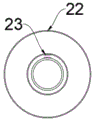
FIG. 4 is a schematic view of the construction of a rubber wheel axle according to the present invention;
FIG. 5 is a flow chart of the detection according to the present invention.
In the figure: 1. a work base; 2. a raising platform; 3. stamping the template; 4. a main stationary clamping table; 5. a pitch track; 6. a vertical strut; 7. a knob adjusting block; 8. a horizontal sliding bar; 9. moving the slide block; 10. an infrared scanning calculation component; 11. an infrared scanning port; 12. a power supply box; 13. a movable splint; 14. clamping the rail; 15. a signal control box; 16. a first panel clamp group; 17. a second panel clamp group; 18. an axle clamp assembly; 19. a shrink plate slot; 20. a movable rotating shaft; 21. an electrically controlled driving wheel carrier; 22. a rubber wheel shaft; 23. a roller counting sensing assembly; 24. a computer processing module; 25. an electronic control adjusting module; 26. sheet metal clamp assembly.
Detailed Description
The technical solutions in the embodiments of the present invention will be clearly and completely described below with reference to the drawings in the embodiments of the present invention, and it is obvious that the described embodiments are only a part of the embodiments of the present invention, and not all of the embodiments.
Referring to fig. 1-5, an embodiment of the present invention is shown: a positioning fixture for producing metal stamping products comprises a metal plate fixture component 26, wherein the bottom of the metal plate fixture component 26 is provided with a working base platform 1, an elevating platform 2 is arranged above the working base platform 1 and plays a role in supporting and fixing, the elevating platform 2 is telescopically connected with the working base platform 1, a stamping template 3 is arranged above the elevating platform 2, the stamping template 3 is connected with the elevating platform 2 in a combined manner, two sides of the elevating platform 2 are respectively provided with a main fixing clamp platform 4, the main fixing clamp platforms 4 are slidably connected with the working base platform 1 through an interval track 5, two sides of one end of the working base platform 1 are provided with vertical support rods 6, the vertical support rods 6 are connected with the working base platform 1 through bolts, horizontal slide rods 8 are arranged above the vertical support rods 6, two ends of the horizontal slide rods 8 are respectively provided with knob adjusting blocks 7, and the knob adjusting blocks 7 are slidably connected with the vertical support rods 6, the height of the intelligent control device can be adjusted and controlled, a moving sliding block 9 is arranged on the surface of a horizontal sliding rod 8, the sliding block can horizontally move back and forth along the sliding rod, an infrared scanning calculation component 10 is arranged at the bottom of the moving sliding block 9, the infrared scanning calculation component 10 is connected with the moving sliding block 9 in a combined mode, an infrared scanning port 11 is formed in the bottom of the infrared scanning calculation component 10, and the object is globally scanned through infrared rays, so that the shape and length and width data information of the object are obtained.
Further, one side of main fixed clamp platform 4 is provided with power supply machine box 12, and power supply machine box 12 passes through bolted connection with main fixed clamp platform 4, and the top of main fixed clamp platform 4 is provided with movable clamp plate 13, and movable clamp plate 13 passes through clamping track 14 sliding connection with main fixed clamp platform 4, realizes the tight operating function of clamp's clamp, and the top of movable clamp plate 13 is provided with signal control machine box 15 for receive the control signal of computer, and signal control machine box 15 passes through the screw connection with movable clamp plate 13.
Further, the bottom of the movable clamping plate 13 is provided with a second plate clamp group 17, after the plate is placed, the second plate clamp group 17 descends to be matched with the first plate clamp group 16 to clamp the plate in the middle, the top of the main fixing clamping table 4 is provided with the first plate clamp group 16 as a supporting structure for the plate, the first plate clamp group 16 and the second plate clamp group 17 comprise wheel axle clamp assemblies 18, the number of the wheel axle clamp assemblies 18 is four, and the plate is clamped and fixed through the wheel axle clamp assemblies 18.
Further, the input of shaft anchor clamps subassembly 18 is connected with the output of automatically controlled adjusting module 25, the input of automatically controlled adjusting module 25 is connected with the output of computer processing module 24, the input of computer processing module 24 is connected with the output of infrared scanning calculation subassembly 10, put into the anchor clamps with sheet metal from the one end of infrared scanning, when the plate moves to the inboard afterwards, thereby the shape area of plate is scanned through the function of making a round trip of infrared scanning calculation subassembly 10, and with scanning data upload to the control computer, carry out the analysis by the computer to data.
Further, the wheel axle clamp assembly 18 comprises a contraction plate groove 19, and the contraction plate groove 19 is connected with the movable clamping plate 13 and the main fixing clamping table 4 through clamping grooves, so that the installation and the fixation are facilitated.
Further, one end of the contraction plate groove 19 is provided with a movable rotating shaft 20, the movable rotating shaft 20 is in telescopic connection with the contraction plate groove 19, the retraction of the wheel shaft is controlled, the wheel shaft needs to be separated from the surface of the plate firstly when the direction of the wheel shaft is adjusted, so that the plate is prevented from being deviated, an electric control driving wheel frame 21 is arranged above the movable rotating shaft 20, the electric control driving wheel frame 21 is rotatably connected with the movable rotating shaft 20, the rotating direction of the wheel shaft can be controlled through the rotation of the rotating shaft, and therefore the plate can be adjusted in a front-back left-right movement mode.
Further, a rubber wheel shaft 22 is arranged on the inner side of the electric control driving wheel frame 21, the rubber wheel shaft 22 is rotatably connected with the electric control driving wheel frame 21, the plate is clamped and fixed through the upper and lower groups of rubber wheel shafts 22, and the movement control of the plate can be realized through the rotation of the wheel shafts.
Further, the inside of rubber wheel axle 22 is provided with gyro wheel count sensing component 23, and gyro wheel count sensing component 23 and rubber wheel axle 22 built-up connection, and gyro wheel count sensing component 23 can detect corresponding shaft pivoted number of turns, and the system can obtain the displacement of plate according to the girth of shaft multiply the number of turns afterwards to the position of accurate regulation and control plate.
The working principle is as follows: when in use, the stamping template is placed on the elevating platform 2 above the working base platform 1, then the height of the horizontal sliding rod 8 is controlled by the knob adjusting block 7, the surface of the horizontal sliding rod 8 is provided with a moving slide block 9, the slide block can horizontally move back and forth along the sliding rod, after the horizontal sliding rod 8 is started, a metal plate to be stamped is placed on the first plate clamp group 16 on the main fixing clamp platforms 4 at two sides from one end of infrared scanning, after the plate is placed, the movable clamp plate 13 above the main fixing clamp platforms 4 descends along the clamping track 14 to drive the second plate clamp group 17 at the bottom of the movable clamp groups to descend so as to be matched with the first plate clamp group 16 to clamp the plate in the middle, the inner sides of the upper and lower two groups of plate clamp groups are provided with four wheel axle clamp assemblies 18, the wheel axle clamp assemblies 18 have the main structure of a rubber wheel axle 22, and the rubber material on the surfaces of the rubber axle clamp assemblies can increase the, after the upper and lower groups of rubber wheel shafts 22 clamp and fix the plate, the plate can be controlled by the rotation of the wheel shafts, the wheel shafts are rotationally connected with a movable rotating shaft 20 through an electric control driving wheel carrier 21, so that the rotating direction of the wheel shafts can be controlled by the rotation of the rotating shaft, the plate can be adjusted in a front-back and left-right movement manner, the movable rotating shaft 20 is telescopically connected with a contraction plate groove 19 at one end, so that the whole telescopic operation of the wheel shafts can be controlled, the wheel shafts need to be separated from the surface of the plate firstly when the direction is adjusted, so that the plate is prevented from being deviated in the adjusting process, finally, a roller counting sensing assembly 23 is arranged in each group of rubber wheel shafts 22, the corresponding number of turns of the wheel shafts can be detected through the roller counting sensing assembly 23, and the moving distance of the plate can be obtained by multiplying the number of turns of the, thereby the position of accurate regulation and control plate, so after the plate is fixed and when moving through the wheel axle inboard, thereby the infrared scanning calculation subassembly 10 of one end just can make a round trip to operate scans the shape area of plate to with scan data upload to the control computer, carry out the analysis by the computer to data, then send various control signal by the computer, thereby the plate according to different shape volumes comes the accurate central region of finding and processes.
It will be evident to those skilled in the art that the invention is not limited to the details of the foregoing illustrative embodiments, and that the present invention may be embodied in other specific forms without departing from the spirit or essential attributes thereof. The present embodiments are therefore to be considered in all respects as illustrative and not restrictive, the scope of the invention being indicated by the appended claims rather than by the foregoing description, and all changes which come within the meaning and range of equivalency of the claims are therefore intended to be embraced therein. Any reference sign in a claim should not be construed as limiting the claim concerned.
Claims (8)
1. The utility model provides a positioning fixture is used in production of metal stamping product, includes sheet metal piece anchor clamps subassembly (26), its characterized in that: the bottom of the metal plate clamp assembly (26) is provided with a working base platform (1), an elevated platform (2) is arranged above the working base platform (1), the elevated platform (2) is in telescopic connection with the working base platform (1), a stamping template (3) is arranged above the elevated platform (2), the stamping template (3) is in combined connection with the elevated platform (2), main fixing clamp platforms (4) are arranged on two sides of the elevated platform (2), the main fixing clamp platforms (4) are in sliding connection with the working base platform (1) through spacing tracks (5), vertical support rods (6) are arranged on two sides of one end of the working base platform (1), the vertical support rods (6) are connected with the working base platform (1) through bolts, horizontal slide rods (8) are arranged above the vertical support rods (6), knob adjusting blocks (7) are arranged at two ends of the horizontal slide rods (8), and knob regulating block (7) and vertical support rod (6) sliding connection, the surface of horizontal slide bar (8) is provided with removes slider (9), the bottom of removing slider (9) is provided with infrared scanning calculation subassembly (10), and infrared scanning calculation subassembly (10) and remove slider (9) built-up connection, the bottom of infrared scanning calculation subassembly (10) is provided with infrared scanning mouth (11).
2. The positioning jig for producing the metal stamped product as set forth in claim 1, wherein: one side of main fixed clamp platform (4) is provided with power machine box (12), and power machine box (12) passes through bolted connection with main fixed clamp platform (4), the top of main fixed clamp platform (4) is provided with movable clamp plate (13), and movable clamp plate (13) and main fixed clamp platform (4) through pressing from both sides tight track (14) sliding connection, the top of movable clamp plate (13) is provided with signal control machine box (15), and signal control machine box (15) pass through the screw connection with movable clamp plate (13).
3. The positioning jig for producing the metal stamped product as set forth in claim 2, wherein: the bottom of the movable clamping plate (13) is provided with a second plate clamp group (17), the top of the main fixed clamping table (4) is provided with a first plate clamp group (16), the first plate clamp group (16) and the second plate clamp group (17) comprise wheel axle clamp assemblies (18), and the number of the wheel axle clamp assemblies (18) is four.
4. The positioning jig for producing the metal stamped product as set forth in claim 3, wherein: the input end of the wheel axle clamp assembly (18) is connected with the output end of the electronic control adjusting module (25), the input end of the electronic control adjusting module (25) is connected with the output end of the computer processing module (24), and the input end of the computer processing module (24) is connected with the output end of the infrared scanning computing assembly (10).
5. The positioning jig for producing the metal stamped product as set forth in claim 3, wherein: the wheel axle clamp assembly (18) comprises a contraction plate groove (19), and the contraction plate groove (19) is connected with the movable clamping plate (13) and the main fixed clamping table (4) through clamping grooves.
6. The positioning jig for producing the metal stamped product as set forth in claim 5, wherein: one end of the contraction plate groove (19) is provided with a movable rotating shaft (20), the movable rotating shaft (20) is in telescopic connection with the contraction plate groove (19), an electric control driving wheel frame (21) is arranged above the movable rotating shaft (20), and the electric control driving wheel frame (21) is rotatably connected with the movable rotating shaft (20).
7. The positioning jig for producing the metal stamped product as set forth in claim 6, wherein: the inner side of the electric control driving wheel frame (21) is provided with a rubber wheel shaft (22), and the rubber wheel shaft (22) is rotationally connected with the electric control driving wheel frame (21).
8. The positioning jig for producing a metal stamped product according to claim 7, characterized in that: and a roller counting and sensing assembly (23) is arranged in the rubber wheel shaft (22), and the roller counting and sensing assembly (23) is connected with the rubber wheel shaft (22) in a combined manner.
Priority Applications (1)
| Application Number | Priority Date | Filing Date | Title |
|---|---|---|---|
| CN202010336597.2A CN111672991B (en) | 2020-04-26 | 2020-04-26 | Positioning fixture is used in production of metal stamping product |
Applications Claiming Priority (1)
| Application Number | Priority Date | Filing Date | Title |
|---|---|---|---|
| CN202010336597.2A CN111672991B (en) | 2020-04-26 | 2020-04-26 | Positioning fixture is used in production of metal stamping product |
Publications (2)
| Publication Number | Publication Date |
|---|---|
| CN111672991A true CN111672991A (en) | 2020-09-18 |
| CN111672991B CN111672991B (en) | 2022-04-19 |
Family
ID=72452158
Family Applications (1)
| Application Number | Title | Priority Date | Filing Date |
|---|---|---|---|
| CN202010336597.2A Active CN111672991B (en) | 2020-04-26 | 2020-04-26 | Positioning fixture is used in production of metal stamping product |
Country Status (1)
| Country | Link |
|---|---|
| CN (1) | CN111672991B (en) |
Cited By (2)
| Publication number | Priority date | Publication date | Assignee | Title |
|---|---|---|---|---|
| CN113083771A (en) * | 2021-03-29 | 2021-07-09 | 中科宁图技术江苏有限公司 | Dust removal device and dust removal method based on intelligent analysis |
| CN114951402A (en) * | 2022-08-03 | 2022-08-30 | 成都工业职业技术学院 | Forming device of computer shell |
Citations (8)
| Publication number | Priority date | Publication date | Assignee | Title |
|---|---|---|---|---|
| CN203744948U (en) * | 2013-12-31 | 2014-07-30 | 长城汽车股份有限公司 | Vehicle special-shaped steel plate size inspection device |
| CN204780605U (en) * | 2015-05-11 | 2015-11-18 | 中交四公局第三工程有限公司 | Prestressed anchorage cable machine of reeving |
| CN206105552U (en) * | 2016-08-31 | 2017-04-19 | 安吉万昌家具有限公司 | Table chair board chamfer processing equipment |
| TWM556382U (en) * | 2017-09-22 | 2018-03-01 | 財團法人金屬工業研究發展中心 | Contour measurement system |
| CN209716257U (en) * | 2019-03-15 | 2019-12-03 | 苏州奇圣钣金有限公司 | A kind of metal plate device for clamping mould |
| CN110732919A (en) * | 2019-09-18 | 2020-01-31 | 南京六和普什机械有限公司 | Hole repairing device for stamping parts |
| CN110763107A (en) * | 2019-11-11 | 2020-02-07 | 徐州涡轮空间汽车科技有限公司 | Detection device for automobile accessory production |
| CN110918804A (en) * | 2019-12-23 | 2020-03-27 | 苏州苏宏模具有限公司 | Stamping part inserting piece device |
-
2020
- 2020-04-26 CN CN202010336597.2A patent/CN111672991B/en active Active
Patent Citations (8)
| Publication number | Priority date | Publication date | Assignee | Title |
|---|---|---|---|---|
| CN203744948U (en) * | 2013-12-31 | 2014-07-30 | 长城汽车股份有限公司 | Vehicle special-shaped steel plate size inspection device |
| CN204780605U (en) * | 2015-05-11 | 2015-11-18 | 中交四公局第三工程有限公司 | Prestressed anchorage cable machine of reeving |
| CN206105552U (en) * | 2016-08-31 | 2017-04-19 | 安吉万昌家具有限公司 | Table chair board chamfer processing equipment |
| TWM556382U (en) * | 2017-09-22 | 2018-03-01 | 財團法人金屬工業研究發展中心 | Contour measurement system |
| CN209716257U (en) * | 2019-03-15 | 2019-12-03 | 苏州奇圣钣金有限公司 | A kind of metal plate device for clamping mould |
| CN110732919A (en) * | 2019-09-18 | 2020-01-31 | 南京六和普什机械有限公司 | Hole repairing device for stamping parts |
| CN110763107A (en) * | 2019-11-11 | 2020-02-07 | 徐州涡轮空间汽车科技有限公司 | Detection device for automobile accessory production |
| CN110918804A (en) * | 2019-12-23 | 2020-03-27 | 苏州苏宏模具有限公司 | Stamping part inserting piece device |
Cited By (3)
| Publication number | Priority date | Publication date | Assignee | Title |
|---|---|---|---|---|
| CN113083771A (en) * | 2021-03-29 | 2021-07-09 | 中科宁图技术江苏有限公司 | Dust removal device and dust removal method based on intelligent analysis |
| CN114951402A (en) * | 2022-08-03 | 2022-08-30 | 成都工业职业技术学院 | Forming device of computer shell |
| CN114951402B (en) * | 2022-08-03 | 2022-10-21 | 成都工业职业技术学院 | Forming device of computer shell |
Also Published As
| Publication number | Publication date |
|---|---|
| CN111672991B (en) | 2022-04-19 |
Similar Documents
| Publication | Publication Date | Title |
|---|---|---|
| CN106803566B (en) | Cutting device for battery core tab | |
| CN111672991B (en) | Positioning fixture is used in production of metal stamping product | |
| CN202169481U (en) | Vertical post array type machine body wall plate assembling and locating device | |
| CN110465579B (en) | Automatic punching equipment and using method thereof | |
| CN106876649B (en) | Battery core tab cutting device | |
| CN106876650B (en) | Electric core tab leveling, detecting and cutting system | |
| CN110640551B (en) | Intelligent and automatic sand box production line | |
| CN111113064B (en) | High-precision production and processing equipment for various types of brake discs | |
| CN214421665U (en) | Detection mark module | |
| CN213196655U (en) | Dabber inclined hole processing tool of height and horizontal position adjustable | |
| CN209936433U (en) | Work fixture | |
| CN114378677A (en) | Pull down punch production is with surface machining equipment that has levelness and detect structure | |
| CN210059862U (en) | Novel multi-position adjustable radial drilling machine | |
| CN209793209U (en) | Frock is used in piston machining | |
| CN217668983U (en) | Fixing tool for disc parts | |
| CN215615240U (en) | High-precision quick punching device for guide rail sliding block production | |
| CN220718569U (en) | Gantry milling and grinding compound machine guide rail machining device | |
| CN220592334U (en) | Clamping device for CNC machining center | |
| CN219855030U (en) | Panel processing location fluting device | |
| CN217252524U (en) | Concentric rotary swaging automatic feeding and positioning device | |
| CN217166577U (en) | Drilling machine with drilling precision adjusting function for steel plate drilling | |
| CN220865103U (en) | Printing device for channel steel machining | |
| CN220575669U (en) | Positioning tool for machining planet carrier | |
| CN212704986U (en) | Adjustable supporting mechanism of clamping and pushing device of steel strip welding machine | |
| CN214560226U (en) | Dynamic auxiliary mechanism for measurement |
Legal Events
| Date | Code | Title | Description |
|---|---|---|---|
| PB01 | Publication | ||
| PB01 | Publication | ||
| SE01 | Entry into force of request for substantive examination | ||
| SE01 | Entry into force of request for substantive examination | ||
| GR01 | Patent grant | ||
| GR01 | Patent grant |