Detailed Description
For the purpose of making the objects, technical solutions and advantages of the embodiments of the present invention more apparent, the technical solutions in the embodiments will be clearly and completely described with reference to the accompanying drawings in the embodiments of the present invention, and the following embodiments are used to illustrate the present invention, but are not intended to limit the scope of the present invention.
In the description of the present invention, it should be noted that the directions or positional relationships indicated by the terms "upper", "lower", "front", "rear", "left", "right", "vertical", "inner", "outer", etc. are based on the directions or positional relationships shown in the drawings, are merely for convenience of describing the present invention and simplifying the description, and do not indicate or imply that the devices or elements referred to must have a specific orientation, be configured and operated in a specific orientation, and thus should not be construed as limiting the present invention.
In the description of the present invention, it should be noted that, unless explicitly specified and limited otherwise, the terms "mounted," "connected," and "connected" are to be construed broadly, and may be either fixedly connected, detachably connected, or integrally connected, for example; can be mechanically or electrically connected; can be directly connected or indirectly connected through an intermediate medium. The specific meaning of the above terms in the present invention will be understood in specific cases by those of ordinary skill in the art.
As shown in fig. 1 to 18, the present embodiment provides a drum washing machine of a front open type structure of a non-porous inner tub, which has a simple structure and can greatly reduce the amount of washing water used for the washing machine without filling washing/rinsing water between the inner tub and the outer tub. Avoiding the possibility of dirt adhesion between the inner cylinder and the outer cylinder. The health and the user experience of the user are greatly improved, and the water resource is greatly saved.
The drum washing machine of the present embodiment has a housing 19, and the housing 19 includes: top deck 2, front deck, back deck and bottom deck. A foot 9 is fixed on the bottom plate for supporting the whole washing machine. The housing 19 has an outer tube 18 inside, and an inner tube 17 is coaxially provided in the outer tube 18. The outer tube 18 is mainly for collecting the drain water of the inner tube 17 and the drain water of the inner tube 17 by high-speed centrifugal dehydration. The inner drum 17 rotates, preferably with lifting ribs 43, to continuously lift, drop and beat the laundry to wash the laundry. The inner barrel 17 is of non-porous construction. The outer tube 18 has a central mounting hole to which the bearing 12 is mounted and secured. An inner cylinder shaft 13, which is fixedly connected to an inner cylinder 17, passes through the bearing 12 shown and is connected to a drive 16. An openable/closable inner cylinder door 6 is arranged on the front cylinder opening of the inner cylinder 17, so that the inner cylinder 17 is of a sealed cabin structure.
The housing 19 of the present embodiment is provided with an openable/closable door 5.
Example 1
The embodiment mainly solves the problem of how to accurately determine the water inflow of the pore-free inner barrel drum washing machine, and the specific scheme is as follows:
the drum washing machine comprises an inner drum 17 and a water inlet pipeline communicated with the inner drum 17, wherein the inner drum 17 is a non-porous inner drum, washing water is contained during washing clothes, and a flow sensor 1 for detecting the flow of the water inlet is arranged on the water inlet pipeline.
In this embodiment, the flow sensor 1 is disposed on the water inlet pipe to monitor the flow rate of the water when the water inlet reaches the set water inlet amount, and the water inlet valve 20 is closed to complete water inlet. The flow sensor is adopted in the embodiment, so that the problem of water inflow of the pore-free inner barrel drum washing machine according to the set water level is solved, the washing effect is ensured, the structure is simple, and the control is convenient.
Further, the drum washing machine of this embodiment includes a water inlet valve 20 and a detergent box 3, the water inlet pipe includes a first water inlet pipe and a second water inlet pipe, an outlet end of the water inlet valve 20 is communicated with the detergent box 3 through the first water inlet pipe, an outlet end of the detergent box 3 is communicated with the inner drum 17 through the second water inlet pipe, and the flow sensor 1 is disposed on the first water inlet pipe or the second water inlet pipe.
Preferably, the flow sensor 1 is arranged on the first inlet pipe, so that the detergent in the detergent box can be placed into the flow sensor 1.
The drum washing machine of the embodiment comprises a main controller 4, wherein the flow sensor 1 is electrically connected with the main controller 4 through a circuit. The main controller 4 can collect the water inflow of the inner cylinder 17 in real time, the water inflow reaches the set water inflow, and the water inlet valve 20 is closed.
As an implementation manner of the present embodiment, the flow sensor 1 is a rotor flow sensor, a turbine flow sensor, an ultrasonic flow sensor, an electromagnetic flow sensor, or an orifice flow sensor.
The flow sensor 1 can be arranged at any position on the water inlet pipe, preferably at the rear part of the water inlet valve 20, and can accurately measure the water flow entering the sealed inner cylinder 17, the flow sensor 1 is connected with the main controller 4, the main controller 4 can collect the water inflow of the inner cylinder 17 in real time, the set water inflow is achieved, and the water inlet valve 20 is closed.
In order to realize water inflow into the nonporous inner cylinder of the embodiment, the drum washing machine of the embodiment comprises a driving motor 16 and an inner cylinder shaft 13, wherein the driving motor 16 is in transmission connection with the inner cylinder 17 through the inner cylinder shaft 13 to drive the inner cylinder 17 to rotate, the inner cylinder shaft 13 is internally provided with a hollow channel 14 communicated with the inner cylinder 17, and the water inflow pipeline is communicated with the hollow channel of the inner cylinder shaft 13.
Specifically, the inner cylinder shaft 13 is connected with a driving motor 16, the driving motor 16 comprises a stator and a rotor, and the rotor is fixedly connected with the inner cylinder shaft 13; the center of the rotor is provided with a through hole, and the water inlet pipeline penetrates through the through hole of the rotor and is communicated with the hollow channel 14 of the inner barrel shaft 13.
Further, a first dynamic sealing structure 15 is arranged between the water inlet pipeline and the through hole of the rotor, and a second sealing structure is arranged between the through hole of the rotor and the hollow channel 14 of the inner cylinder shaft 13.
In order to realize the drainage of the pore-free inner cylinder, the drum washing machine of the embodiment comprises an outer cylinder 18, an inner cylinder drainage hole is formed in the side wall of the inner cylinder 17, a normally closed one-way valve plug 11 is arranged on the inner cylinder drainage hole, and a push rod mechanism 10 for pushing the one-way valve plug 11 open for drainage is arranged on the outer cylinder 18.
Preferably, a locking mechanism for locking the rotation of the inner cylinder 17 is further arranged on the outer cylinder 18, and the locking mechanism pushes the one-way valve plug 11 open for drainage after the inner cylinder is locked by the locking mechanism.
In order to realize the dehydration of the inner barrel without holes, a plurality of dehydration holes are formed in the side wall of the inner barrel 17, centrifugal valves are arranged on the dehydration holes, and the centrifugal valves are opened to carry out dehydration and drainage under the action of dehydration centrifugal force.
The embodiment also provides a control method of the drum washing machine, wherein the washing machine executes a washing/rinsing program, in the water inlet process, a flow sensor detects the water inlet flow value in real time, the washing machine calculates the water inlet amount according to the water inlet flow value and the water inlet time, and when the water inlet amount reaches the set water inlet amount of the washing machine, the water inlet is stopped.
The drum washing machine is provided with a plurality of inflow flow values which can be selected by a user, and the washing machine performs water inflow according to the inflow flow values selected by the user.
The drum washing machine has a clothes weighing function, and can determine the flow value of water inflow according to the weight of clothes to perform water inflow.
Example two
As shown in fig. 2-4, the drum washing machine of this embodiment includes an inner drum 17 and a water inlet pipeline, the inner drum is a non-porous inner drum, and holds washing water during washing clothes, and further includes a water metering device for metering water inflow, the water inlet pipeline is communicated with the water metering device, and the water metering device is communicated with the inner drum.
The drum washing machine of this embodiment is through setting up water measuring device, enters into the water measuring device before the water intaking in inwards 1 and carries out quantitative measuring in earlier, confirms the number of times of water measuring device water measuring according to the water level that sets for to solved the problem of intaking of aporate inner tube drum washing machine according to the water level that sets for, ensured the washing effect, simple structure, it is convenient to control.
Further, the water measuring device in this embodiment includes a water measuring tank 21, the water measuring tank 21 has a water inlet and a water outlet, the water inlet is connected with the water inlet pipeline, and the water outlet is connected with the inner cylinder 17; the water outlet is provided with a water outlet control device for controlling the opening of the water outlet when the water quantity in the water tank 21 reaches a set value.
As an implementation manner of this embodiment, as shown in fig. 2, the water tank 21 is disposed at the bottom of the inner cylinder 17, the water tank includes a water level detecting device 22 for detecting the water tank 21, the water outlet control device is a water tank drain pump 23, and the water tank drain pump 23 is started to pump water in the water tank 21 into the inner cylinder 17 when the water level detecting device 22 detects that the water level in the water tank 21 reaches a set value.
As an implementation manner of this embodiment, as shown in fig. 3, the water tank 21 is disposed at an upper portion of the inner cylinder 17, the water tank includes a water level detecting device 22 for detecting the water tank, the water outlet control device is a water tank drain valve 25, and the water tank drain valve 25 is opened to drain water in the water tank 21 into the inner cylinder when the water level detecting device 22 detects that the water level in the water tank 21 reaches a set value.
The water level detecting device 22 in this embodiment is a liquid level sensor, and the liquid level sensor includes an air chamber and a sensor unit, wherein the air chamber is communicated with a water tank. Alternatively, the water level detecting means 22 may include a plurality of water level detecting probes arranged in the depth direction thereof in the water tank.
As an implementation manner of this embodiment, the water tank 21 is disposed at the upper portion of the inner cylinder 17, the water outlet is disposed on the bottom wall of the water tank 21, the water outlet control device is a water tank check valve that keeps the water outlet normally closed, and when the water amount in the equivalent water tank reaches a certain value, the water tank check valve is opened under the gravity of water pressure, and after the water in the water tank 21 is discharged into the inner cylinder 17, the water tank check valve resets to keep the water outlet closed.
The overflow hole 24 is arranged on the water tank 21 in the embodiment, and the overflow hole 24 is connected with an overflow pipeline for guiding out the overflowed water in the water tank.
Preferably, the drum washing machine comprises a drain pipe 8, and the overflow pipe is communicated with the drain pipe 8.
As an implementation of the present embodiment, as shown in fig. 4, the water measuring device includes a heating device 26 provided in the water measuring tank 21 and a water temperature detecting device detecting the water temperature in the water measuring tank.
The embodiment also provides a control method of the drum washing machine, the washing machine executes a washing/rinsing program, the washing machine controls washing water to enter the water tank, when the water quantity in the water tank reaches a set value, water inflow is stopped, water in the water tank is completely discharged into the inner drum, water inflow is started again to enter the water tank, and circulation is performed until the water level in the inner drum reaches the set value, and water inflow is ended.
Further, the washing machine controls the washing water to enter the water measuring tank, when the water quantity in the water measuring tank reaches a set value, water inflow is stopped, the heating device is controlled to operate to heat the washing water, and when the water temperature detection device detects that the water temperature in the water measuring tank reaches the set value, the water in the water measuring tank is completely discharged into the inner barrel.
Example III
The embodiment mainly solves the problem of how to ensure the unbalanced air pressure of the sealed cabin of the non-porous inner cylinder drum washing machine, and particularly, the sudden water interruption of the electromagnetic valve, especially the water interruption of a tap water pipe network, forms negative pressure and backflushes the washing water in the sealed cabin to the pipe network; or the gas exists in the water tank, and the water is difficult to enter.
As shown in fig. 5-7, the drum washing machine of the present embodiment includes an inner drum 17, wherein the inner drum 17 is a non-porous inner drum, and is used for containing washing water during washing clothes, and further includes an air pressure balancing mechanism for communicating the inner drum 17 with the external environment to balance the air pressure inside the inner drum.
When water is fed, the air in the sealed cabin of the inner cylinder is pressurized and overflows through the balance mechanism, so that air pressure balance is ensured.
When water is suddenly cut off, the external atmosphere can rapidly enter the sealed cabin of the inner cylinder, reverse suction is destroyed, air pressure balance is ensured, and washing water is prevented from being sucked into a tap water pipe network.
The air pressure balance mechanism can ensure the air pressure balance of the inner cylinder when other materials are dehydrated.
As an implementation manner of this embodiment, the air pressure balancing mechanism includes a pressure equalizing hole 27 disposed on the inner cylinder 17, where one end of the pressure equalizing hole 27, which is connected to the inner cylinder 17, is disposed on the inner cylinder 17 near the rotation center axis and is always higher than the highest water level in the inner cylinder 17.
The drum washing machine of the embodiment comprises a driving motor 16 and an inner drum shaft 13, wherein the driving motor 16 is in transmission connection with the inner drum 17 through the inner drum shaft 13 to drive the inner drum 17 to rotate, a pressure equalizing pore canal 27 is formed in the inner drum shaft 13 to communicate the inner drum 17 with the external environment, and the highest water level in the inner drum 17 is lower than that of the inner drum shaft 13. Thus, the water in the inner cylinder can be prevented from flowing out from the pressure equalizing pore canal.
The drum washing machine of this embodiment includes urceolus 18, inner tube 17 set up in urceolus 18 inside, the water that discharges in the inner tube 17 is discharged through urceolus 18, the inner tube door 6 of sealed inner tube is installed to the nozzle of inner tube 17, the nozzle of urceolus 18 is opened, the one end intercommunication inner tube 17 inside of pressure equalizing duct 27, the other end sets up in urceolus 18 inside and communicates with each other. In this way, the extreme case is prevented, and the hole water can also be collected in the outer tub 18.
Further, in this embodiment, an inner cylinder drain hole is formed in the side wall of the inner cylinder 17, a normally closed one-way valve plug 11 is installed on the inner cylinder drain hole, and a push rod mechanism 10 for pushing the one-way valve plug 11 open to drain water is installed on the outer cylinder 18.
Preferably, a locking mechanism for locking the rotation of the inner cylinder is further arranged on the outer cylinder 18, and the locking mechanism pushes the one-way valve plug open for draining after the inner cylinder is locked by the locking mechanism.
Further, the drum washing machine of the embodiment includes a water inlet pipeline, the inner drum shaft 13 is provided with a hollow channel 14 communicating with the inner drum 17, and the water inlet pipeline is communicated with the hollow channel 14 of the inner drum shaft 13; the pressure equalizing pore canal 27 and the hollow channel 14 are respectively communicated with the inner part of the inner cylinder 17 and are mutually isolated. Thus, the gas in the sealed cabin of the inner cylinder can be smoothly discharged to keep the air pressure balance in the inner cylinder, and meanwhile, the water inflow is prevented from being directly discharged from the pressure equalizing pore canal 27 to leak water.
Specifically, the hollow channel 27 extends from one end to the other end along the central axis direction of the inner cylinder shaft, the pressure equalizing channel comprises a first channel section and a second channel section, the first channel section is arranged in parallel with the hollow channel, one end of the first channel section is communicated with the inside of the inner cylinder, one end of the second channel section is communicated with the first channel section, and the other end of the second channel section extends to the peripheral wall of the inner cylinder shaft to be communicated with the inside of the outer cylinder.
Preferably, the second duct section is perpendicular to the first duct section to form an L-shaped pressure equalizing duct.
Further, the inner cylinder shaft 13 is connected with a driving motor 16, the driving motor 16 comprises a stator and a rotor, and the rotor is fixedly connected with the inner cylinder shaft; the center of the rotor is provided with a through hole, and the water inlet pipeline penetrates through the through hole of the rotor and is communicated with the hollow channel of the inner cylinder shaft.
Preferably, a first dynamic sealing structure is arranged between the water inlet pipeline and the through hole of the rotor, and a second sealing structure is arranged between the through hole of the rotor and the hollow channel of the inner cylinder shaft.
In the drum washing machine of this embodiment, a plurality of dewatering holes are formed in the side wall of the inner drum 17, and centrifugal valves are installed in the dewatering holes, and are opened to dewater and drain under the action of dewatering centrifugal force.
Example IV
The embodiment mainly solves the problem of how to ensure the unbalanced air pressure of the sealed cabin of the non-porous inner cylinder drum washing machine, and particularly, the sudden water interruption of the electromagnetic valve, especially the water interruption of a tap water pipe network, forms negative pressure and backflushes the washing water in the sealed cabin to the pipe network; or the gas exists in the water tank, and the water is difficult to enter.
As shown in fig. 8-12, the drum washing machine of the present embodiment includes an inner drum 17, wherein the inner drum 17 is a non-porous inner drum, and is used for containing washing water during washing clothes, and further includes a pressurizing mechanism and/or a pressure releasing mechanism for communicating the inner drum with the external environment to balance the air pressure inside the inner drum 17.
The pressurizing mechanism in this embodiment includes a pressurizing channel 28 and a negative pressure relief valve 29, the negative pressure relief valve 29 is disposed on the pressurizing channel 28, and is used for conducting the pressurizing channel 28 in a unidirectional manner when the internal pressure of the inner cylinder 17 is smaller than the external atmospheric pressure, and the external atmospheric gas enters the inner cylinder 17 from the pressurizing channel 28 to be pressurized until the internal air pressure of the inner cylinder 17 is balanced with the external atmospheric pressure, and the negative pressure relief valve 29 is closed.
The pressure release mechanism in this embodiment includes pressure release pore canal 30 and positive pressure relief valve 31, pressure release pore canal 30 set up on inner tube 17 be close to rotation center axis position department and be higher than the highest water level position in the inner tube 17 all the time, positive pressure relief valve 31 set up on pressure release pore canal 30 for the pressure release is carried out to the unidirectional conduction pressure release pore canal 30 when inner tube 17 internal pressure is greater than external environment atmospheric pressure, until inner tube 17 internal air pressure and external environment atmospheric pressure balance, positive pressure relief valve 31 is closed.
As shown in fig. 9, when water is fed, the gas in the sealed cabin of the inner cylinder 17 is pressurized, and once the pressure is larger than the set value of the positive pressure safety valve, the positive pressure safety valve is opened and overflows through the pressure relief pore canal, so that the air pressure balance is ensured.
As shown in fig. 10, when water is suddenly cut off, the air in the sealed cabin of the inner cylinder 17 is pressurized, once the air is smaller than the set value of the positive pressure safety valve, the external atmosphere can rapidly enter the sealed cabin, reverse suction is destroyed, air pressure balance is ensured, and washing water is prevented from being sucked into a tap water pipe network.
The air pressure balance mechanism can ensure the air pressure balance of the inner cylinder when other materials are dehydrated.
The drum washing machine of this embodiment includes driving motor 16 and inner tube axle 13, driving motor 16 drive inner tube 17 rotation through interior tube axle 13 and inner tube 17 transmission connection, pressure boost pore 28 and/or pressure release pore 30 set up on inner tube axle 13 intercommunication inner tube 17 inside and external environment, the highest water level in inner tube 17 is less than inner tube axle 13.
The drum washing machine of this embodiment includes the urceolus 18, the inner tube 17 set up in urceolus 18 inside, the water that discharges in the inner tube 17 is discharged through urceolus 18, the drum mouth installation of inner tube 17 seals the inner tube door 6 of inner tube, the drum mouth of urceolus 18 is opened, the one end intercommunication inner tube 17 inside of pressure boost pore canal 28 and/or pressure release pore canal 30, the other end sets up in urceolus 18 inside and communicates with each other.
The drum washing machine of the embodiment comprises a water inlet pipeline, wherein a hollow channel 14 communicated with the inside of an inner drum 17 is arranged in the inner drum shaft 13, and the water inlet pipeline is communicated with the hollow channel 14 of the inner drum shaft 13; the pressure relief pore canal 30 and the hollow channel 14 are respectively communicated with the inner part of the inner cylinder 17 and are mutually isolated.
As shown in fig. 9 and 10, the hollow channel 14 extends from one end to the other end along the central axis direction of the inner cylinder shaft 13, the pressure relief channel 30 includes a first channel section and a second channel section, the first channel section is parallel to the hollow channel, one end of the first channel section is communicated with the inner cylinder, one end of the second channel section is communicated with the first channel section, and the other end extends to the outer peripheral wall of the inner cylinder shaft to be communicated with the inner part of the outer cylinder;
Preferably, the second duct section is perpendicular to the first duct section to form an L-shaped pressure relief duct.
The drum washing machine of the embodiment comprises a water inlet pipeline, wherein a hollow channel 14 communicated with the inside of an inner drum 17 is arranged in the inner drum shaft 13, and the water inlet pipeline is communicated with the hollow channel 14 of the inner drum shaft 13; the plenum duct 28 communicates with the hollow passage 14.
Further, the hollow passage 14 extends from one end to the other end along the central axis direction of the inner cylinder shaft 13, one end of the pressurizing passage 28 is communicated with the hollow passage 14, and the other end extends to the outer peripheral wall of the inner cylinder shaft 13 and is communicated with the inside of the outer cylinder 18.
Preferably, the plenum 28 is disposed perpendicular to the hollow passage 14.
The inner cylinder shaft is connected with a driving motor, the driving motor comprises a stator and a rotor, and the rotor is fixedly connected with the inner cylinder shaft; the center of the rotor is provided with a through hole, and the water inlet pipeline penetrates through the through hole of the rotor and is communicated with the hollow channel of the inner cylinder shaft.
Preferably, a first dynamic sealing structure is arranged between the water inlet pipeline and the through hole of the rotor, and a second sealing structure is arranged between the through hole of the rotor and the hollow channel of the inner cylinder shaft.
As shown in fig. 11 and 12, the pressurizing duct 28 and the pressure releasing duct 30 are both provided on the inner cylinder shaft 13, and the communicating atmosphere openings are both inside the outer cylinder 18; the openings of the sealed cabins communicated with the inner cylinder 17 are all at the inner side of the water inlet channel 14 of the inner cylinder shaft 13.
It may be mentioned that the preferred pressurizing duct 28 and the pressure releasing duct 30 are both provided on the inner cylinder shaft 13, and the communicating atmosphere openings are both inside the outer cylinder 18; the openings of the capsule communicating with the inner tube 17 are all inside the capsule.
Example five
As shown in fig. 13 to 16, a drum washing machine of the present embodiment includes an inner tub 17, the inner tub 17 being a non-porous inner tub, and a position detecting device for detecting a position of the inner tub when washing laundry.
The drum washing machine of this embodiment includes driving motor 16 and inner drum shaft 13, and driving motor 16 includes stator and rotor, and rotor and inner drum shaft 13 fixed connection drive inner drum 17 rotation, position detection device include position sensor 33 and by the detection terminal 38, by the detection terminal 38 set up on the rotor, position sensor 33 fix with by the position that detects terminal 38 corresponds.
The drum washing machine of the present embodiment includes an outer tub 18, and the position sensor 33 is disposed on one side of the outer tub 18 near the driving motor 16, and the position sensor 33 is disposed corresponding to the detected terminal 38 at a distance.
As an implementation manner of this embodiment, the position sensor is an electromagnetic position sensor, or a photoelectric position sensor, or a differential voltage sensor, or an eddy current sensor, or a capacitive sensor, or a reed switch sensor, or a hall sensor.
The drum washing machine of this embodiment includes a locking mechanism 35 for locking the rotation of the inner drum, and the position detecting device is used for detecting whether the inner drum 17 is locked in place after the locking mechanism 35 locks the inner drum 17, and/or locking the inner drum 17 after the position detecting device detects that the inner drum 17 rotates to a set position.
Further, the locking mechanism 35 is mounted on the side wall of the outer cylinder 18 close to the driving motor 16, the locking mechanism 35 comprises a locking rod 40 moving telescopically and a locking motor 41 driving the locking rod 40 to move telescopically, a locking groove 39 matched with the locking rod 40 is arranged on the rotor of the driving motor 16, and when the locking rod 40 is driven by the locking motor 41 to extend out and be inserted into the locking groove 39, the inner cylinder 17 is locked.
In the drum washing machine of the embodiment, an inner drum drain hole is formed in the side wall of the inner drum 17, a normally closed one-way valve plug 11 is arranged on the inner drum drain hole, and a push rod mechanism 10 for pushing the one-way valve plug open to drain is arranged on the outer drum; the locking mechanism 35 locks the inner cylinder 17 and then the ejector rod mechanism 10 pushes the one-way valve plug 11 open for drainage.
Further, the ejector rod mechanism is arranged on the outer cylinder and comprises an ejector rod in telescopic motion and an ejector rod motor for driving the ejector rod to perform telescopic motion, and the ejector rod penetrates through the wall of the outer cylinder and is inserted into a drain hole of the inner cylinder to jack up the one-way valve plug for draining.
The drum washing machine of the embodiment comprises a main controller, wherein the position detection sensor, the locking motor and the ejector rod motor are all electrically connected with the main controller.
In the drum washing machine of this embodiment, a plurality of dehydration holes are formed in the side wall of the inner drum, and centrifugal valves are mounted on the dehydration holes, and the centrifugal valves are opened to perform dehydration and drainage under the action of dehydration centrifugal force.
The washing machine of the present embodiment has a position sensor 33 provided on the outer tub 18 and the driving motor 16, specifically, on the rear of the outer tub 18 and the rotor frame rotated by the driving motor 16.
The position sensor 33 senses the position of the detected terminal 38 on the rotating rotor frame, converts the position into a signal, and feeds the signal back to the main controller 4 of the washing machine via a line 43.
The position of the detected terminal 38 on the rotor frame corresponds to the position of the rotating inner cylinder.
The washing machine of the embodiment is provided with a mounting bracket 32, a fixing knot 34 is fixed behind the outer cylinder, and a locking motor, a locking rod and a position sensor are arranged on the mounting bracket 32; the rotor frame of the drive motor has a lock groove and a detected terminal 38.
Example six
As shown in fig. 17 to 18, a drum washing machine of this embodiment includes an inner tub 17 and an outer tub 18, the inner tub 17 is a non-porous inner tub, and holds washing water when washing laundry, the outer tub 18 is coaxially disposed outside the inner tub 17, for collecting water discharged from the inner tub 17 and discharging the water through a water discharge pipe, and a position detecting device disposed on the outer tub 18 for detecting a position of the inner tub.
Further, the position detecting device comprises a position sensor 37 and a detected terminal 38, wherein the detected terminal 38 is arranged on the inner cylinder 17, and the position sensor 37 is arranged on the inner wall of the outer cylinder 18 and corresponds to the detected terminal 38 on the inner cylinder 17.
Preferably, the detected terminal 38 is disposed on a side wall of the inner cylinder 17, the position sensor 37 is disposed on an inner side wall of the outer cylinder 18, and a circumference of the inner cylinder 17 where the detected terminal 38 is disposed and a circumference of the outer cylinder 18 where the position sensor 37 is disposed are concentric.
Preferably, the position sensor 37 is provided on an inner side wall located at an upper portion of the outer tub 18.
Preferably, the position sensor is an electromagnetic position sensor, or a photoelectric position sensor, or a differential voltage sensor, or an eddy current sensor, or a capacitive sensor, or a reed switch sensor, or a hall sensor.
The drum washing machine of this embodiment includes a locking mechanism 35 for locking the rotation of the inner drum, and the position detecting device is used for detecting whether the inner drum 17 is locked in place after the locking mechanism 35 locks the inner drum 17, and/or locking the inner drum by the locking mechanism 35 when the position detecting device detects that the inner drum 17 rotates to a set position.
Further, the locking mechanism 35 is mounted on the outer cylinder 18, the locking mechanism 35 comprises a locking rod which moves telescopically and a locking motor which drives the locking rod to move telescopically, the inner cylinder 17 is provided with a locking groove 39 which is matched with the corresponding locking rod, and when the locking rod stretches out and is inserted into the locking groove 39 under the driving of the locking motor, the inner cylinder 17 is locked.
As shown in fig. 8, as an implementation of the present embodiment, a lifting rib 43 is installed at the locking groove 39, so that the locking groove 39 is hidden. Further, the detected terminal 38 is mounted in the lifter bar 43.
As an implementation manner of this embodiment, an inner cylinder drain hole is formed on a side wall of the inner cylinder 17, a normally closed one-way valve plug 11 is installed on the inner cylinder drain hole, and a push rod mechanism 10 for pushing the one-way valve plug 11 open to drain is installed on the outer cylinder 18; the locking mechanism 35 locks the inner cylinder 17 and then the ejector rod mechanism 10 pushes the one-way valve plug 11 open for drainage.
Further, the ejector rod mechanism 10 is mounted on the outer cylinder 18, the ejector rod mechanism 10 comprises an ejector rod which moves in a telescopic mode and an ejector rod motor which drives the ejector rod to move in a telescopic mode, and the ejector rod penetrates through the wall of the outer cylinder and is inserted into a drain hole of the inner cylinder to jack up the one-way valve plug for draining.
The drum washing machine of the embodiment comprises a main controller 4, wherein the position detection sensor, the locking motor and the ejector rod motor are all electrically connected with the main controller.
In the drum washing machine of this embodiment, a plurality of dehydration holes are formed in the side wall of the inner drum, and centrifugal valves are mounted on the dehydration holes, and the centrifugal valves are opened to perform dehydration and drainage under the action of dehydration centrifugal force.
Example seven
The control method of a drum washing machine, the drum washing machine includes the inner cylinder, position detection device used for detecting the position of inner cylinder and locking mechanism used for locking inner cylinder pivoted, the inner cylinder is the aporate inner cylinder, hold the wash water while washing the clothes, the said control method includes:
and when the position detection device detects that the inner cylinder rotates to a set position, the locking mechanism is controlled to lock the inner cylinder, and/or after the locking mechanism locks the inner cylinder, the position detection device detects whether the locking is in place.
As shown in fig. 19, the washing machine includes a driving motor for driving the inner tub to rotate, and in the washing or rinsing process, the washing machine controls the driving motor to decelerate to execute the inner tub stop rotation process, and when the inner tub rotation speed is reduced below a set safe rotation speed, if the position detection device detects that the inner tub rotates to a set position, the driving motor is controlled to stop rotating and keep the position of the inner tub motionless, and controls the locking mechanism to lock the inner tub to drain water.
The washing machine comprises a driving motor for driving the inner cylinder to rotate, and in the washing or rinsing program, the washing machine controls the driving motor to reduce the speed to execute the inner cylinder to stop the rotating program, when the rotating speed of the inner cylinder is reduced below a set safe rotating speed, the locking mechanism is controlled to lock the inner cylinder, if the position detection device detects that the inner cylinder rotates to a set position, water is drained, and otherwise, the water is not drained.
In the embodiment, an inner cylinder drain hole is formed in the side wall of the inner cylinder, a normally closed one-way valve plug is arranged on the inner cylinder drain hole, and a push rod mechanism for pushing the one-way valve plug open to drain is arranged on the outer cylinder; the drainage program comprises the following steps: after the locking mechanism locks the inner cylinder, the push rod mechanism is controlled to push the one-way valve plug open for draining.
The washing machine comprises a driving motor for driving the inner cylinder to rotate, wherein in a dehydration procedure, the washing machine controls the driving motor to reduce the speed to execute the inner cylinder to stop the rotation procedure, when the rotation speed of the inner cylinder is reduced below a set safe rotation speed, if the position detection device detects that the inner cylinder rotates to a set position, the driving motor is controlled to stop rotating and keep the position of the inner cylinder unchanged, a locking mechanism is controlled to lock the inner cylinder, the dehydration procedure is ended, and the door lock is released.
The washing machine comprises a driving motor for driving the inner cylinder to rotate, wherein in a dehydration procedure, the washing machine controls the driving motor to reduce the speed to execute the inner cylinder to stop the rotation procedure, when the rotation speed of the inner cylinder is reduced below a set safe rotation speed, a locking mechanism is controlled to lock the inner cylinder, the dehydration procedure is finished, a door lock is released, and if the position detection device does not detect that the inner cylinder rotates to a set position, an alarm is given.
The drum washing machine comprises a driving motor and an inner drum shaft, wherein the driving motor comprises a stator and a rotor, the rotor is fixedly connected with the inner drum shaft to drive the inner drum to rotate, the position detection device comprises a position sensor and a detected terminal, the detected terminal is arranged on the rotor, and the position sensor is fixed at a position corresponding to the detected terminal;
When the rotor rotates to the relative position of the detected end and the position sensor, the inner cylinder rotates to the set position, and/or after the inner cylinder is locked by the locking mechanism, the rotor rotates to the relative position of the detected end and the position sensor, and the inner cylinder is locked in place.
The locking mechanism of this embodiment install on the urceolus be close to driving motor's lateral wall, locking mechanism includes telescopic movement's locking lever and the locking motor of drive locking lever telescopic movement, correspond the locking lever on driving motor's the rotor set up rather than complex locking groove, when the locking lever stretches out under locking motor's drive and inserts in the locking groove, the inner tube is locked.
The drum washing machine comprises an outer drum, wherein the outer drum is coaxially arranged outside the inner drum and used for collecting water discharged from the inner drum and discharging the water through a drainage pipeline, the position detection device comprises a position sensor and a detected terminal, the detected terminal is arranged on the inner drum, and the position sensor is arranged on the inner wall of the outer drum and corresponds to the detected terminal on the inner drum;
when the rotor rotates to the relative position of the detected end and the position sensor, the inner cylinder rotates to the set position, and/or after the inner cylinder is locked by the locking mechanism, the rotor rotates to the relative position of the detected end and the position sensor, and the inner cylinder is locked in place.
The locking mechanism of this embodiment install on the urceolus, locking mechanism includes telescopic movement's locking pole and drive locking pole telescopic movement's locking motor, correspond the locking pole on the inner tube set up rather than complex locking groove, when the locking pole stretches out under locking motor's drive and inserts in the locking groove, the inner tube is locked.
Example eight
As shown in fig. 20 and 21, a drum washing machine in this embodiment includes an inner drum 17 and an inner drum door 6, the inner drum 17 has an inner drum opening, the inner drum door 6 is openably mounted on the inner drum opening of the inner drum, and a position detecting device is further included for detecting whether the inner drum door is closed in place, so as to avoid the unlocked condition, water leakage in washing or rinsing and dewatering conditions, or damage caused by high-speed rotation of the unlocked door due to carelessness of a user.
The position detection device comprises a position sensor 33 and a detected terminal 38, wherein the detected terminal 38 is arranged on the inner barrel door 6, the position sensor 33 is arranged at a position corresponding to the detected terminal 38, the position sensor 33 is fixed, the detected terminal 38 rotates along with the inner barrel door 6 in the opening/closing process of the inner barrel door 6, the position between the two changes along with the rotation of the inner barrel door 6, the generated signal value changes, and the drum washing machine judges whether the inner barrel door 6 is closed or not according to the received signal value.
The inner cylinder door 6 is provided with a lock structure for engagement with the inner cylinder 17, and the detected terminal 38 is provided on the lock structure.
The embodiment also comprises an outer cylinder 18 sleeved outside the inner cylinder 17 and coaxially arranged with the inner cylinder 17, and the position sensor 33 is arranged on the outer cylinder 18 and corresponds to the position of the detected terminal 38; preferably: the position sensor 33 is disposed on the outer wall of the outer cylinder 18 and corresponds to the position of the detected terminal 38, the position sensor 33 is fixed, the detected terminal 38 rotates with the inner cylinder door 6 during the opening/closing process of the inner cylinder door 6, the position between the two changes with the rotation of the inner cylinder door 6, the generated signal value changes, and the drum washing machine judges whether the inner cylinder door 6 is closed according to the received signal value.
The embodiment also comprises a shell 19, the inner cylinder 17 is arranged in the shell 19, and the position sensor 33 is arranged on the shell 19 and corresponds to the position of the detected terminal.
The position detection device is an electromagnetic position sensor and comprises a permanent magnet rotor and an electromagnetic sensor, wherein the permanent magnet rotor is a detected terminal 38, and the electromagnetic sensor is a position sensor 33; or a photoelectric position sensor including a light shielding plate, which is a detected terminal 38, and a photoelectric sensor, which is a position sensor 33; or a differential voltage sensor including an armature, which is a detected terminal 38, and a differential voltage sensor, which is a position sensor 33; or an eddy current sensor including a metal plate as the detected terminal 38 and an eddy current sensor as the position sensor 33; or a capacitive sensor including a movable electrode, a fixed electrode and a capacitive sensor, wherein the movable electrode is a detected terminal 38, and the fixed electrode and the capacitive sensor are position sensors 33; or a reed sensor comprising a magnet and a reed sensor, wherein the magnet is a detected terminal 38, and the reed sensor is a position sensor 33; or a hall sensor including a permanent magnet as the detected terminal 38 and a hall sensor as the position sensor 33.
The embodiment also comprises a main controller 4, wherein the main controller 4 is electrically connected with the position sensor.
The embodiment also comprises a control method of the drum washing machine, wherein the main controller 4 of the drum washing machine judges whether the inner drum door 6 is closed in place according to the signal detected by the position detection device, so that the problems of water leakage under the conditions of washing or rinsing and dehydration or damage caused by high-speed rotation of the door body which is not locked in place due to negligence of a user are avoided.
The signal value generated between the detected terminal 38 and the position sensor 33 when the inner drum door 6 is closed in place is input into the main controller 4 of the drum washing machine as a reference signal value for judging whether the inner drum door is closed in place.
When the signal value generated between the detected terminal 38 and the position sensor 33 received by the main controller 4 of the drum washing machine is equal to the reference signal value, the main controller 4 of the drum washing machine determines that the inner drum door 6 is closed in place; when the signal value generated between the detected terminal 38 and the position sensor 33 received by the main controller 4 of the drum washing machine is different from the reference signal value, the main controller 4 of the drum washing machine judges that the inner drum door 6 is not closed in place, reminds a user to close the inner drum door 6, avoids the unlocked condition, causes water leakage under the washing or rinsing and dewatering conditions, or prevents the problems of damage and the like caused by high-speed rotation of the unlocked door body due to negligence of the user.
The position detection device in this embodiment may be an auxiliary device that assists the main controller 4 in determining the rotation state of the inner tube 17 and performing a locking operation on the motor.
Example nine
The problem how the inner tube door that this embodiment mainly solves the inner tube nozzle setting pushes away and closes in place automatically, and the concrete scheme is as follows:
as shown in fig. 22, the drum washing machine provided in this embodiment includes a housing 19; an inner tub 17 provided in the housing 19 to hold washing water when washing laundry; an inner cylinder door 6 which is arranged on the cylinder mouth of the inner cylinder 17 in an openable and closable manner; further comprises: the door body pushing and closing device 44 is arranged on the shell 19 and is used for pushing and closing the sealing door 6.
In this embodiment, the sealing door 6 can be automatically pushed and closed by the door pushing and closing device 44 arranged on the housing 19, so that manual closing is not needed, automation is higher, the problem that the inner barrel door 6 is not closed due to negligence of a user can be effectively prevented, and the risk that the inner barrel door 6 is fallen off due to high-speed rotation is avoided.
Further, the door pushing and closing device 44 includes: a power component; the linkage component is connected with the power output end of the power component; the power component drives the linkage component to move and act on the inner barrel door 6, and the inner barrel door 6 is pushed to close.
Further, an opening is formed in the housing 19 at a position corresponding to the opening of the inner cylinder 17, a door body 5 capable of opening and closing is mounted on the opening, and the door body pushing device 44 is disposed on the door body 5 or on one side of the housing 19 close to the inner cylinder door 6.
In one scheme, the power component is a door body 5, the linkage component is a mechanical linkage mechanism connected to the door body 5, when a user closes the door body 5, an acting force is applied to the door body 5, the door body 5 drives the mechanical linkage mechanism to act on the inner barrel door 6, the inner barrel door 6 is closed, time and labor are saved when the door body 5 is closed, and the mechanical linkage mechanism can be a connecting rod mechanism or a linkage folding mechanism.
More preferably, the door pushing device 44 is an electric pushing mechanism, specifically, the power component is a motor disposed in the housing, and the linkage component is a cam mechanism or a cam link mechanism connected to a power output end of the motor.
As an alternative to the above solution, the power component is an oil pump disposed on the housing 19, and the linkage component is an oil cylinder connected to a power output end of the oil pump; or the power component is an air pump arranged on the shell, and the linkage component is an air cylinder connected with the power output end of the air pump.
In this embodiment, the inner cylinder door 6 includes a rotating portion 61 rotatably connected to the inner cylinder 17 through a hinge and a pushing portion 62 disposed on a side opposite to the rotating portion 61, the door body pushing device 44 is disposed on the door body 5 or the housing 19 corresponding to the position of the pushing portion 62, and according to the lever principle, the door body pushing device 44 is disposed on a side opposite to the side far from the rotating portion 61, which is more labor-saving and easier to close the inner cylinder door 6.
In this embodiment, the door pushing device 44 adopts an electric pushing mechanism, which not only can automatically push and close, but also can realize the electric control of the door pushing device 44 by electrically connecting the controller with the motor or the oil pump or the air pump through a circuit, thereby being more automatic and intelligent.
Examples ten
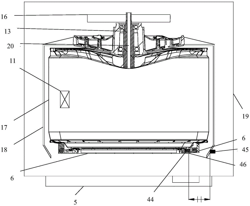
As shown in fig. 23, a control method of a washing machine includes a housing 19; an inner tub 17 for containing washing water when washing laundry; an inner barrel door 6 which is arranged on the barrel opening of the inner barrel 17 and can be opened and closed, and an inner barrel door pushing device 46 which is arranged in the shell 19 and is used for pushing the inner barrel door 6 to be closed, wherein the control method comprises the following steps: the washing machine controls the inner drum door pushing device 46 to start pushing the inner drum door 6 to close.
In this embodiment, an opening is formed on the casing 19 of the washing machine corresponding to the opening of the inner cylinder 17, a door body 5 capable of opening and closing is installed on the opening, the control system of the washing machine determines whether the door body 5 is closed, if yes, the inner cylinder door pushing device 46 is controlled to be started, and the inner cylinder door 6 is pushed to be closed; if not, the inner barrel door closing device 46 is controlled to remain closed.
In one scheme, a control program capable of controlling the inner drum door pushing device 46 to be started can be set in the control system of the washing machine, a user can start the inner drum door pushing device 46 at any time according to the need through the control program, and can selectively start the inner drum door pushing device 46 through a button/key or other modes.
In this embodiment, an electromagnetic lock is disposed on the door body 5 of the washing machine, and is used to detect whether the door body 5 of the washing machine is closed, and if yes, the control system of the washing machine controls the inner cylinder door pushing device 46 to start, and pushes the inner cylinder door 6 to close; if the detection is negative, the inner barrel door closing device 46 is controlled to be kept in a closed state and not started.
In this embodiment, a position detecting device is disposed in the outer tub 18 of the washing machine, and is used for detecting whether the inner tub door 6 is closed in place, the position detecting device includes a detected terminal 44 and a position sensor 45, the detected terminal 44 is disposed on the inner tub door 6 of the washing machine, the position sensor 45 is disposed on the inner sidewall of the outer tub 18, in this embodiment, the washing machine further includes a main controller 4, and the main controller 4 is electrically connected with the position sensor 45.
The main controller 4 of the washing machine judges whether the inner barrel door 6 is closed in place according to the signal detected by the position detection device, so that the problems of water leakage under washing or rinsing and dewatering conditions caused by the condition of non-closing or damage caused by high-speed rotation of the inner barrel door 6 which is not closed in place due to negligence of a user are avoided.
When the washing machine detects that the door body 5 is closed and locked, the position detection device detects whether the inner barrel door 6 of the washing machine is closed, and if so, the inner barrel door pushing device 46 is controlled to keep a closed state; if the detection is negative, the control system of the washing machine controls the inner barrel door pushing device 46 to start, and the inner barrel door 6 is pushed to close.
After the washing machine detects that the door body 5 is closed and locked, when the position detection device detects that the inner barrel door 6 is not closed, the inner barrel door pushing device 46 is controlled to act, the inner barrel door 6 is pushed to be closed, after each action of the inner barrel door pushing device 46, the position detection device detects that the inner barrel door 6 is not closed in place, the inner barrel door pushing device 46 is controlled to act again, the cycle is executed for N times, and when N is larger than N0 (N0 is a set value), the washing machine is suspended and alarms;
preferably, n0=3.
The position detecting device detects that the specific detecting method is that the signal value generated between the detected terminal 44 and the position sensor 45 when the inner drum door 6 is closed in place is input into the main controller 4 of the washing machine and used as the reference signal value for judging whether the inner drum door 6 is closed in place or not.
When the signal value generated between the detected terminal 44 and the position sensor 45 received by the main controller 4 of the washing machine is equal to the reference signal value, the main controller 4 of the washing machine judges that the inner barrel door 6 is closed in place and controls the washing machine to wash; when the signal value generated between the detected terminal 44 and the position sensor 45 received by the main controller 4 of the washing machine is different from the reference signal value, the main controller 4 of the washing machine judges that the inner drum door 6 is far away from the closed position, controls the washing machine to send an alarm signal to remind a user to close the inner drum door 6, and avoids the problems of water leakage under the conditions of washing or rinsing and dehydration caused by the condition of non-closing, damage caused by the condition that the door body is not closed in place and rotates at a high speed due to negligence of the user, and the like.
The eighth to tenth embodiments may be drum washing machines or pulsator washing machines, and are preferably described by taking drum washing machines as an example.
The foregoing description is only illustrative of the preferred embodiment of the present invention, and is not to be construed as limiting the invention, but is to be construed as limiting the invention to any and all simple modifications, equivalent variations and adaptations of the embodiments described above, which are within the scope of the invention, may be made by those skilled in the art without departing from the scope of the invention.