CN111663209A - Vortex tube for vortex spinning convenient to use and using method thereof - Google Patents
Vortex tube for vortex spinning convenient to use and using method thereof Download PDFInfo
- Publication number
- CN111663209A CN111663209A CN202010600434.0A CN202010600434A CN111663209A CN 111663209 A CN111663209 A CN 111663209A CN 202010600434 A CN202010600434 A CN 202010600434A CN 111663209 A CN111663209 A CN 111663209A
- Authority
- CN
- China
- Prior art keywords
- vortex
- tube
- air
- hole
- yarn
- Prior art date
- Legal status (The legal status is an assumption and is not a legal conclusion. Google has not performed a legal analysis and makes no representation as to the accuracy of the status listed.)
- Pending
Links
Images


Classifications
-
- D—TEXTILES; PAPER
- D01—NATURAL OR MAN-MADE THREADS OR FIBRES; SPINNING
- D01H—SPINNING OR TWISTING
- D01H4/00—Open-end spinning machines or arrangements for imparting twist to independently moving fibres separated from slivers; Piecing arrangements therefor; Covering endless core threads with fibres by open-end spinning techniques
- D01H4/02—Open-end spinning machines or arrangements for imparting twist to independently moving fibres separated from slivers; Piecing arrangements therefor; Covering endless core threads with fibres by open-end spinning techniques imparting twist by a fluid, e.g. air vortex
Landscapes
- Engineering & Computer Science (AREA)
- Mechanical Engineering (AREA)
- Textile Engineering (AREA)
- Spinning Or Twisting Of Yarns (AREA)
Abstract
本发明公开了一种便于使用的涡流纺纱用涡流管,包括管体,所述管体的顶部中间位置固定设置有纤维引导管,所述纤维引导管上开设有纤维导入孔,所述纤维引导管的中间位置螺纹连接有导纱针,所述导纱针的顶部固定连接有第一旋钮,所述导纱针的圆周上转动连接有圆盘,所述圆盘的一侧焊接有指针,所述纤维引导管的上表面固定设置有纵板,所述纵板的表面开设有第一滑槽,所述指针的另一端滑动设置在所述第一滑槽内。本发明还提供一种便于使用的涡流纺纱用涡流管的使用方法。本发明能够调节导纱针和锭子端部之间的距离,可调节性高,使用方便,成纱质量好,同时方便对导气孔和抽气孔的疏通面积进行单独的调整,从而方便对涡流速度的进行调整。
The invention discloses an easy-to-use vortex tube for vortex spinning. A yarn guide needle is threadedly connected to the middle position of the guide tube, a first knob is fixedly connected to the top of the yarn guide needle, a disc is rotatably connected to the circumference of the yarn guide needle, and a pointer is welded on one side of the disc. A vertical plate is fixedly arranged on the upper surface of the fiber guide tube, a first chute is provided on the surface of the vertical plate, and the other end of the pointer is slidably arranged in the first chute. The present invention also provides an easy-to-use method of using a vortex tube for vortex spinning. The invention can adjust the distance between the yarn guide needle and the end of the spindle, has high adjustability, is easy to use, and has good yarn quality, and at the same time, it is convenient to independently adjust the dredging areas of the air guide holes and the air suction holes, so as to facilitate the adjustment of the eddy current speed. to make adjustments.
Description
技术领域technical field
本发明涉及纺纱技术领域,具体为一种便于使用的涡流纺纱用涡流管及其使用方法。The invention relates to the technical field of spinning, in particular to an easy-to-use vortex tube for vortex spinning and a method for using the same.
背景技术Background technique
涡流纺是在喷气纺的基础上发展起来的,利用固定不动的涡流纺纱管,来代替高速回转的纺纱杯进行纺纱的一种新型纺纱方法。喷气涡流纺纱利用空气的旋转使长纤维向纱线的中心集聚,短线维分散包覆在外层。这种独特的生产方法不仅可以生产包芯纱,而且可以利用不同的纤维长度,收缩度等生产双重结构的纱,能纺出丰富多彩的特出纱,具有毛羽少,密度高、爽感性好,耐洗涤性好、保湿性和膨松性好的特点。Vortex spinning is developed on the basis of air-jet spinning. It is a new spinning method that uses a fixed vortex spinning tube instead of a high-speed spinning rotor for spinning. Air-jet vortex spinning uses the rotation of air to gather long fibers toward the center of the yarn, and the short fibers are dispersed and covered in the outer layer. This unique production method can not only produce core-spun yarns, but also produce double-structured yarns with different fiber lengths, shrinkages, etc., and can spin a variety of special yarns with less hairiness, high density, and good refreshment. , Good washing resistance, good moisturizing and bulking properties.
现有的涡流纺纱用涡流管还存在一些问题:在对导纱针和锭子端部之间的距离进行调节时,不方便控制调节的深度,不能对调节的深度进行掌控,同时不方便对导气孔和抽气孔的疏通面积进行单独的调整,不方便控制涡流的速度。The existing vortex tube for vortex spinning still has some problems: when adjusting the distance between the yarn guide needle and the end of the spindle, it is inconvenient to control the depth of adjustment, and it is inconvenient to control the depth of adjustment. The dredging areas of the air guide holes and the air extraction holes are adjusted separately, which is inconvenient to control the speed of the eddy current.
发明内容SUMMARY OF THE INVENTION
本发明的目的在于提供一种便于使用的涡流纺纱用涡流管及其使用方法,以解决上述背景技术中提出的问题。The purpose of the present invention is to provide an easy-to-use vortex tube for vortex spinning and a method of using the same, so as to solve the problems raised in the above-mentioned background art.
为实现上述目的,本发明提供如下技术方案:一种便于使用的涡流纺纱用涡流管,包括管体,所述管体的顶部中间位置固定设置有纤维引导管,所述纤维引导管上开设有纤维导入孔,所述纤维引导管的中间位置螺纹连接有导纱针,所述导纱针的顶部固定连接有第一旋钮,所述导纱针的圆周上转动连接有圆盘,所述圆盘的一侧焊接有指针,所述纤维引导管的上表面固定设置有纵板,所述纵板的表面开设有第一滑槽,所述指针的另一端滑动设置在所述第一滑槽内,所述第一滑槽的外侧位于所述纵板的外表面设置有刻度线,所述纤维引导管的两侧对称开设有进气孔,所述管体上开设有导气孔,所述导气孔设置在所述进气孔的外侧,所述导气孔的外侧位于所述管体的外表面固定设置有连接块,所述连接块的外表面开设有插槽,所述连接块的外侧设置有导气管,所述导气管的一侧固定设置有插块,所述插块插接在所述插槽内,所述连接块的表面螺纹连接有紧固螺栓,所述插块通过所述紧固螺栓固定设置在所述插槽内,所述导气管的内部开设有引气孔,所述引气孔与所述导气孔连通设置,所述引气孔的内部设置有隔板,所述导气管的内部位于所述引气孔的外侧开设有第二滑槽,所述隔板与所述第二滑槽滑动连接,所述隔板的顶部一侧焊接有连接杆,所述导气管的上表面开设有凹槽,所述连接杆滑动设置在所述凹槽的内部,所述连接杆的另一端螺纹连接有螺杆,所述螺杆的底端与所述凹槽的底部转动连接,所述管体与所述纤维引导管之间设置有涡流腔,所述涡流腔内设置有锭子,所述锭子的底部固定设置在所述涡流腔的底部,所述锭子的中心位置开设有出纱通道,所述出纱通道与所述管体的外侧连通设置,所述涡流腔的底部两侧对称开设有抽气孔,所述抽气孔的外侧位于所述管体上设置有调节套筒,所述调节套筒与所述管体的外表面螺纹连接,所述调节套筒的底部设置在所述抽气孔的外侧。In order to achieve the above purpose, the present invention provides the following technical solutions: an easy-to-use vortex tube for vortex spinning, comprising a tube body, a fiber guide tube is fixedly arranged at the middle position of the top of the tube body, and a fiber guide tube is provided on the fiber guide tube. There is a fiber introduction hole, a yarn guide needle is threadedly connected to the middle position of the fiber guide tube, a first knob is fixedly connected to the top of the yarn guide needle, and a disc is rotatably connected to the circumference of the yarn guide needle, and the A pointer is welded on one side of the disc, a vertical plate is fixedly arranged on the upper surface of the fiber guide tube, a first chute is opened on the surface of the vertical plate, and the other end of the pointer is slidably arranged on the first slide. In the groove, the outer side of the first chute is located on the outer surface of the vertical plate with a scale line, the two sides of the fiber guide pipe are symmetrically provided with air intake holes, and the pipe body is provided with air guide holes, so The air guide hole is arranged on the outside of the air inlet hole, and the outside of the air guide hole is located on the outer surface of the pipe body. A connection block is fixedly arranged, and a slot is opened on the outer surface of the connection block. An air duct is provided on the outside, one side of the air duct is fixedly provided with an insert block, the insert block is inserted into the slot, the surface of the connection block is threadedly connected with fastening bolts, and the insert block passes through The fastening bolt is fixedly arranged in the slot, the air guide tube is provided with an air guide hole, the air guide hole is arranged in communication with the air guide hole, and a partition plate is arranged inside the air guide hole, and the The inside of the air guide tube is located on the outside of the air guide hole and is provided with a second chute, the baffle is slidably connected to the second slot, and a connecting rod is welded on the top side of the baffle, and the The upper surface is provided with a groove, the connecting rod is slidably arranged inside the groove, the other end of the connecting rod is threadedly connected with a screw rod, and the bottom end of the screw rod is rotatably connected with the bottom of the groove, so A vortex cavity is provided between the tube body and the fiber guide tube, a spindle is arranged in the vortex cavity, the bottom of the spindle is fixedly arranged at the bottom of the vortex cavity, and the center position of the spindle is provided with a yarn outlet. The yarn outlet channel is arranged in communication with the outside of the tube body, the bottom of the vortex cavity is symmetrically provided with air suction holes on both sides, and the outside of the air suction holes is located on the tube body with an adjustment sleeve, so The adjusting sleeve is threadedly connected with the outer surface of the pipe body, and the bottom of the adjusting sleeve is arranged outside the air suction hole.
所述圆盘与所述导纱针的圆周之间设置有轴承,所述圆盘与所述导纱针通过所述轴承转动连接。A bearing is arranged between the disc and the circumference of the yarn guide needle, and the disc and the yarn guide needle are rotatably connected through the bearing.
所述纤维导入孔呈逐渐收束的圆锥形孔状。The fiber introduction hole is in the shape of a tapered conical hole.
所述插槽、所述插块和所述紧固螺栓均设置有两组,两组所述插槽、两组所述插块和两组所述紧固螺栓对称设置在所述连接块的两侧。The slots, the insert blocks and the fastening bolts are all provided with two groups, and the two groups of the slots, the two groups of the insert blocks and the two groups of the fastening bolts are symmetrically arranged on the connecting blocks. both sides.
所述螺杆的顶部焊接有第二旋钮,所述第二旋钮设置在所述凹槽的上方。A second knob is welded on the top of the screw, and the second knob is arranged above the groove.
所述导纱针的底部位于所述出纱通道的顶部的正上方。The bottom of the yarn guide needle is located just above the top of the yarn outlet channel.
所述管体的外表面对称开设有沉槽,所述沉槽的上下高度与所述抽气孔的直径相同,且所述调节套筒顶部的初始位置与所述沉槽的底部保持水平,所述调节套筒底部的初始位置与所述抽气孔的底部保持水平。The outer surface of the pipe body is symmetrically provided with a sinking groove, the upper and lower heights of the sinking groove are the same as the diameter of the air extraction hole, and the initial position of the top of the adjusting sleeve is kept horizontal with the bottom of the sinking groove, so The initial position of the bottom of the adjusting sleeve is kept horizontal with the bottom of the air suction hole.
本发明还提供一种便于使用的涡流纺纱用涡流管的使用方法,包括以下步骤:The present invention also provides an easy-to-use method for using a vortex tube for vortex spinning, comprising the following steps:
S1、在使用涡流管时,首先通过转动第一旋钮,使第一旋钮带动导纱针转动,导纱针带动指针的一端在第一滑槽内移动,并且通过观察刻度线,将指针移动到合适的位置,对导纱针与锭子端部的距离进行调节;S1. When using the vortex tube, first turn the first knob, so that the first knob drives the yarn guide needle to rotate, the yarn guide needle drives one end of the pointer to move in the first chute, and by observing the scale line, move the pointer to Adjust the distance between the yarn guide needle and the end of the spindle at the appropriate position;
S2、然后通过将插块插入插槽内,通过紧固螺栓将插块固定在插槽内,将导气管与连接块固定;S2. Then insert the insert block into the slot, fix the insert block in the slot by tightening bolts, and fix the air duct and the connection block;
S3、接着通过转动螺杆,使螺杆带动连接杆移动,连接杆带动隔板在第二滑槽内滑动,使隔板滑动到合适的位置,对引气孔的开口大小进行调节;S3. Then, by rotating the screw rod, the screw rod drives the connecting rod to move, and the connecting rod drives the partition plate to slide in the second chute, so that the partition plate slides to a suitable position, and the opening size of the air inlet hole is adjusted;
S4、其次通过转动调节套筒,使调节套筒的底部上移,将抽气孔打开,并且将抽气孔的开口调节到合适的大小;S4. Secondly, by rotating the adjusting sleeve, the bottom of the adjusting sleeve is moved up, the air extraction hole is opened, and the opening of the air extraction hole is adjusted to an appropriate size;
S5、最后在进行纺纱工作。S5. Finally, spinning is performed.
与现有技术相比,本发明的有益效果是:Compared with the prior art, the beneficial effects of the present invention are:
1、本发明通过转动第一旋钮,使第一旋钮带动导纱针转动,导纱针带动指针的一端在第一滑槽内移动,并且通过观察刻度线,将指针移动到合适的位置,对导纱针与锭子端部的距离进行调节,从而方便掌控调节的深度;1. In the present invention, by rotating the first knob, the first knob drives the yarn guide needle to rotate, and the yarn guide needle drives one end of the pointer to move in the first chute. The distance between the yarn guide needle and the end of the spindle can be adjusted, so that it is convenient to control the depth of adjustment;
2、本发明通过转动螺杆,使螺杆带动连接杆移动,连接杆带动隔板在第二滑槽内滑动,使隔板滑动到合适的位置,对引气孔的开口大小进行调节,从而调节导气孔的疏通面积,同时通过转动调节套筒,使调节套筒的底部上移,将抽气孔打开,并且将抽气孔的开口调节到合适的大小,从而调节抽气孔的疏通面积,从而方便单独的对导气孔和抽气孔的疏通面积进行调节,便于控制涡流的速度。2. In the present invention, by rotating the screw rod, the screw rod drives the connecting rod to move, and the connecting rod drives the partition plate to slide in the second chute, so that the partition plate slides to a suitable position, and the opening size of the air inlet hole is adjusted to adjust the air guide hole. At the same time, by rotating the adjustment sleeve, the bottom of the adjustment sleeve is moved up, the air extraction hole is opened, and the opening of the air extraction hole is adjusted to an appropriate size, so as to adjust the dredging area of the air extraction hole, so as to facilitate the separate adjustment of the air extraction hole. The dredging area of the air guide hole and the air extraction hole is adjusted, which is convenient to control the speed of the vortex.
附图说明Description of drawings
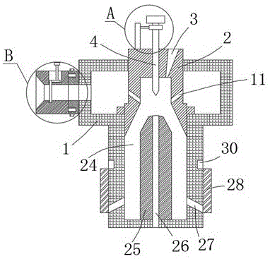
图1为本发明的结构示意图;Fig. 1 is the structural representation of the present invention;
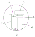
图2为本发明图1中A 处放大图;Fig. 2 is the enlarged view of A place in Fig. 1 of the present invention;
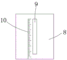
图3为本发明图2中纵板的右视结构示意图;Fig. 3 is the right side structural schematic diagram of the vertical plate in Fig. 2 of the present invention;
图4为本发明图1中B 处放大图;Fig. 4 is the enlarged view of place B in Fig. 1 of the present invention;
图5为本发明图4中C处放大图。FIG. 5 is an enlarged view of the position C in FIG. 4 of the present invention.
图中:1、管体;2、纤维引导管;3、纤维导入孔;4、导纱针;5、第一旋钮;6、圆盘;7、指针;8、纵板;9、第一滑槽;10、刻度线;11、进气孔;12、导气孔;13、连接块;14、插槽;15、导气管;16、插块;17、紧固螺栓;18、引气孔;19、隔板;20、第二滑槽;21、连接杆;22、凹槽;23、螺杆;24、涡流腔;25、锭子;26、出纱通道;27、抽气孔;28、调节套筒;29、第二旋钮;30、沉槽。In the figure: 1. Tube body; 2. Fiber guide tube; 3. Fiber introduction hole; 4. Yarn guide needle; 5. First knob; 6. Disc; 7. Pointer; 8. Vertical plate; 9. First Chute; 10, scale line; 11, air inlet; 12, air guide hole; 13, connecting block; 14, slot; 15, air guide pipe; 16, insert block; 17, fastening bolt; 18, air guide hole; 19. Partition plate; 20. Second chute; 21. Connecting rod; 22. Groove; 23. Screw; 24. Vortex cavity; 25. Spindle; Cylinder; 29, second knob; 30, sink.
具体实施方式Detailed ways
下面将结合本发明实施例中的附图,对本发明实施例中的技术方案进行清楚、完整地描述,显然,所描述的实施例仅仅是本发明一部分实施例,而不是全部的实施例。基于本发明中的实施例,本领域普通技术人员在没有做出创造性劳动前提下所获得的所有其他实施例,都属于本发明保护的范围。The technical solutions in the embodiments of the present invention will be clearly and completely described below with reference to the accompanying drawings in the embodiments of the present invention. Obviously, the described embodiments are only a part of the embodiments of the present invention, but not all of the embodiments. Based on the embodiments of the present invention, all other embodiments obtained by those of ordinary skill in the art without creative efforts shall fall within the protection scope of the present invention.
请参阅图1-5,对本发明做出以下解释:Referring to Figures 1-5, the following explanations of the present invention are made:
实施例1Example 1
一种便于使用的涡流纺纱用涡流管,包括管体1,管体1的顶部中间位置固定设置有纤维引导管2,纤维引导管2上开设有纤维导入孔3,纤维引导管2的中间位置螺纹连接有导纱针4,导纱针4的顶部固定连接有第一旋钮5,导纱针4的圆周上转动连接有圆盘6,圆盘6的一侧焊接有指针7,纤维引导管2的上表面固定设置有纵板8,纵板8的表面开设有第一滑槽9,指针7的另一端滑动设置在第一滑槽9内,第一滑槽9的外侧位于纵板8的外表面设置有刻度线10;An easy-to-use vortex tube for vortex spinning, comprising a
纤维引导管2的两侧对称开设有进气孔11,管体1上开设有导气孔12,导气孔12设置在进气孔11的外侧,导气孔12的外侧位于管体1的外表面固定设置有连接块13,连接块13的外表面开设有插槽14,连接块13的外侧设置有导气管15,导气管15的一侧固定设置有插块16,插块16插接在插槽14内,连接块13的表面螺纹连接有紧固螺栓17,插块16通过紧固螺栓17固定设置在插槽14内,导气管15的内部开设有引气孔18,引气孔18与导气孔12连通设置,引气孔18的内部设置有隔板19,导气管15的内部位于引气孔18的外侧开设有第二滑槽20,隔板19与第二滑槽20滑动连接,隔板19的顶部一侧焊接有连接杆21,导气管15的上表面开设有凹槽22,连接杆21滑动设置在凹槽22的内部,连接杆21的另一端螺纹连接有螺杆23,螺杆23的底端与凹槽22的底部转动连接;The
管体1与纤维引导管2之间设置有涡流腔24,涡流腔24内设置有锭子25,锭子25的底部固定设置在涡流腔24的底部,锭子25的中心位置开设有出纱通道26,出纱通道26与管体1的外侧连通设置,涡流腔24的底部两侧对称开设有抽气孔27,抽气孔27的外侧位于管体1上设置有调节套筒28,调节套筒28与管体1的外表面螺纹连接,调节套筒28的底部设置在抽气孔27的外侧。A
为了方便圆盘6与导纱针4转动,圆盘6与导纱针4的圆周之间设置有轴承,圆盘6与导纱针4通过轴承转动连接。In order to facilitate the rotation of the
为了方便引入纤维条,纤维导入孔3呈逐渐收束的圆锥形孔状。In order to facilitate the introduction of fiber strands, the
为了增加导气管15安装的稳定性,插槽14、插块16和紧固螺栓17均设置有两组,两组插槽14、两组插块16和两组紧固螺栓17对称设置在连接块13的两侧。In order to increase the stability of the installation of the
为了方便对螺杆23进行转动,螺杆23的顶部焊接有第二旋钮29,第二旋钮29设置在凹槽22的上方。In order to facilitate the rotation of the
为了方便产生涡流,导纱针4的底部位于出纱通道26的顶部的正上方。In order to facilitate the generation of eddy currents, the bottom of the
为了方便通过转动调节套筒28,来调节抽气孔27的开口大小,管体1的外表面对称开设有沉槽30,沉槽30的上下高度与抽气孔27的直径相同,且调节套筒28顶部的初始位置与沉槽30的底部保持水平,调节套筒28底部的初始位置与抽气孔27的底部保持水平。In order to easily adjust the opening size of the
实施例2Example 2
一种便于使用的涡流纺纱用涡流管的使用方法,包括以下步骤:An easy-to-use method for using a vortex tube for vortex spinning, comprising the following steps:
S1、在使用涡流管时,首先通过转动第一旋钮5,使第一旋钮5带动导纱针4转动,导纱针4带动指针7的一端在第一滑槽9内移动,并且通过观察刻度线10,将指针7移动到合适的位置,对导纱针4与锭子25端部的距离进行调节;S1. When using the vortex tube, firstly by rotating the
S2、然后通过将插块16插入插槽14内,通过紧固螺栓17将插块16固定在插槽14内,将导气管15与连接块13固定;S2, then insert the
S3、接着通过转动螺杆23,使螺杆23带动连接杆21移动,连接杆21带动隔板19在第二滑槽20内滑动,使隔板19滑动到合适的位置,对引气孔18的开口大小进行调节;S3. Then, by rotating the
S4、其次通过转动调节套筒28,使调节套筒28的底部上移,将抽气孔27打开,并且将抽气孔27的开口调节到合适的大小;S4, secondly, by rotating the adjusting
S5、最后在进行纺纱工作。S5. Finally, spinning is performed.
结构原理:本发明通过转动第一旋钮5,使第一旋钮5带动导纱针4转动,导纱针4带动指针7的一端在第一滑槽9内移动,并且通过观察刻度线10,将指针7移动到合适的位置,对导纱针4与锭子25端部的距离进行调节,从而方便掌控调节的深度;通过转动螺杆23,使螺杆23带动连接杆21移动,连接杆21带动隔板19在第二滑槽20内滑动,使隔板19滑动到合适的位置,对引气孔18的开口大小进行调节,从而调节导气孔12的疏通面积,同时通过转动调节套筒28,使调节套筒28的底部上移,将抽气孔27打开,并且将抽气孔27的开口调节到合适的大小,从而调节抽气孔27的疏通面积,从而方便单独的对导气孔12和抽气孔27的疏通面积进行调节,便于控制涡流的速度。Structural principle: In the present invention, by rotating the
尽管已经示出和描述了本发明的实施例,对于本领域的普通技术人员而言,可以理解在不脱离本发明的原理和精神的情况下可以对这些实施例进行多种变化、修改、替换和变型,本发明的范围由所附权利要求及其等同物限定。Although embodiments of the present invention have been shown and described, it will be understood by those skilled in the art that various changes, modifications, and substitutions can be made in these embodiments without departing from the principle and spirit of the invention and modifications, the scope of the invention is defined by the appended claims and their equivalents.
Claims (8)
Priority Applications (1)
| Application Number | Priority Date | Filing Date | Title |
|---|---|---|---|
| CN202010600434.0A CN111663209A (en) | 2020-06-29 | 2020-06-29 | Vortex tube for vortex spinning convenient to use and using method thereof |
Applications Claiming Priority (1)
| Application Number | Priority Date | Filing Date | Title |
|---|---|---|---|
| CN202010600434.0A CN111663209A (en) | 2020-06-29 | 2020-06-29 | Vortex tube for vortex spinning convenient to use and using method thereof |
Publications (1)
| Publication Number | Publication Date |
|---|---|
| CN111663209A true CN111663209A (en) | 2020-09-15 |
Family
ID=72390140
Family Applications (1)
| Application Number | Title | Priority Date | Filing Date |
|---|---|---|---|
| CN202010600434.0A Pending CN111663209A (en) | 2020-06-29 | 2020-06-29 | Vortex tube for vortex spinning convenient to use and using method thereof |
Country Status (1)
| Country | Link |
|---|---|
| CN (1) | CN111663209A (en) |
Citations (7)
| Publication number | Priority date | Publication date | Assignee | Title |
|---|---|---|---|---|
| CN106400225A (en) * | 2016-06-22 | 2017-02-15 | 陕西宝成航空仪表有限责任公司 | Detection device for needle length and spindle height of air-jetting vortex spinning machine |
| CN205974798U (en) * | 2016-06-13 | 2017-02-22 | 福建省长乐市锦源纺织有限公司 | Vortex spinning machine is with spinning pipe with adjustable |
| CN108517590A (en) * | 2018-06-16 | 2018-09-11 | 苏州市星京泽纤维科技有限公司 | A kind of New Vortex used in spinning machine textile tubes |
| CN109357061A (en) * | 2018-12-11 | 2019-02-19 | 雷纳德流体智能科技江苏股份有限公司 | A kind of Novel direct streaming shut-off valve of regulating flow quantity |
| CN209323055U (en) * | 2018-11-28 | 2019-08-30 | 苏州市星京泽纤维科技有限公司 | Air intake adjustable vortex tube for vortex spinning machine |
| CN111120722A (en) * | 2020-03-04 | 2020-05-08 | 德维阀门铸造(苏州)股份有限公司 | A pneumatic connection throttle valve indicating mechanism |
| CN212357486U (en) * | 2020-06-29 | 2021-01-15 | 江苏京正特种纤维有限公司 | Vortex tube for vortex spinning convenient to use |
-
2020
- 2020-06-29 CN CN202010600434.0A patent/CN111663209A/en active Pending
Patent Citations (7)
| Publication number | Priority date | Publication date | Assignee | Title |
|---|---|---|---|---|
| CN205974798U (en) * | 2016-06-13 | 2017-02-22 | 福建省长乐市锦源纺织有限公司 | Vortex spinning machine is with spinning pipe with adjustable |
| CN106400225A (en) * | 2016-06-22 | 2017-02-15 | 陕西宝成航空仪表有限责任公司 | Detection device for needle length and spindle height of air-jetting vortex spinning machine |
| CN108517590A (en) * | 2018-06-16 | 2018-09-11 | 苏州市星京泽纤维科技有限公司 | A kind of New Vortex used in spinning machine textile tubes |
| CN209323055U (en) * | 2018-11-28 | 2019-08-30 | 苏州市星京泽纤维科技有限公司 | Air intake adjustable vortex tube for vortex spinning machine |
| CN109357061A (en) * | 2018-12-11 | 2019-02-19 | 雷纳德流体智能科技江苏股份有限公司 | A kind of Novel direct streaming shut-off valve of regulating flow quantity |
| CN111120722A (en) * | 2020-03-04 | 2020-05-08 | 德维阀门铸造(苏州)股份有限公司 | A pneumatic connection throttle valve indicating mechanism |
| CN212357486U (en) * | 2020-06-29 | 2021-01-15 | 江苏京正特种纤维有限公司 | Vortex tube for vortex spinning convenient to use |
Similar Documents
| Publication | Publication Date | Title |
|---|---|---|
| CN103409861B (en) | A kind of centrifugal Static Spinning nanometer is twisted thread high speed preparation facilities and technique | |
| CN204491055U (en) | A kind of spout cyclone type is prepared nanometer and to be twisted thread electrostatic spinning nozzle device | |
| CN103603095B (en) | The configuration structure in jet-impingement hole in a kind of air injection air vortex spinning apparatus | |
| CN106480523A (en) | Acid fiber by polylactic high-speed spinning processes | |
| CN104088045B (en) | A kind of ring spun yarn in negative pressure airflow suction mode Siro-spinning method and apparatus | |
| CN108517590A (en) | A kind of New Vortex used in spinning machine textile tubes | |
| CN111663209A (en) | Vortex tube for vortex spinning convenient to use and using method thereof | |
| CN212357486U (en) | Vortex tube for vortex spinning convenient to use | |
| CN111691026A (en) | Yarn guide device for vortex spinning and use method thereof | |
| CN209323055U (en) | Air intake adjustable vortex tube for vortex spinning machine | |
| CN208562640U (en) | A kind of New Vortex used in spinning machine textile tubes | |
| CN209227131U (en) | Vortex spinning machine and its multi-power adjustable spinning tube | |
| CN207650022U (en) | A kind of vortex spinning yarn processing tensile property test device | |
| CN103305979B (en) | The groove-shaped low fine hollow ingot of a kind of air-jet eddy-current spinning | |
| CN216947336U (en) | Yarn guide device for vortex spinning | |
| CN203462202U (en) | Adjustable impurity suctioning device used for carding cavity of rotor spinning machine | |
| CN111155215A (en) | Spinning process and spinning device for feeding three rovings | |
| CN2273731Y (en) | Air cushion pressure headbox | |
| CN216295795U (en) | Membrane aperture test equipment | |
| CN213327992U (en) | An air intake adjustable vortex tube for a vortex spinning machine | |
| CN222524916U (en) | Untwisting pipe | |
| CN217837905U (en) | Yarn guide structure for textile machine | |
| CN209211012U (en) | Dislocation type network nozzle oiling device for polyester filament | |
| CN209883047U (en) | Guide wire tongue gel filling device | |
| CN112267184A (en) | A kind of fast positioning device for core-spun yarn godet |
Legal Events
| Date | Code | Title | Description |
|---|---|---|---|
| PB01 | Publication | ||
| PB01 | Publication | ||
| SE01 | Entry into force of request for substantive examination | ||
| SE01 | Entry into force of request for substantive examination | ||
| WD01 | Invention patent application deemed withdrawn after publication | ||
| WD01 | Invention patent application deemed withdrawn after publication |
Application publication date: 20200915 |