CN111644499A - Automatic punch forming mechanism for industrial production - Google Patents
Automatic punch forming mechanism for industrial production Download PDFInfo
- Publication number
- CN111644499A CN111644499A CN202010534907.1A CN202010534907A CN111644499A CN 111644499 A CN111644499 A CN 111644499A CN 202010534907 A CN202010534907 A CN 202010534907A CN 111644499 A CN111644499 A CN 111644499A
- Authority
- CN
- China
- Prior art keywords
- workbench
- hydraulic cylinder
- forming mechanism
- industrial production
- ball screw
- Prior art date
- Legal status (The legal status is an assumption and is not a legal conclusion. Google has not performed a legal analysis and makes no representation as to the accuracy of the status listed.)
- Pending
Links
Images


Classifications
-
- B—PERFORMING OPERATIONS; TRANSPORTING
- B21—MECHANICAL METAL-WORKING WITHOUT ESSENTIALLY REMOVING MATERIAL; PUNCHING METAL
- B21D—WORKING OR PROCESSING OF SHEET METAL OR METAL TUBES, RODS OR PROFILES WITHOUT ESSENTIALLY REMOVING MATERIAL; PUNCHING METAL
- B21D22/00—Shaping without cutting, by stamping, spinning, or deep-drawing
- B21D22/02—Stamping using rigid devices or tools
-
- B—PERFORMING OPERATIONS; TRANSPORTING
- B21—MECHANICAL METAL-WORKING WITHOUT ESSENTIALLY REMOVING MATERIAL; PUNCHING METAL
- B21D—WORKING OR PROCESSING OF SHEET METAL OR METAL TUBES, RODS OR PROFILES WITHOUT ESSENTIALLY REMOVING MATERIAL; PUNCHING METAL
- B21D37/00—Tools as parts of machines covered by this subclass
- B21D37/04—Movable or exchangeable mountings for tools
Abstract
The invention discloses an automatic punch forming mechanism for industrial production, which comprises a workbench, wherein a die is fixedly arranged on the workbench, a hydraulic cylinder is arranged right above the mould, the central line of the telescopic rod of the hydraulic cylinder and the central line of the mould are positioned on a vertical straight line, two guide rods and a ball screw are arranged between the telescopic rod of the hydraulic cylinder and the mould, the two guide rods and the ball screw are parallel to each other, the guide rods are fixedly arranged on the workbench and are parallel to the workbench, the two guide rods are provided with sliding bodies, the sliding body moves along the length direction of the guide rod, the nut seat of the ball screw is fixedly connected with the side surface of the sliding body, one end of the ball screw is fixedly installed on the workbench through a bearing seat, the other end of the ball screw is fixedly connected with a rotating shaft of the servo motor through a coupler, and the servo motor is fixedly installed on the workbench through a motor installation support. The stamping mechanism has the advantages of simple structural design, low modification cost and small difficulty, and is suitable for large-scale popularization on the basis of the existing stamping mechanism.
Description
Technical Field
The invention relates to the field of workpiece stamping equipment, in particular to an automatic stamping forming mechanism for industrial production.
Background
The stamping is a forming method in which a press and a die are used to apply external force to a plate, a strip, a pipe, a profile, etc. to cause plastic deformation or separation, thereby obtaining a workpiece (stamped part) of a desired shape and size. Stamping and forging are plastic working (or called pressure working), and are called forging and pressing. The stamped blanks are mainly hot and cold rolled steel sheets and strips. In the world, 60-70% of steel materials are plates, and most of the plates are punched to form finished products. In the stamping process of the traditional stamping machine, only one type and specification of stamping part can be stamped, so that the use efficiency of stamping equipment is seriously wasted.
However, when the existing punching and pressing mechanism is used for processing punching parts (such as circular steel sheets with different areas) with different sizes, the punching head needs to be replaced manually, the operation is troublesome, and the punching efficiency is low.
Disclosure of Invention
The invention aims to solve the problems and designs an automatic punch forming mechanism for industrial production.
The technical scheme of the invention is that the automatic punch forming mechanism for industrial production comprises a workbench, a mould is fixedly arranged on the workbench, a hydraulic cylinder is arranged right above the mould, the central line of a telescopic rod of the hydraulic cylinder and the central line of the mould are positioned on a vertical straight line,
two guide rods and a ball screw are arranged between the telescopic rod of the hydraulic cylinder and the die, the two guide rods and the ball screw are parallel to each other, the guide rods are fixedly arranged on the workbench and are parallel to the workbench, sliding bodies are arranged on the two guide rods and move along the length direction of the guide rods, nut seats of the ball screw are fixedly connected with the side surface of the sliding bodies, one end of the ball screw is fixedly arranged on the workbench through a bearing seat, the other end of the ball screw is fixedly connected with a rotating shaft of a servo motor through a coupler, and the servo motor is fixedly arranged on the workbench through a motor mounting bracket;
the utility model discloses a slide structure, including the slider, the slider is provided with a plurality of through-holes, the through-hole is cylindrical hole, the upper and lower surface of through-hole intercommunication slider, a plurality of through-holes are arranged on a straight line along the length direction equidistance of guide bar, the lower extreme port department of through-hole is equipped with the flange, be equipped with down the depression bar in the through-hole, the border fixed connection baffle ring of lower depression bar up end, the lower extreme of depression bar passes the flange of port under the through-hole and stretches out the slider lower surface down, the lower extreme of depression bar passes through ring flange fixed connection punching press head down, the cover has the spring down on the depression bar, the one end of spring and the lower fixed surface of baffle ring are connected.
The central lines of the through holes and the central line of the hydraulic cylinder telescopic rod are parallel to each other and are positioned in the same vertical plane.
The central line of the lower pressure rod is superposed with the central line of the through hole.
The central line of the lower pressure lever is vertical to the length direction of the guide rod.
The diameter of the flange plate at the lower end of the lower pressing rod is larger than that of the port at the lower end of the through hole.
The sliding body is of a cuboid structure made of aluminum alloy materials.
The two ends of the guide rod are fixedly arranged on the workbench through the supporting seat.
The lower end face of the telescopic rod of the hydraulic cylinder is a spherical face, a groove is machined in the center of the upper end face of the lower pressing rod and is a hemispherical groove, and the shape and the position of the groove correspond to the end face of the lower end of the telescopic rod of the hydraulic cylinder.
And a rubber cushion pad is fixedly arranged in the groove.
The hydraulic cylinder is fixedly arranged on the workbench through a support.
Advantageous effects
The automatic punch forming mechanism for industrial production manufactured by the technical scheme of the invention has the following advantages:
1. the mechanism drives the sliding body to move along the guide rod through the servo motor, the through holes under the telescopic rod of the hydraulic cylinder are switched through the equidistant movement of the sliding body, and the lower pressing rods in different through holes move to the positions under the telescopic rod of the hydraulic cylinder according to requirements, so that the technical effect of automatically switching the size and the shape of the stamping head is realized, manual operation is not needed in the process of switching the stamping head, the working strength is effectively reduced, the time is saved, and the production efficiency is improved;
2. on the basis of the existing punching mechanism, the mechanism only increases the structures of the guide rod, the ball screw, the sliding body, the lower pressing rod and the spring, does not change the existing punching structure greatly, is very small in the improvement cost and the improvement difficulty, and is suitable for large-scale popularization.
Drawings
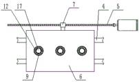
FIG. 1 is a schematic structural view of an automatic press molding mechanism for industrial production according to the present invention;
FIG. 2 is a schematic view of the structure of the slider, guide rod and ball screw according to the present invention;
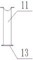
FIG. 3 is a schematic view of the structure of the push-down lever of the present invention;
FIG. 4 is a schematic structural view of an automatic press molding mechanism for industrial production according to the present invention;
in the figure, 1, a workbench; 2. a mold; 3. a hydraulic cylinder telescopic rod; 4. a guide bar; 5. a ball screw; 6. a sliding body; 7. a nut seat; 8. a bearing seat; 9. a through hole; 10. blocking edges; 11. a lower pressure lever; 12. a baffle ring; 13. a flange plate; 14. punching a head; 15. a spring; 16. a supporting seat; 17. a rubber cushion pad; 18. a hydraulic cylinder bracket; 19. a servo motor; 20. a coupling is provided.
Detailed Description
The invention is described in detail with reference to the accompanying drawings, as shown in fig. 1-4, the invention is characterized in that two guide rods 4 and a ball screw 5 are arranged between a telescopic rod of a hydraulic cylinder and a mold, the two guide rods and the ball screw are parallel to each other, the guide rods are fixedly arranged on a workbench and parallel to the workbench, a sliding body 6 is arranged on the two guide rods, the sliding body moves along the length direction of the guide rods, a nut seat 7 of the ball screw is fixedly connected with the side surface of the sliding body, one end of the ball screw is fixedly arranged on the workbench through a bearing seat 8, the other end of the ball screw is fixedly connected with a rotating shaft of a servo motor 17 through a coupling 20, and the servo motor is fixedly arranged on the workbench through a motor mounting bracket; the utility model discloses a slide structure, including the slider, the slider processes a plurality of through-holes 9, the through-hole is cylindrical hole, the upper and lower surface of through-hole intercommunication slider, a plurality of through-holes are arranged on a straight line along the length direction equidistance of guide bar, the lower extreme port department of through-hole is equipped with flange 10, be equipped with depression bar 11 in the through-hole, the outside of depression bar up end is along fixed connection retainer ring 12, the lower extreme of depression bar passes the flange of port under the through-hole and stretches out the slider lower surface, the lower extreme of depression bar passes flange 13 fixed connection punching press head 14 down, the cover has spring 15 on the depression bar down, the one end of spring and the fixed surface of retainer ring are connected, the other end of spring and the last fixed.
The hydraulic cylinder is characterized in that the central lines of the through holes and the central line of the hydraulic cylinder telescopic rod are parallel to each other and are positioned in the same vertical plane; the central line of the lower pressure rod is superposed with the central line of the through hole; the central line of the lower pressure lever is vertical to the length direction of the guide rod; the diameter of the flange plate at the lower end of the lower pressing rod is larger than that of the port at the lower end of the through hole; the sliding body is of a cuboid structure made of aluminum alloy materials; two ends of the guide rod are fixedly arranged on the workbench through a supporting seat 16; the lower end face of the telescopic rod of the hydraulic cylinder is a spherical surface, a groove is machined in the center of the upper end face of the lower pressing rod and is a hemispherical groove, and the shape and the position of the groove correspond to the end face of the lower end of the telescopic rod of the hydraulic cylinder; a rubber buffer cushion 17 is fixedly arranged in the groove; the hydraulic cylinder is fixedly arranged on the workbench through a support.
The electronic device adopted by the technical scheme comprises:
a hydraulic cylinder and a controller and a hydraulic system matched with the hydraulic cylinder;
a servo motor and a controller thereof;
the electronic devices are all conventional products, and the structure of the electronic device is not specially required or changed;
in the implementation process of the technical scheme, a person in the art needs to connect all the electrical components in the present application with a power supply adapted to the electrical components through a wire, and should select an appropriate controller according to actual conditions to meet control requirements, and specific connection and control sequence.
In the technical scheme, the working parameters of the servo motor are set through the servo motor controller, so that the servo motor drives the nut seat to move for one section, and each section of the nut seat moves for the same displacement. When the stamping head needs to be switched, a worker controls the servo motor to drive the sliding body to slide on the guide rod by one section through the servo motor controller, the servo motor controller drives the nut seat to drive the sliding body to move by one section of the same displacement every time, and a lower pressing rod just moves to the position under the telescopic rod of the hydraulic cylinder after the displacement of each section is completed. Through the control moving mode, the worker moves the needed stamping head to the position under the telescopic rod of the hydraulic cylinder, then the hydraulic cylinder is started, the telescopic rod of the hydraulic cylinder vertically downwards strikes the rubber cushion pad in the groove of the upper surface of the lower pressing rod at the moment, and then the lower pressing rod is pushed to drive the stamping head impact die at the lower end of the lower pressing rod, so that stamping work is completed.
In the technical scheme of the application, a hydraulic system of the hydraulic cylinder is arranged in a workbench, the outer diameter of a baffle ring at the upper end of a lower pressure rod is matched with the inner diameter of a through hole, and the diameter of the lower pressure rod is matched with the inner diameter of a baffle edge at the lower end of the through hole; and lubricating oil is smeared on the inner surface of the through hole.
It is noted that, herein, relational terms such as first and second, and the like may be used solely to distinguish one entity or action from another entity or action without necessarily requiring or implying any actual such relationship or order between such entities or actions. Also, the terms "comprises," "comprising," or any other variation thereof, are intended to cover a non-exclusive inclusion, such that a process, method, article, or apparatus that comprises a list of elements does not include only those elements but may include other elements not expressly listed or inherent to such process, method, article, or apparatus. Without further limitation. The use of the phrase "comprising one of the elements does not exclude the presence of other like elements in the process, method, article, or apparatus that comprises the element.
The technical solutions described above only represent the preferred technical solutions of the present invention, and some possible modifications to some parts of the technical solutions by those skilled in the art all represent the principles of the present invention, and fall within the protection scope of the present invention.
Claims (10)
1. An automatic punch forming mechanism for industrial production comprises a workbench (1), a die (2) is fixedly installed on the workbench, a hydraulic cylinder is arranged right above the die and passes through a hydraulic cylinder bracket (18), the central line of a telescopic rod (3) of the hydraulic cylinder and the central line of the die are positioned on a vertical straight line, and the automatic punch forming mechanism is characterized in that,
two guide rods (4) and a ball screw (5) are arranged between the telescopic rod of the hydraulic cylinder and the mold, the two guide rods and the ball screw are parallel to each other, the guide rods are fixedly arranged on the workbench and are parallel to the workbench, sliding bodies (6) are arranged on the two guide rods and move along the length direction of the guide rods, nut seats (7) of the ball screw are fixedly connected with the side surfaces of the sliding bodies, one end of the ball screw is fixedly arranged on the workbench through a bearing seat (8), the other end of the ball screw is fixedly connected with a rotating shaft of a servo motor (19) through a coupling (20), and the servo motor is fixedly arranged on the workbench through a motor mounting bracket;
the utility model discloses a slide structure, including slide body, through-hole intercommunication slide body, a plurality of through-holes are arranged on a straight line along the length direction equidistance of guide bar, the lower extreme port department of through-hole is equipped with flange (10), be equipped with depression bar (11) down in the through-hole, the outer border fixed connection baffle ring (12) of depression bar up end down, the lower extreme of depression bar passes the flange of port under the through-hole and stretches out the slide body lower surface, the lower extreme of depression bar passes through ring flange (13) fixed connection punching press head (14) down, the cover has spring (15) on the depression bar down, the one end of spring and the lower fixed surface of baffle ring are connected, the other end of spring and the last fixed surface of flange are connected.
2. The automatic punch forming mechanism for industrial production according to claim 1, wherein the center lines of the plurality of through holes and the center line of the telescopic rod of the hydraulic cylinder are parallel to each other and are located in the same vertical plane.
3. The automatic press forming mechanism for industrial production according to claim 1, wherein a center line of the down-pressing lever coincides with a center line of the through-hole.
4. The automatic punch forming mechanism for industrial production according to claim 1, wherein the center line of the down-pressure rod is perpendicular to the length direction of the guide rod.
5. The automatic punch forming mechanism for industrial production according to claim 1, wherein the diameter of the flange plate at the lower end of the lower pressing rod is larger than the diameter of the port at the lower end of the through hole.
6. The automatic punch forming mechanism for industrial production according to claim 1, wherein the sliding body is a rectangular parallelepiped structure made of an aluminum alloy material.
7. The automatic press forming mechanism for industrial production according to claim 1, wherein both ends of the guide bar are fixedly mounted on the worktable through a support base (16).
8. The automatic punch forming mechanism for industrial production according to claim 1, wherein the lower end face of the hydraulic cylinder telescopic rod is a spherical face, a groove is machined in the center of the upper end face of the lower pressing rod, the groove is a hemispherical groove, and the shape and the position of the groove correspond to the end face of the lower end of the hydraulic cylinder telescopic rod.
9. The automatic press forming mechanism for industrial production according to claim 1, wherein a rubber cushion (17) is fixedly installed in the groove.
10. The automatic press forming mechanism for industrial production according to claim 1, wherein the hydraulic cylinder is fixedly mounted on the work table through a bracket.
Priority Applications (1)
| Application Number | Priority Date | Filing Date | Title |
|---|---|---|---|
| CN202010534907.1A CN111644499A (en) | 2020-06-12 | 2020-06-12 | Automatic punch forming mechanism for industrial production |
Applications Claiming Priority (1)
| Application Number | Priority Date | Filing Date | Title |
|---|---|---|---|
| CN202010534907.1A CN111644499A (en) | 2020-06-12 | 2020-06-12 | Automatic punch forming mechanism for industrial production |
Publications (1)
| Publication Number | Publication Date |
|---|---|
| CN111644499A true CN111644499A (en) | 2020-09-11 |
Family
ID=72343610
Family Applications (1)
| Application Number | Title | Priority Date | Filing Date |
|---|---|---|---|
| CN202010534907.1A Pending CN111644499A (en) | 2020-06-12 | 2020-06-12 | Automatic punch forming mechanism for industrial production |
Country Status (1)
| Country | Link |
|---|---|
| CN (1) | CN111644499A (en) |
Cited By (1)
| Publication number | Priority date | Publication date | Assignee | Title |
|---|---|---|---|---|
| CN116713372A (en) * | 2023-07-18 | 2023-09-08 | 杭州顺豪金属制品有限公司 | Forming process and forming device for pressure gauge shell |
Citations (6)
| Publication number | Priority date | Publication date | Assignee | Title |
|---|---|---|---|---|
| US2851081A (en) * | 1954-05-28 | 1958-09-09 | Western Electric Co | Device for forming resilient articles while in a flexed condition |
| AU2002338282A1 (en) * | 2001-03-29 | 2002-10-15 | Amada America, Inc. | Apparatus and programmable method for punching |
| CN105491802A (en) * | 2015-12-31 | 2016-04-13 | 深圳市鑫美威自动化设备有限公司 | Multi-head automatic switching type stamping and mounting system |
| CN208410469U (en) * | 2018-04-25 | 2019-01-22 | 黄山全晟密封科技有限公司 | A kind of diaphragm of rubber piece stamping device |
| CN208758426U (en) * | 2018-08-10 | 2019-04-19 | 青岛云东来工贸有限公司 | A kind of production truck crossbeam punching machine |
| CN210253804U (en) * | 2019-06-27 | 2020-04-07 | 李小强 | Aluminum cover punching device for lamp panel processing |
-
2020
- 2020-06-12 CN CN202010534907.1A patent/CN111644499A/en active Pending
Patent Citations (6)
| Publication number | Priority date | Publication date | Assignee | Title |
|---|---|---|---|---|
| US2851081A (en) * | 1954-05-28 | 1958-09-09 | Western Electric Co | Device for forming resilient articles while in a flexed condition |
| AU2002338282A1 (en) * | 2001-03-29 | 2002-10-15 | Amada America, Inc. | Apparatus and programmable method for punching |
| CN105491802A (en) * | 2015-12-31 | 2016-04-13 | 深圳市鑫美威自动化设备有限公司 | Multi-head automatic switching type stamping and mounting system |
| CN208410469U (en) * | 2018-04-25 | 2019-01-22 | 黄山全晟密封科技有限公司 | A kind of diaphragm of rubber piece stamping device |
| CN208758426U (en) * | 2018-08-10 | 2019-04-19 | 青岛云东来工贸有限公司 | A kind of production truck crossbeam punching machine |
| CN210253804U (en) * | 2019-06-27 | 2020-04-07 | 李小强 | Aluminum cover punching device for lamp panel processing |
Cited By (2)
| Publication number | Priority date | Publication date | Assignee | Title |
|---|---|---|---|---|
| CN116713372A (en) * | 2023-07-18 | 2023-09-08 | 杭州顺豪金属制品有限公司 | Forming process and forming device for pressure gauge shell |
| CN116713372B (en) * | 2023-07-18 | 2024-04-05 | 杭州顺豪金属制品有限公司 | Forming process and forming device for pressure gauge shell |
Similar Documents
| Publication | Publication Date | Title |
|---|---|---|
| CN2850749Y (en) | Automatic flanging machine for stamping | |
| CN112371858A (en) | Vertical rotatory multistation plate stamping forming anchor clamps | |
| CN201026670Y (en) | Aluminium alloyed door/window profile press machine | |
| CN210907584U (en) | Auxiliary stabilizing device in automobile part stamping mechanism | |
| CN101623731B (en) | Stamping method for numerical control stamping machine tool | |
| CN205587541U (en) | Punch press installation mould goes up and down to use device | |
| CN111644499A (en) | Automatic punch forming mechanism for industrial production | |
| CN201201152Y (en) | In-mold tapping machine | |
| CN205436782U (en) | Take stamping die of manipulator | |
| CN219464489U (en) | Stamping die for cold stamping | |
| CN208527844U (en) | A kind of stamping die with Anti-blockage function | |
| CN213256593U (en) | Continuous stamping device | |
| CN211539225U (en) | Stamping die of refrigerator sheet metal part | |
| CN202893943U (en) | Sheet stamping device | |
| CN112775342A (en) | Thin-wall product profiling and shaping integrated machining tool and method | |
| CN201231289Y (en) | Die device and numerical control stamping machine tool | |
| CN218361638U (en) | Auxiliary structure of stamping die | |
| CN110918759A (en) | Adjustable punching device for arc-shaped workpiece | |
| CN211330964U (en) | Automobile punching part cambered surface forming device | |
| CN220426533U (en) | Stamping die for stamping metal products | |
| CN2592303Y (en) | Small-sized digital control turret punch press | |
| CN219853129U (en) | Large R angle forming and processing device for metal parts on engineering machinery cab | |
| CN109333064B (en) | Automatic shaft sleeve processing equipment | |
| CN216501913U (en) | High-precision metal piece stamping continuous die | |
| CN217070413U (en) | Hole flanging takes side cut-out press |
Legal Events
| Date | Code | Title | Description |
|---|---|---|---|
| PB01 | Publication | ||
| PB01 | Publication | ||
| SE01 | Entry into force of request for substantive examination | ||
| SE01 | Entry into force of request for substantive examination | ||
| RJ01 | Rejection of invention patent application after publication |
Application publication date: 20200911 |
|
| RJ01 | Rejection of invention patent application after publication |