CN1116331A - Full travel, sealed, fully backlighted keyboard - Google Patents
Full travel, sealed, fully backlighted keyboard Download PDFInfo
- Publication number
- CN1116331A CN1116331A CN95106643A CN95106643A CN1116331A CN 1116331 A CN1116331 A CN 1116331A CN 95106643 A CN95106643 A CN 95106643A CN 95106643 A CN95106643 A CN 95106643A CN 1116331 A CN1116331 A CN 1116331A
- Authority
- CN
- China
- Prior art keywords
- button
- mound
- arch
- barrier film
- circuit board
- Prior art date
- Legal status (The legal status is an assumption and is not a legal conclusion. Google has not performed a legal analysis and makes no representation as to the accuracy of the status listed.)
- Pending
Links
Images


Classifications
-
- H—ELECTRICITY
- H01—ELECTRIC ELEMENTS
- H01H—ELECTRIC SWITCHES; RELAYS; SELECTORS; EMERGENCY PROTECTIVE DEVICES
- H01H13/00—Switches having rectilinearly-movable operating part or parts adapted for pushing or pulling in one direction only, e.g. push-button switch
- H01H13/70—Switches having rectilinearly-movable operating part or parts adapted for pushing or pulling in one direction only, e.g. push-button switch having a plurality of operating members associated with different sets of contacts, e.g. keyboard
- H01H13/702—Switches having rectilinearly-movable operating part or parts adapted for pushing or pulling in one direction only, e.g. push-button switch having a plurality of operating members associated with different sets of contacts, e.g. keyboard with contacts carried by or formed from layers in a multilayer structure, e.g. membrane switches
- H01H13/705—Switches having rectilinearly-movable operating part or parts adapted for pushing or pulling in one direction only, e.g. push-button switch having a plurality of operating members associated with different sets of contacts, e.g. keyboard with contacts carried by or formed from layers in a multilayer structure, e.g. membrane switches characterised by construction, mounting or arrangement of operating parts, e.g. push-buttons or keys
-
- G—PHYSICS
- G05—CONTROLLING; REGULATING
- G05G—CONTROL DEVICES OR SYSTEMS INSOFAR AS CHARACTERISED BY MECHANICAL FEATURES ONLY
- G05G1/00—Controlling members, e.g. knobs or handles; Assemblies or arrangements thereof; Indicating position of controlling members
-
- H—ELECTRICITY
- H01—ELECTRIC ELEMENTS
- H01H—ELECTRIC SWITCHES; RELAYS; SELECTORS; EMERGENCY PROTECTIVE DEVICES
- H01H2215/00—Tactile feedback
- H01H2215/002—Longer travel
-
- H—ELECTRICITY
- H01—ELECTRIC ELEMENTS
- H01H—ELECTRIC SWITCHES; RELAYS; SELECTORS; EMERGENCY PROTECTIVE DEVICES
- H01H2215/00—Tactile feedback
- H01H2215/004—Collapsible dome or bubble
- H01H2215/008—Part of substrate or membrane
-
- H—ELECTRICITY
- H01—ELECTRIC ELEMENTS
- H01H—ELECTRIC SWITCHES; RELAYS; SELECTORS; EMERGENCY PROTECTIVE DEVICES
- H01H2217/00—Facilitation of operation; Human engineering
- H01H2217/004—Larger or different actuating area
-
- H—ELECTRICITY
- H01—ELECTRIC ELEMENTS
- H01H—ELECTRIC SWITCHES; RELAYS; SELECTORS; EMERGENCY PROTECTIVE DEVICES
- H01H2219/00—Legends
- H01H2219/002—Legends replaceable; adaptable
- H01H2219/014—LED
-
- H—ELECTRICITY
- H01—ELECTRIC ELEMENTS
- H01H—ELECTRIC SWITCHES; RELAYS; SELECTORS; EMERGENCY PROTECTIVE DEVICES
- H01H2219/00—Legends
- H01H2219/054—Optical elements
- H01H2219/062—Light conductor
-
- H—ELECTRICITY
- H01—ELECTRIC ELEMENTS
- H01H—ELECTRIC SWITCHES; RELAYS; SELECTORS; EMERGENCY PROTECTIVE DEVICES
- H01H2219/00—Legends
- H01H2219/054—Optical elements
- H01H2219/066—Lens
-
- H—ELECTRICITY
- H01—ELECTRIC ELEMENTS
- H01H—ELECTRIC SWITCHES; RELAYS; SELECTORS; EMERGENCY PROTECTIVE DEVICES
- H01H2221/00—Actuators
- H01H2221/058—Actuators to avoid tilting or skewing of contact area or actuator
-
- H—ELECTRICITY
- H01—ELECTRIC ELEMENTS
- H01H—ELECTRIC SWITCHES; RELAYS; SELECTORS; EMERGENCY PROTECTIVE DEVICES
- H01H2221/00—Actuators
- H01H2221/066—Actuators replaceable
-
- H—ELECTRICITY
- H01—ELECTRIC ELEMENTS
- H01H—ELECTRIC SWITCHES; RELAYS; SELECTORS; EMERGENCY PROTECTIVE DEVICES
- H01H2221/00—Actuators
- H01H2221/07—Actuators transparent
-
- H—ELECTRICITY
- H01—ELECTRIC ELEMENTS
- H01H—ELECTRIC SWITCHES; RELAYS; SELECTORS; EMERGENCY PROTECTIVE DEVICES
- H01H2223/00—Casings
- H01H2223/002—Casings sealed
-
- H—ELECTRICITY
- H01—ELECTRIC ELEMENTS
- H01H—ELECTRIC SWITCHES; RELAYS; SELECTORS; EMERGENCY PROTECTIVE DEVICES
- H01H2223/00—Casings
- H01H2223/002—Casings sealed
- H01H2223/004—Evacuation of penetrating liquid
-
- H—ELECTRICITY
- H01—ELECTRIC ELEMENTS
- H01H—ELECTRIC SWITCHES; RELAYS; SELECTORS; EMERGENCY PROTECTIVE DEVICES
- H01H2223/00—Casings
- H01H2223/01—Mounting on appliance
- H01H2223/012—Snap mounting
-
- H—ELECTRICITY
- H01—ELECTRIC ELEMENTS
- H01H—ELECTRIC SWITCHES; RELAYS; SELECTORS; EMERGENCY PROTECTIVE DEVICES
- H01H2223/00—Casings
- H01H2223/01—Mounting on appliance
- H01H2223/014—Mounting on appliance located in recess
-
- H—ELECTRICITY
- H01—ELECTRIC ELEMENTS
- H01H—ELECTRIC SWITCHES; RELAYS; SELECTORS; EMERGENCY PROTECTIVE DEVICES
- H01H2227/00—Dimensions; Characteristics
- H01H2227/022—Collapsable dome
-
- H—ELECTRICITY
- H01—ELECTRIC ELEMENTS
- H01H—ELECTRIC SWITCHES; RELAYS; SELECTORS; EMERGENCY PROTECTIVE DEVICES
- H01H2229/00—Manufacturing
- H01H2229/042—Snap coupling; Snap mounting
-
- H—ELECTRICITY
- H01—ELECTRIC ELEMENTS
- H01H—ELECTRIC SWITCHES; RELAYS; SELECTORS; EMERGENCY PROTECTIVE DEVICES
- H01H2229/00—Manufacturing
- H01H2229/062—Maintenance or repair facilities
-
- H—ELECTRICITY
- H01—ELECTRIC ELEMENTS
- H01H—ELECTRIC SWITCHES; RELAYS; SELECTORS; EMERGENCY PROTECTIVE DEVICES
- H01H2300/00—Orthogonal indexing scheme relating to electric switches, relays, selectors or emergency protective devices covered by H01H
- H01H2300/014—Application surgical instrument
-
- H—ELECTRICITY
- H01—ELECTRIC ELEMENTS
- H01H—ELECTRIC SWITCHES; RELAYS; SELECTORS; EMERGENCY PROTECTIVE DEVICES
- H01H3/00—Mechanisms for operating contacts
- H01H3/02—Operating parts, i.e. for operating driving mechanism by a mechanical force external to the switch
- H01H3/12—Push-buttons
- H01H3/122—Push-buttons with enlarged actuating area, e.g. of the elongated bar-type; Stabilising means therefor
Abstract
A backlighted, full travel, sealed keyboard. A translucent membrane is disposed between the keys and a printed circuit board and includes a gasket around its perimeter which is sealingly engaged by the housing for the keyboard. Domes for each key are formed integrally with the membrane, so that a liquid tight seal is formed between the keys and the printed circuit board. The keyboard is backlighted with LEDs disposed on the printed circuit board. The domes are configured to allow full travel for each of the keys so that a desired tactile feedback is provided to the user.
Description
Present invention relates in general to keyboard, specifically, the present invention relates to sealing in case the keyboard that liquid enters, this keyboard allows each button that maximum stroke (full travel) is arranged, and, wherein each button all has back light, and this keyboard is particularly suitable for the medical supersonic wave device.
The known keyboard that has multiple for typewriter, counter, data entry terminal, remote terminal and similar devices use.Great majority in these keyboards have used to have than greatly OC than big key.These buttons structurally normally complicated and when operation, can not only form the switch contact and can provide a kind of sense of touch or feedback to the operator, thereby the operator can determine to have formed the switch contact, multiple structure in this switch has used from spring bearing type assembly to vaulted type switch member scope is to provide tactile feedback signal.Great majority in this class keyboard all provide the back light of each keyboard, therefore, can use this class keyboard in dark surrounds.In general, back light is to be provided by each light emitting diode (LED) that links with each button.And, preferably can provide status indicator lamp for some button.These status indicator lamps are not installed in usually movably on the button and are mounted in and related key position adjacent place.
Concerning many keyboards, there is liquid to splash keyboard and has dirt to consider to be worth doing and drop into keyboard, all be very serious problem.Liquid can flow downward around key system usually and flow to this press-key structure inside.When this liquid disturbed passage of light and obstruction light passes through in band back light formula keyboard, it will play destruction.And, also exist the problem that liquid makes short circuit in the keyboard.For the keyboard that uses with the Medical Devices such as medical ultrasonic, these problems are especially severes.
A problem that often occurs during medical ultrasonic is used is to need operator's immediate operation keyboard after giving patient's coating electrically conductive gelinite.Sometimes not fully from the operator eliminate said gelinite on hand, thereby remaining gelinite can be stayed on each button of keyboard.And, also exist the button that hand that such possibility is the operator and finger can be passed to harmful pollutant keyboard.Therefore, preferably can under the situation of not destroying the bottom circuit, can make things convenient for and fully clean said keyboard.
Measured already, it is optimal relying on button " overtravel " tactile feedback (over-travel) in the keyboard.Leicht fallen D/A makes keyboard even more ideal on work efficiency to the effect of this " overtravel " because of using also.And, can make the user be sure of that keystroke has produced desirable effect once again.
In the past, can desirable tactile feedback be provided, seal in case liquid infiltration and desirable back light is provided and has run into difficulty during the keyboard of status indicator lamp fully by total travel key (full travel key) in development.Usually, for status indicator lamp one photoconductive tube is set so that provide back light need penetrate a film that button and bottom printed circuit board (PCB) or other electrical connector are isolated.These penetration region make liquid have an opportunity to infiltrate said electrical connector.And the past is also running into difficulty aspect the total travel button provides back light.At last, under the situation of destruction circuit that plays safe, can't clean the keyboard of most of existing band back lights easily.
The present invention relates to a kind of keyboard of enclosure-type total travel band back light, this keyboard has multiple application, but it is particularly suitable for using with Medical Devices.What can make at an easy rate that keyboard of the present invention is separated from its bottom is printed circuit board so that button is fully cleaned and sterilizes.
In the present invention, by using the translucent flexible diaphragm of whole light that generally constitutes to achieve the above object by silicon rubber (silicon rubber).With become with this barrier film whole mode molded a plurality of Gong Qiu and a peripheral sealing gasket arranged, each arch mound is used for a button.The shape on said each arch mound can both provide desired tactile feedback for its relevant button.Said barrier film has covered whole circuit (PC) plate of promptly brushing that is arranged on each button below.Described sealing gasket then is positioned at the slit that is formed on the keyboard case, thereby forms hydraulic seal between described PC plate and button.Each button all has the core of a hollow, transparent upper surface, opaque edge and sediment pan or the liquid trap that is used for liquid.Bottom on each arch mound is provided with at least two light emitting diodes (LED), and these LED all align with corresponding button.Light from LED passes above-mentioned translucent arch mound, thereby can see this light through the transparent top of button, thereby has illuminated any symbol on the described upper surface.
In another aspect of the present invention, selected button includes status indicator lamp, and this pilot lamp comprises the higher source luminance of a narrow angle.The movable part of button comprises that a mold pressing advances the photoconductive tube in the button hollow.The size of this photoconductive tube and position can intercept and assemble from the light of above-mentioned light source and make precalculated position on this light directive button upper surface.The shape of described photoconductive tube can make button that stroke is completely arranged.In one embodiment, include a molded Fresnel lens (molded fresnel len) on the upper surface of described button, thus can be from the top of this button or sidepiece see light at an easy rate from status indicator lamp.
In another aspect of the present invention, thus each independently button all be installed on the keyboard and can dismantle easily and change.And, repair, change, clean and if necessary this keyboard is sterilized thereby whole keyboard components also is installed on the energy whole keyboard of demolition on the shell.When taking described keyboard apart, the integral sealing around said bottom barrier film and the electric assembly all maintains the original state.When after cleaning keyboard being restored, even have water or other fluid to remain on the keyboard, they also can not influence the operation of keyboard.
Of the present invention aspect another in, provide a stabilizer bar (stabilizer bar) in the mode that links to each other with space bar, so that can use smaller arch mound with above-mentioned elongated space bar in that space bar is wound under the situation of rotating perpendicular to the axis of its length.
Can be from following with reference to more clearly realizing that above-mentioned purpose of the present invention, advantage and feature the detailed description of accompanying drawing, in the accompanying drawings:
Fig. 1 is the fragmentary, perspective view of the present invention's keyboard components;
Fig. 2 is the skeleton view of barrier film of the keyboard components of Fig. 1;
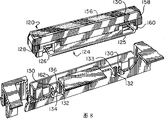
Fig. 3 is the decomposition diagram of the keyboard components of Fig. 1;
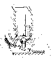
Fig. 4 is a perspective cutaway view, that is in the switch block of raised position of the keyboard components of Fig. 1;
Fig. 4 A is the partial cut away side views of the switch block of Fig. 4 when being in fully depressed position;
Fig. 4 B is used for the power of typical switch block of Fig. 4 and Fig. 4 A and the curve map of displacement relation curve;
Fig. 5 is the sectional side view of function key of the assembly of Fig. 1;
Fig. 6 is the plan view from above of the function key of Fig. 5;
Fig. 7 is the cross sectional side view of the function key of Fig. 5;
Fig. 8 is the decomposition diagram of space bar switch module of the keyboard components of Fig. 1; And
Fig. 9 is the cross sectional side view of the space bar switch module of Fig. 8.
Hereinafter with reference to accompanying drawing, particularly keyboard components 10 of the present invention is described referring to figs. 1 through Fig. 3 and Fig. 7.Keyboard components 10 expressions one keyboard, it can use with any common system such as computing machine, word processor, counter, data entry terminal, control panel or similar devices etc.In a preferred embodiment, keyboard components of the present invention is particularly suitable for using with medical ultrasonic system or some other medical or industrial system by microprocessor control, in this type systematic, because of working environment or user's the material the employed Signa Gel in the medical ultrasonic system that hand brought produces pollution problem.And keyboard components 10 of the present invention also is specially adapted to need operate in dark surrounds in the medical treatment and other application of this assembly.
Keyboard 10 comprises: shell 12; Key panel 14, but this finger-board face 14 has the button 16 of self-movement; A function key 17 and a space bar 18; Barrier film 20; Demarcation strip 22; Female PC plate 24 and sub-PC plate 26 in some applications.
A plurality of positions around panel 14 can be provided with one or more fasteners (snap) 30.Preferably: two fasteners 30 are set along panel 14 and space bar 18 adjacent forward edge; The edge that is positioned at right side shown in Figure 1 along panel 14 is provided with a fastener 30; Left side along as shown in Figure 1 panel 14 is provided with another fastener 30; And another fastener 30 is set along panel 14 and function key shown in Figure 1 17 adjacent top edge.But, also more or less fastener 30 can be set on demand.
Below will with reference to Fig. 7 typical fastener 30 be described especially.Each fastener 30 includes a flexible elasticity finger 29, and this finger only is connected with panel 14 in its proximal end and has a projection 27, and this projection is arranged near the far-end freely of above-mentioned finger.Projection 27 can engage with the convex shoulder 25 on being formed on shell 12 inside surfaces.The upper surface 23 that projection 27 has a lower surface that tilts 21 and tilts.Panel 14 be inserted shell 12, only needing downwards, pushing panel 14 gets final product.Lower surface 21 is pressed onto on the edge of shell 12 and makes finger 29 leave shell 12 to bias internal along the inside surface of shell 12 during to lower slider at finger 29.When finger 29 during near barrier film 20, because finger 29 can engage so protruding 27 surface 23 can be pushed with convex shoulder 25 because of returning elastically its original position.In a single day applied the power that enough makes progress during dismounting, upper surface 23 will be pressed onto on the convex shoulder 25, thereby makes projection 27 to bias internal.The bearing of trend of surface 23 general relative fingers 29 is 45, and the bearing of trend of surface 21 then general relative fingers 29 is 60 ° of angles.
Under panel 14, be provided with a translucent or transparent barrier film 20.Barrier film 20 is formed with a plurality of arches mound 32 in the mode of integral body and 33, one arch mounds 32 are associated with a button 16, and one encircles mound 33 and is associated with a button 17.One sealing gasket 34 that forms with integral way extends round the outer ledge of barrier film 20.When forming barrier film 20, be molded into arch mound 32 and 33 and sealing gasket 34 with this barrier film 20, therefore, the seam that on the surface of barrier film 20, does not exist liquid or gas to infiltrate.
Be provided with a dividing plate 22 under barrier film 20, this dividing plate is a nonconducting dividing plate, and it is separated female PC plate 24 with barrier film 20.Dividing plate 22 includes a plurality of openings 42,47 and 48.Each opening 42 all is associated with a button 16.Opening 42 makes to form between surface on the arch mound 32 of barrier film 20 and the electric contact area 78 on the PC plate 24 and electrically contacts.In addition, just as will be described, opening 42 can be used for the device that LED44 and so on is used for shining button.As shown in Figure 3, owing to following reason, the Width of opening 42 usually relative panels 14 is located with 45.Perforate 48 all is associated with each function key 17 with a plurality of openings 47.Opening 47 is used for LED45 and each button 17, and opening 48 then is associated with the LED46 of state index lamp.
Be provided with female PC plate 24 under dividing plate 22, this PC plate comprises necessary decoding of keyboard and electronic circuit.In addition, PC plate 24 also includes contact area 78, and in one embodiment, this contact area comprises by pushing button and 16 or 17 forms interdigitation pectination (interdigitating comb pattern) or the similar structures that is electrically connected.PC plate 24 also has and is respectively applied for the LED44 and 45 that illuminates button 16 and 17.LED44 and 45 is generally the LED (low profile LED) of low profile, and they provide the light of the low luminosity that is suitable for back-lighting.In general,, each button 16 is provided with two LED44, each button 17 then is provided with four LED45 for desirable illumination uniformity coefficient and intensity of illumination can be provided.Two LED44 align with each associated openings 42 on the dividing plate 22 so that make the light from LED44 pass the relevant arch mound 32 of dividing plate 22 arrival.But, should be realized that, as long as can obtain required uniformity coefficient and light intensity, also a single LED or other light source can be used for button 16 and 17.
In one embodiment, the below of female PC plate 24 is provided with a sub-PC plate 26.In general, sub-PC plate 26 has LED46, and these LED have constituted the light source of the status indicator lamp that is used for function key 17.Concerning state indication, need stronger illumination, therefore, need and compare bigger LED and different configurations with LED44.PC plate 26 uses bigger LED by providing required down suction to allow.But, should be appreciated that, if the LED that uses low profile so, just can be installed in LED46 female PC plate 24 and sub-PC plate 26 needn't be provided again to be provided for the desired light photograph of status indicator lamp.Each LED all with dividing plate 22 on an opening 48 and an opening 51 on the PC plate 24 be associated so that enter in the relevant arch mound 33 on the barrier film 20 from the light of LED46.
As previously mentioned, each arch mound 32 is associated with a source key 16, and each arch mound 33 then is associated with a rectangle function key 17.In general, it is circular that the section on arch mound 32 is generally, and arch mound 33 then is elongated so that hold the function key 17 of large-size.The size on described arch mound should be able to make this arch mound be generally power and the supporting uniformly that evenly makes progress for this key provides on the whole bottom of related key, thereby prevent that this button is crooked or not straight, thereby thisly crookedly or not straight finally can retrain the easy motion that button has hindered this button.
Below will with reference to Fig. 4 and Fig. 4 A typical button 16 and relevant arch mound 32 thereof be described especially.Each button 16 includes: a upper surface 48, and this upper surface has the zone of printing opacity; One opaque edge 50 and sidewall 52.Sidewall 52 can be transparent, also can be opaque, or translucent.The center of each button 16 all is a hollow.Vertical walls 54 is embossed in the key panel 14 and with each button 16 and is associated, and the center of this vertical walls includes the zone of a hollow.The bottom part 56 that is placed on the barrier film 20 is supporting wall 54.Be provided with sediment pan or liquid trap 58 between adjacent wall 54, this sediment pan or liquid trap are used to collect any liquid at edge 50 of slipping away.Before generation liquid flow to the danger of described barrier film downwards, the liquid heights in the sediment pan 58 always will rise to the upper end of wall 54 earlier more than 60.The structure of wall 54 can make the wall 52 of button 16 move so that guide the vertical moving of button 16 along it with closely-spaced relation.Space 62 between edge 50 and the wall 52 holds wall 54 in button 16 vertical moving processes.
Each button 16 includes a pair of relative finger 63, has projection 64 on the far-end of this finger.Finger 63 is formed on the wall 52 and only links in its proximal end and wall 52.The inside surface of wall 54 is provided with a pair of convex shoulder 66, each convex shoulder all align with relevant projection 64 and with this bump bonds, thereby limited button 16 along leave barrier film 20 upward to vertical moving, as shown in Figure 4.But convex shoulder 66 does not limit button 16 and moves towards barrier film 20 downwards.By finger 63 is curved inwardly to discharge projection 64 from convex shoulder 66, can pull down button 16.Similarly, wall 52 is glided so that finger 63 bendings are stuck in the position of convex shoulder 66 belows until projection 64 along wall 54, button 16 is resetted by downward pressing keys 16.In this way, just can pull down button 16, cleaning or replacing so that repair.
Light from LED44 can shine on the upper surface 48 through barrier film 20 and the hollow of button 16.If necessary, alphanumeric indicator (demonstration) can be arranged on the upper surface 48.In general, because the zone of upper surface 48 is printing opacities, so, can be opaque limiting this numeral or letter by making numeral or alphabetical peripheral region, thus an alphanumeric indicator formed.In this way, surperficial 48 the time when seeing through from the light of LED44, it is visible having only said numeral or letter, and the remainder of upper surface 48 then is lighttight.Usually coating is coated onto or is attached on the upper surface 48 to limit said alphanumeric indicator.But, should be appreciated that, also can use other known techniques that forms alphanumeric indicator, as be fixed on the surface 48 and the paper of numeral or letter or plastic foil etc. as described in delineating out.In addition, can also use lighttight alphanumeric indicator, during transparent region when see through upper surface 48 from the light of LED44 around, above-mentioned lighttight designator also can be visible.
Below will be especially with reference to Fig. 4 and Fig. 4 A explanation arch mound 32.Arch mound 32 generally comprises: a bottom flexible thin bar 68; One top flexible thin bar 71; One upper support ring 70; Bottom retainer and projection 74.Upper support ring 70 extends and is supporting the lower edge of the wall 52 of button 16 round the whole outer rim on wall 52 and arch mound 32.When pushing button 16 the time, the lower edge of wall 52 can be impartial with push down arch mound 32 symmetrically, therefore, arch mound 32 can be bent downwardly around its whole cross section or be out of shape equably.Comprise a conductive surface 76 such as the small pieces that carbon is housed on the distal lower end of projection 74, this surface is positioned at the side of barrier film 20 towards PC plate 24.Thereby when fully producing the switch effect that needs by lower convexity 74 to engage with aforementioned interdigitation finger, surface 76 can contact with the relevant range 78 on the PC plate 24.Retainer 72 makes this retainer 72 not be in position directly over the opening 48 to arrange perpendicular to the mode of the length direction of dividing plate 22 upper sheds 48 and to be positioned at usually.Therefore, when pressing arch mound 32, retainer 72 can engage with the surface engagement of dividing plate 22 rather than with LED44 or PC plate.The configuration on arch mound 32 can provide desirable " overtravel " by making this arch mound 32 meet predetermined power/displacement curve.Should be appreciated that, can regulate the size of thin slice 68 and thickness to meet any selected power/displacement curve.
In operating process, when pushing button 16 the time, lower foil 68 begins distortion, thereby sustained ring 70 and projection 74 are moved towards PC plate 24 downwards in uniform mode.Projection 74 can continue to move down until surface 76 runs into relevant zone 78.At this moment, the lasting downward power that acts on the button 16 can make thin slice 71 and thin slice 8 distortion, thereby makes sustained ring 70 continue to move towards PC plate 24 in a downward direction when projection 74 maintenances are static.The continuous deformation of thin slice 71 can make sustained ring 70 continue to move down the upper surface of running into dividing plate 22 until retainer 72.Retainer 72 can stop button 16 further to move down.In this way, run into zone 78 with after the operator provides desired tactile feedback, can produce the effect of " overtravel " on surface 76.
In case remove power down on the button 16, thin slice 68 and 71 intrinsic elasticity will make upper support ring 70 rise once again and be back to its original-shape until thin slice 71.After this, the intrinsic elasticity of lower foil 68 can make projection 74 rise and make sustained ring 70 and button 16 rises and returns its original-shape until lower foil 68.At this moment, button 16 has been back to its original projection state, as shown in Figure 4.Arch mound 32 can promote the projection 64 of fingers 63 against convex shoulder 66, thereby has guaranteed that button 16 can be back to the projection position identical with other button 16 on the keyboard.When projection 64 when being engaged in convex shoulder 66, arch mound 32 preferably can slightly be out of shape, and therefore, arch mound 32 can maintain the power that makes progress that acts on the button 16, thereby projection 64 is alignd with convex shoulder 66.
Fig. 4 B has illustrated the exemplary force/ displacement curve 154 and 156 on a schematic button 16 and relevant arch mound 32 thereof.But, should be appreciated that the curve shown in Fig. 4 B only is schematically, and the present invention is not limited to have the configuration of such certain force/displacement curve.In Fig. 4 B, ordinate represents with the gram to be the power of unit, and this power acts on surface 48 in a downward direction, and horizontal ordinate represents that then general relatively button 16 reference points are the perpendicular displacement of unit with the millimeter.162 places in the position, the power that adds is zero, thereby button 16 is in its normal projection position, this position is positioned at apart from the fixing preset distance place of reference point.When applying bigger downward power, because thin slice 68 distortion, thereby, from can increasing along curve 154 of described reference point to bottom offset.Point 164 places on curve 154, thin slice 68 " blocks " effectively, and perhaps sustained ring 70 surpasses certain a bit in the deformation process of thin slice 68, just can produce further displacement at this some place with less compelling force.In an exemplary embodiment, the maximum compelling force at this some place is about 75 ± 19 grams.Can produce the point 158 of further displacement on arrival curve 154.At point 158 places, the conductive surface 76 on the projection 74 can contact with the relevant range 78 on the PC plate 24.In one exemplary embodiment, put the compelling force at 158 places less than about 22 to 45 grams of the compelling force at point 164 places.After this, apply extra power and can make thin slice 68 and thin slice 71 distortion.Just as seen, thin slice 68 and the required power of 71 distortion are greater than and only make the required power of thin slice 68 distortion.Point 160 places on curve 154, retainer 72 engages with dividing plate 22, thereby applies extra power and produce very little or do not produce extra displacement.In a typical embodiment, put the power that 160 places add and be about 130 grams.In one embodiment, total distance that button 16 is advanced to point 160 places from the point 162 on the curve 154 is about 3.1 millimeters, and total distance of advancing to point 158 places from the point 162 on the curve 154 is about 1.85 millimeters.
In case button 16 has arrived the point 160 on the curve 154, the reducing of compelling force can make this key be back to its projection state along curve 156.When power reduced, this key can be back to the point 159 on the curve 156, and at this moment, thin slice 71 had turned back to its normal condition already, as shown in Figure 4.After this, when " blocked " on arch mound 32, sustained ring 70 can rise, and thin slice 68 can continue to return its normal shape as shown in Figure 4 between point 159 on the curve and point 162.In an exemplary embodiment, the minimum recuperability at point 159 places on the curve 156 is about 25 grams.Just as seen, because the hysteresis phenomenon in 32 distortion of arch mound, thereby power/displacement curve 154 is different from power/displacement curve 156.
Below will with reference to Fig. 5 to Fig. 7 typical functions key 17 be described especially.Because function key 17 has a status indicator lamp 82 and rectangular on cross sectional shape, rather than resemble and on cross sectional shape, be square the button 16, so function key 17 is different from button 16.As a result, each arch mound 33 all is same elongated so that support the whole lower surface of related key 17 equably.In general, although optional, can be embossed in shell 84 in the panel 14 and have at least some button 17 to be surrounded by a shell 84.
Each button 17 includes: the upper surface 86 of a printing opacity; One lighttight edge 88 and the sidewall 90 that extends downwards.Sidewall 90 can be opaque, also can be transparent, or translucent.Be pressed with upwardly extending wall 92 at panel 14 internal molds, this wall has impaled the space of an opening.Concerning each button, all there are two relative flexible elasticity fingers 91 to be formed on the sidewall 90, each finger 91 all has the projection 96 that is formed on the far-end.Each finger 91 only links to each other with wall 90 in the proximal end.Wall 92 includes a pair of relative convex shoulder 94, and each convex shoulder all aligns with relevant projection 96 and is suitable for and this bump bonds.The same with button 16, wall 92 formed have sectional dimension and the shape substantially the same with sidewall 90, therefore, sidewall 90 can be advanced and guided by this wall along wall 92.Space 89 between wall 90 and the edge 88 can hold wall 92.Projection 96 has limited button 17 with relevant convex shoulder 94 and has left moving up of barrier film 20, and the constant distortion of encircleing mound 33 can make protruding 96 to contact with convex shoulder 94.The same with button 16, by inwardly pushing finger 91, just can pull down button 17 so that projection 96 is discharged from convex shoulder 94.Similarly, as long as pressing keys 17 is stuck in the lower position of convex shoulder 94 so that finger 91 curves inwardly when wall 92 moves in projection until projection 96, button 17 is resetted.One sediment pan is being set with slip away any liquid at button 17 edges 88 of collection between the adjacent wall 92 or between the wall of wall 92 and associated enclosure 84.
Except that arch mound 33 is elongated so that agreeing with the elongated shape of button 17, arch mound 33 is similar to arch mound 32 basically.Arch mound 33 comprises: a bottom thin slice 100; One upper foil 102; Sustained ring 104; Two retainers 106; Two projectioies 108 and a conductive surface 110, this surface is arranged on the lower end of each projection 108.As previously mentioned, each conductive surface 110 all is positioned at barrier film 20 towards a side of PC plate 24 and be used for contacting to realize switching function with relevant zone 112.In general, although optional, four LED45 can be set to shine each button 17.Each LED45 all has the associated openings 47 that is positioned on the dividing plate 22, and LED45 generally is arranged in the rectangular configuration that the rectangular shape with button 17 aligns.Projection 108 is passed the opening between LED45 107 on the dividing plate 22.The upper surface of retainer 106 contact dividing plates 22 between LED45.Preferably the long limit with retainer 106 relative button 17 formed rectangles medially is arranged on the arch mound 33, and the square limit of projection 108 relative button 17 formed rectangles medially is arranged on the arch mound 33.
In operating process, when pushing button 17 the time, thin slice 100 can distortion and projection 108 move until surface 110 towards PC plate 24 downwards and contact with relevant zone 112.Further downward power can make thin slice 102 distortion and continue to make sustained ring 104 to move down until retainer 106 and contact with the upper surface of dividing plate 22 and limit downward mobile.Cancelling downward power can make thin slice 102 and thin slice 100 contact convex shoulder 94 to button 17 is resetted until projection 96 upward along what leave PC plate 24.Light from LED45 is upwards advanced with the upper surface 86 of irradiation button 17 along the hollow of button 17.Can be on upper surface 86 use an alphanumeric indicator 79 in the mode identical with button 16.
Function key 17 also comprises a status indicator lamp mark 82.In general, illuminate mark 82 and connect, perhaps do not illuminate mark 82 with the indication off-state with indicator cock.Because status indicator lamp mark 82 is arranged on the described function key, rather than is arranged on the next door of this key, so the present invention is different from the system of some prior art.Button 17 comprises a photoconductive tube 118, and this photoconductive tube extends to the lower edge of wall 90 downwards always towards barrier film 20 from mark 82.The lower end 109 of photoconductive tube 118 contacts with the sustained ring 104 on arch mound 33 or is close to this sustained ring 104.In general, photoconductive tube 118 is molded into the hollow part of button 17 and is made of solid plastic material transparent, conducting light.One the high light intensity light source of narrow angle such as LED46 aligns with the lower end 109 of photoconductive tube 118.In general, the size and shape of LED can make it be installed on the PC plate 26 so that required gap to be provided.LED passes the respective openings on the PC plate 24.But,, so, just it can be installed on female PC plate 24 if LED is enough flat and desirable high strength light can be provided.LED46 and zone 112 form to be electrically connected with the relevant on off state situation of reflection and button 17.Thereby opening 48 and the arch mound 33 passed on the dividing plate 22 from the light of LED46 are received by the lower end 109 of photoconductive tube 118.Photoconductive tube 118 will be passed to the mark 82 that is arranged on the upper surface 86 from the light of LED46 along its length direction.Best, although not necessarily,, can watch easily mark 82 from the top and the sidepiece of button 17 thereby comprising luxuriant and rich with fragrance the Huangshui River ear lens.
Below will illustrate that with reference to Fig. 8 and Fig. 9 another aspect of the present invention is space bar 120 and relevant arch mound 122 especially.Space bar 120 comprises: the upper surface 156 of printing opacity; Opaque edge 158 and wall 160, this wall can be transparent, also can be translucent, or opaque.Panel 14 internal molds are pressed with vertical wall 162, and wall 160 can move along wall 162, and the motion of wall 162 guiding walls 160.The same with button 17, each end of space bar 120 is provided with a flexible finger 164, this finger comprises a projection, and this projection and relevant convex shoulder 159 in being embossed in wall 162 contact to limit moving upward and can pulling down space bar 120 when finger 164 deflections of space bar 120.
The structure on arch mound 122 and the structural similarity on arch mound 33.Arch mound 122 comprises lower foil 140, upper foil 142, two projectioies 144, sustained ring 146 and two retainers 148. Conductive surface 150 and 152 contacts of relevant zone are so that form required switching function, and said conductive surface generally includes the small pieces that carbon is housed.Two LED can be arranged on the PC plate 24 of arch 122 belows, mound, so that illuminate space bar 120.Other LED is set along the length direction of space bar 120.
Preferably does not extend along the whole length of space bar 120 on arch mound 122.Owing to can not press next end with amount identical and identical speed, so this arch mound more is difficult to make and itself is exactly unsettled with the other end.For provide space bar 120 required stability and the arch mound that can use limited length, be provided with a stabilizer bar 124.Stabilizer bar 124 can stop space bar 120 swing or stop space bar 120 around rotating with the perpendicular axis of its length direction.Stabilizer bar 124 comprises a connecting rod 125, and this connecting rod is elongated on the length direction of space bar 120.Stabilizer bar 124 also comprises: cross member 126, and these parts extend in mode common and that connecting rod 125 length directions are perpendicular; And installation end 128, this installation end is controlled the direction that is parallel to connecting rod 125 bearing of trends usually and is extended from parts 126.Thereby parts 126 pass the slit 130 that is formed on the space bar 120 and have enough elasticity can temporarily be out of shape during insertion so that installation end 128 passes through slit 130.After the insertion, parts 126 intrinsic elasticity installation end 128 can be released outside the end of slits 130, thereby prevent from installation end 128 is pulled out slit 130.
In operating process, when space bar 120 rose or descend, it was static basically that connecting rod 125 removes around extending along connecting rod 125 and being parallel to the axis rotation of this length of connecting rod.Parts 126 long enoughs thereby can slide into and skid off rising and the decline of slit 130 to hold space bar 120, still, 128 of installation ends can stop parts 126 to break away from slit 130 fully.Slit 130 is enough wide thereby can hold the rotation of connecting rod 125.But space bar 120 can not be around the axis swing perpendicular to its length direction, and this is because avoided this motion thereby slit 130 and 136 has clamped stabilizer bar 124.Space bar 120 any locational any downward power all will make whole space bar descend equably along its length.
Foregoing invention provides a kind of keyboard components, and this keyboard components has back light and comprises that one is used for the overtravel structure of each button, and, in this keyboard components, be not subjected to the influence of keyboard with a liquid-tight seal protection electronic circuit.In addition, some function key is provided with status indicator lamp, simultaneously, whole keyboard can be comprised that each button temporarily takes apart so that cleaning and disinfection.At last, a stabilizer bar makes the present invention to use with an elongated space bar.Although can use other suitable material,, most assemblies can be pressed into plastic pattern.In general, barrier film 20 is to be about 50 silicon rubber of losing Lip river (durometer) and to constitute by having.
By above explanation, the expert of present technique may expect belonging to modification or the improved form in the scope of the invention.Above explanation only is that schematically following claim and their equivalent define scope of the present invention.
Claims (9)
1. a keyboard (10) comprising:
One has the panel (14) of a plurality of buttons (16,17), and said button (16,17) has a upper surface (48,46), and the zone of a printing opacity is arranged on this upper surface;
One has the circuit board (24) of circuit, and this circuit board comprises contact area (78,112);
One translucent barrier film (20), this barrier film is arranged between described panel (14) and the described circuit board (24) and between described panel (14) and described circuit board (24) and has formed liquid-tight sealing, described barrier film (20) comprises a main body and a plurality of flexible elasticity arch mound (32,33) that becomes integral body with this described main body, and each arch mound (32,33) all is associated with a described button (16,17);
Be arranged on the light source (44,46) on the described circuit board (24), can pass the described upper surface (48,86) of described barrier film and described button (16,17) from the light of described light source; And
One conductive surface (76,110,150), this surface is associated with each described arch mound (32,33) and is arranged on described barrier film (20) on a side of described circuit board (24), press that button (16,17) on the described keyboard can make relevant arch mound (32,33) thus distortion is ordered about the described conductive surface (76,110) on described relevant arch mound (32,33) and is contacted with the last relevant described zone of described circuit board (24) (78,122).
2. keyboard according to claim 1 is characterized in that, each described button (16,17) all comprises the inside of a hollow so that pass the described upper surface of described button (16,17) from the light of described light source.
3. keyboard according to claim 1 is characterized in that, it also comprises:
One status indicator lamp mark (82), this mark are arranged on the described upper surface (86) of at least one described button (17);
One photoconductive tube (118), this photoconductive tube have a lower end and extend to status indicator lamp mark (82) on the described upper surface (86) of this described button (17) from the relevant arch mound (33) of a described button (17); And
One special light source (46), this light source are set in place on the circuit board (24) under the described lower end of described photoconductive tube (118), and described special light source (46) is according to the state of a described button (17) and luminous selectively.
4. keyboard according to claim 1 is characterized in that, said light source comprise two with the relevant light emitting diode of each described button (16).
5. keyboard according to claim 1 is characterized in that, said arch mound (32,33) comprising:
Parts that are used for supporting a relevant button of described button (16,17);
One first thin slice (68,100), this thin slice make described parts (70,104) be connected with the main body of described barrier film (20);
A projection (74,108) of extending towards described plate (22,24,26) downwards, said projection (27,64,74,96,108,144) in its lower end and barrier film (20) have a conductive surface (76,110) towards a side of circuit board (24); And
One second thin slice (71,102), this thin slice makes described parts (70,104) with described projection (74,108) be connected, by next relevant button (16,17) can make first thin slice (68,100) be out of shape and make described projection (74,108) the relevant contact area (78 on circuit board (24), 112) move, at described conductive surface (76,110) touch described relevant contact area (78,112) afterwards, further press described relevant button (16,17) can make described second thin slice (71,102) be out of shape and make described parts (70,104) move towards described circuit board (24).
6. keyboard according to claim 1, it is characterized in that, it also comprises each described button (16 of encirclement, 17) guiding wall (52,90), and, each described button (16,17) include the flexible finger (63 of a pair of relative spacing, 91), this finger and described guiding wall (52,90) convex shoulder (66 on, 94) have a projection (64 on the contacted far-end, 96), thus limited described button (16,17) move upward and by finger (63,91) distortion and pull down each described button (16 from described panel (14), 17).
7. keyboard according to claim 1 is characterized in that, it also comprises:
One shell (12), described circuit board (24) and described barrier film (20) all are fixed on this shell; And
A plurality of flexible elasticity fingers (29), these fingers are arranged on the described panel (14), each finger (29) all has a projection (27), this projection removably with described shell (12) on relevant convex shoulder (25) engage, thereby described panel (14) and described shell (12) are coupled together and can pull down described panel (14) by the distortion of described finger (29), described panel (14) can be independent of described barrier film (20) and described circuit board (24) carries out dismounting.
8. keyboard according to claim 1 is characterized in that, it also comprises:
A space bar (120), this key has certain length and bearing of trend;
An arch mound (122), this arch mound is associated with the whole formation of described barrier film (20) and with described space bar (120), described arch mound (122) prolongs on the described bearing of trend of described space bar (120), and the development length on described arch mound (122) is less than the development length of described space bar (120);
A stabilizer bar (124), described stabilizer bar (124) has the two ends that put in slit (130), and said slit then is formed on the described space bar (120); And
A grab (130,132), this grab is arranged on panel (14) and goes up so that clamp described stabilizer bar (124), and said grab (130,132) can stop described stabilizer bar (124) and described space bar (120) around the axial-movement perpendicular to described bearing of trend.
9. as the keyboard as described in the claim 7, it is characterized in that, described barrier film (20) comprises a sealing gasket (34) around this barrier film outer rim extension, and this sealing gasket is engaged in the corresponding forming pockets (36) in the mode of sealing, and this groove then extends around the outer rim of described shell (12).
Applications Claiming Priority (2)
| Application Number | Priority Date | Filing Date | Title |
|---|---|---|---|
| US25347594A | 1994-06-03 | 1994-06-03 | |
| US253,475 | 1994-06-03 |
Publications (1)
| Publication Number | Publication Date |
|---|---|
| CN1116331A true CN1116331A (en) | 1996-02-07 |
Family
ID=22960430
Family Applications (1)
| Application Number | Title | Priority Date | Filing Date |
|---|---|---|---|
| CN95106643A Pending CN1116331A (en) | 1994-06-03 | 1995-05-31 | Full travel, sealed, fully backlighted keyboard |
Country Status (5)
| Country | Link |
|---|---|
| US (1) | US5612692A (en) |
| EP (1) | EP0685860A1 (en) |
| JP (1) | JPH07334283A (en) |
| KR (1) | KR960001946A (en) |
| CN (1) | CN1116331A (en) |
Cited By (10)
| Publication number | Priority date | Publication date | Assignee | Title |
|---|---|---|---|---|
| CN1302365C (en) * | 2004-04-01 | 2007-02-28 | 华硕电脑股份有限公司 | Electronic device with touch-control type push-button |
| CN1328641C (en) * | 2004-02-16 | 2007-07-25 | 华硕电脑股份有限公司 | Electronic device with transparent panel |
| WO2010135865A1 (en) * | 2009-05-27 | 2010-12-02 | Zhong Renkang | Illuminated soft keyboard and electrical device |
| CN1996499B (en) * | 2006-12-18 | 2011-01-05 | 徐州市精英电器技术有限公司 | Double-side water-proof embedded plastic instrument panel |
| CN102252275A (en) * | 2011-05-24 | 2011-11-23 | 上海向隆电子科技有限公司 | Backlight module and keyboard thereof |
| CN102737888A (en) * | 2011-04-06 | 2012-10-17 | Abb股份有限公司 | Rocker holder with at least one actuation rocker of a door station or residence station of a building communication system |
| CN102737889A (en) * | 2011-04-06 | 2012-10-17 | Abb股份有限公司 | Rocker holder with at least one actuation rocker of a door station or residence station of a building communication system |
| CN105848431A (en) * | 2015-01-30 | 2016-08-10 | 卡西欧计算机株式会社 | Electronic device |
| CN107678559A (en) * | 2017-11-22 | 2018-02-09 | 苏州达方电子有限公司 | A kind of key board unit |
| CN110379660A (en) * | 2018-04-12 | 2019-10-25 | 普瑞有限公司 | For operating the switching device of motor vehicle component |
Families Citing this family (91)
| Publication number | Priority date | Publication date | Assignee | Title |
|---|---|---|---|---|
| US5867149A (en) * | 1995-08-14 | 1999-02-02 | Intertactile Technologies Corporation | Switch key image display and operator/circuit interface |
| US5801345A (en) * | 1996-06-21 | 1998-09-01 | Acuson Corporation | Keyboard assembly incorporating multiple lighting modes for improved user feedback |
| DE19626626C2 (en) * | 1996-07-02 | 2000-08-03 | Cherry Mikroschalter Gmbh | Splashproof keyboard |
| DE29702729U1 (en) * | 1997-02-07 | 1997-04-03 | Schroeter Rosemarie | Adjustable communication keyboard lighting |
| US5933133A (en) * | 1997-02-18 | 1999-08-03 | Lohr; Daniel James | Low-impact keyboard |
| US7133726B1 (en) * | 1997-03-28 | 2006-11-07 | Applera Corporation | Thermal cycler for PCR |
| KR100252116B1 (en) * | 1997-12-29 | 2000-04-15 | 윤종용 | Keyboard |
| TW371501U (en) * | 1998-07-07 | 1999-10-01 | Acer Comm & Multimedia Inc | Keyboard structure |
| TW385891U (en) | 1998-07-07 | 2000-03-21 | Acer Peripherals Inc | Water-proof keyboard |
| US7335843B2 (en) * | 1998-11-13 | 2008-02-26 | Firefly International, Inc. | Computer keyboard backlighting |
| US6322229B1 (en) | 1998-11-13 | 2001-11-27 | Questech International, Inc. | Backlighting for computer keyboard |
| US6765503B1 (en) * | 1998-11-13 | 2004-07-20 | Lightpath Technologies, Inc. | Backlighting for computer keyboard |
| US20080212307A1 (en) * | 1998-11-13 | 2008-09-04 | Chan Sam E J | Computer keyboard backlighting |
| US20090091478A1 (en) * | 1998-11-13 | 2009-04-09 | Chan Sam E J | Computer keyboard backlighting |
| US6871978B2 (en) | 1998-11-13 | 2005-03-29 | Lightpath Technologies, Inc. | Computer keyboard backlighting |
| US6191939B1 (en) | 1998-12-23 | 2001-02-20 | Gateway, Inc. | Keyboard illumination via reflection of LCD light |
| US6590508B1 (en) | 1999-05-24 | 2003-07-08 | Bryan F. Howell | Backlit keyboard |
| US20080143560A1 (en) * | 1999-09-15 | 2008-06-19 | Michael Shipman | Lightpipe for illuminating keys of a keyboard |
| US20090201179A1 (en) | 1999-09-15 | 2009-08-13 | Michael Shipman | Illuminated keyboard |
| US10013075B2 (en) | 1999-09-15 | 2018-07-03 | Michael Shipman | Illuminated keyboard |
| US6497521B1 (en) | 1999-12-17 | 2002-12-24 | Daniel James Lohr | No-impact keyboard |
| US6365848B1 (en) | 2000-02-25 | 2002-04-02 | Hewlett-Packard Company | Key panel and strip switch assembly configurations having variable aspect ratios and method of making |
| US20070063978A1 (en) * | 2000-04-06 | 2007-03-22 | Cathey David A | Cordless computer keyboard with illuminated keys |
| US7184024B2 (en) * | 2000-06-30 | 2007-02-27 | Nokia Corporation | Method and apparatus for mapping an input location with a displayed functional representation |
| DE20013019U1 (en) | 2000-07-27 | 2001-12-20 | Liebherr Hausgeraete | Electronics control unit |
| US6542355B1 (en) * | 2000-09-29 | 2003-04-01 | Silitek Corporation | Waterproof keyboard |
| WO2002093603A1 (en) * | 2001-05-14 | 2002-11-21 | John James Doyle | A keyboard for a computer |
| US6797902B2 (en) | 2001-06-27 | 2004-09-28 | Sotai Ltd. | Illuminable computer keyboard |
| US20030006128A1 (en) * | 2001-07-03 | 2003-01-09 | Giles John T. | Two-shot molded backlit switch cap and method of manufacture |
| US20030098854A1 (en) * | 2001-11-28 | 2003-05-29 | Laliberte Edward Robert | Integrated touchscreen and keys in same matrix |
| TW510561U (en) | 2001-12-11 | 2002-11-11 | Silitek Corp | Push button structure |
| US6743993B1 (en) | 2002-02-21 | 2004-06-01 | Advanced Input Devices, Inc. | Backlit full travel key assembly |
| US7009121B2 (en) | 2002-04-25 | 2006-03-07 | Preh-Werke Gmbh & Co. Kg | Keyboard, especially for electronic payment terminals, and keypad |
| DE10218442B3 (en) * | 2002-04-25 | 2004-01-29 | Preh-Werke Gmbh & Co. Kg | Keyboard, especially for cash registers |
| US20040075647A1 (en) * | 2002-10-17 | 2004-04-22 | Bean James J. | Keyboard reconfiguration method and device |
| FR2846144B1 (en) * | 2002-10-18 | 2005-04-15 | Thales Sa | KEYBOARD WATERPROOF |
| US6765158B1 (en) | 2003-05-08 | 2004-07-20 | Lear Corporation | Low profile switch with flat wire harness |
| US6737596B1 (en) | 2003-05-08 | 2004-05-18 | Lear Corporation | Integrated switch bank |
| US20040226248A1 (en) * | 2003-05-16 | 2004-11-18 | Wu Lee Hong | Type of splash-resistant modular keyboard for computers |
| US6861600B1 (en) * | 2003-10-01 | 2005-03-01 | Lumitex, Inc. | Integrated switch and backlight assembly |
| US7084360B2 (en) * | 2004-07-28 | 2006-08-01 | Lear Corporation | Elastomeric vehicle control switch |
| DE102004045697B3 (en) * | 2004-09-21 | 2006-05-24 | Fujitsu Siemens Computers Gmbh | keyboard |
| US20060250351A1 (en) * | 2004-09-21 | 2006-11-09 | Fu Peng C | Gamepad controller mapping |
| NL1027160C2 (en) * | 2004-10-01 | 2006-04-04 | Suzo Internat Nl B V | Press button assembly comprises operating part fixed to operating panel and switch part in apparatus at distance from panel |
| US20060132449A1 (en) * | 2004-12-21 | 2006-06-22 | International Business Machines Corporation | System, apparatus, and method for displaying variable legends on key buttons |
| US11216078B2 (en) | 2005-01-18 | 2022-01-04 | Michael Shipman | Illuminated keyboard |
| DE102005026894B4 (en) * | 2005-06-10 | 2007-10-18 | Fujitsu Siemens Computers Gmbh | Key arrangement for an elongated key and use of a key arrangement |
| JP4597041B2 (en) * | 2005-11-21 | 2010-12-15 | 株式会社リコー | Operation panel and image forming apparatus |
| US20070235370A1 (en) * | 2006-03-31 | 2007-10-11 | Anthony Reale | Protective chassis cover system and method |
| US20080036003A1 (en) * | 2006-08-09 | 2008-02-14 | Goda Technology Co., Ltd. | Backlighted membrane switch |
| DE102006047590A1 (en) * | 2006-10-05 | 2008-04-10 | Robert Bosch Gmbh | Cleaning-friendly button device |
| TWM313926U (en) * | 2006-12-27 | 2007-06-11 | Cal Comp Electronics & Comm Co | Bluetooth headset structure with sliding function |
| US7504596B2 (en) * | 2007-06-18 | 2009-03-17 | Zippy Technology Corp. | Keyboard |
| US7741979B2 (en) * | 2007-07-06 | 2010-06-22 | Pacinian Corporation | Haptic keyboard systems and methods |
| US8199033B2 (en) | 2007-07-06 | 2012-06-12 | Pacinian Corporation | Haptic keyboard systems and methods |
| US8248277B2 (en) * | 2007-07-06 | 2012-08-21 | Pacinian Corporation | Haptic keyboard systems and methods |
| US20090262492A1 (en) * | 2007-10-26 | 2009-10-22 | Seal Shield, Llc | Submersible keyboard |
| US7671290B2 (en) | 2007-10-29 | 2010-03-02 | Research In Motion Limited | Illuminated key-pad assembly |
| US8132976B2 (en) * | 2007-12-05 | 2012-03-13 | Microsoft Corporation | Reduced impact keyboard with cushioned keys |
| US8046032B2 (en) * | 2008-01-16 | 2011-10-25 | Hewlett-Packard Development Company, L.P. | Panel construction for housing keypads of mobile computing device |
| US8310444B2 (en) * | 2008-01-29 | 2012-11-13 | Pacinian Corporation | Projected field haptic actuation |
| US7983036B2 (en) * | 2008-01-30 | 2011-07-19 | Hewlett-Packard Development Company, L.P. | Flexible sheet with sealing skirt for keyboard assembly |
| DE102008015111B3 (en) * | 2008-01-31 | 2009-06-10 | Preh Gmbh | Fluid protected control element for use in motor vehicle, has guide and groove walls extending in direction of rotary knob and pushbutton, and downpipe guiding fluid striking on guide plate onto printed circuit board's oppositely lying side |
| US8294600B2 (en) * | 2008-02-15 | 2012-10-23 | Cody George Peterson | Keyboard adaptive haptic response |
| US8203531B2 (en) | 2008-03-14 | 2012-06-19 | Pacinian Corporation | Vector-specific haptic feedback |
| US8050019B2 (en) * | 2008-03-18 | 2011-11-01 | Research In Motion Limited | Keypad with water and dust protection |
| TW201005780A (en) * | 2008-07-30 | 2010-02-01 | Chicony Electronic Co Ltd | Key structure |
| WO2010032151A1 (en) * | 2008-09-19 | 2010-03-25 | Koninklijke Philips Electronics, N.V. | Control panel overlay for diagnostic ultrasound equipment |
| US9563281B2 (en) * | 2008-11-11 | 2017-02-07 | Hewlett-Packard Development Company, L.P. | Keyboard illumination apparatus and method |
| US8500348B2 (en) * | 2008-11-24 | 2013-08-06 | Logitech Europe S.A. | Keyboard with ultra-durable keys |
| FR2939215A1 (en) * | 2008-11-28 | 2010-06-04 | Thales Sa | RETROECLATIVE WATERPROOF KEYBOARD |
| CN201498397U (en) * | 2009-07-31 | 2010-06-02 | 深圳富泰宏精密工业有限公司 | Key component |
| US20110074739A1 (en) * | 2009-09-30 | 2011-03-31 | Microsoft Corporation | Light-transmissive key and optically-recognizable signature |
| US8283582B2 (en) * | 2010-06-30 | 2012-10-09 | Research In Motion Limited | Deflection web for a keypad assembly |
| US9007307B2 (en) | 2010-08-09 | 2015-04-14 | Apple Inc. | Method and apparatus for enhancing keycap legend visibility in low light conditions |
| US9189078B2 (en) | 2010-12-20 | 2015-11-17 | Apple Inc. | Enhancing keycap legend visibility with optical components |
| US8206047B1 (en) | 2011-06-24 | 2012-06-26 | TouchFire, Inc. | Keyboard overlay for optimal touch typing on a proximity-based touch screen |
| KR20130039457A (en) * | 2011-10-12 | 2013-04-22 | 삼성전자주식회사 | Control panel assembly and washing machine having the same |
| CN103455152B (en) * | 2013-09-09 | 2016-07-13 | 江苏和乔科技股份有限公司 | A kind of connecting structure of keyboard digital keypad |
| US9317202B2 (en) | 2013-09-12 | 2016-04-19 | TouchFire, Inc. | Keyboard overlay that improves touch typing on small touch screen devices |
| US20150235543A1 (en) * | 2014-02-19 | 2015-08-20 | Alcatel-Lucent Usa Inc. | Network Switch With Enhanced Interface |
| CN104021968A (en) * | 2014-06-20 | 2014-09-03 | 上海宏英智能科技有限公司 | Vehicle-mounted CAN bus key panel and control method thereof |
| DE102014019248B4 (en) * | 2014-12-19 | 2017-05-11 | Audi Ag | Operating device for a vehicle, in particular a passenger car |
| CN105353885A (en) * | 2015-10-30 | 2016-02-24 | 昆山洺九机电有限公司 | Multi-functional waterproof keyboard |
| CA2962836C (en) | 2016-04-06 | 2023-07-04 | Dynagen Technologies Incorporated | Keypad with replaceable key labels |
| TWI571771B (en) * | 2016-07-11 | 2017-02-21 | 致伸科技股份有限公司 | Optical keyboard |
| CN107610965A (en) * | 2016-07-12 | 2018-01-19 | 致伸科技股份有限公司 | Optical profile type keyboard |
| WO2018112841A1 (en) * | 2016-12-22 | 2018-06-28 | 海能达通信股份有限公司 | Terminal and snap dome assembly thereof |
| US10394342B2 (en) * | 2017-09-27 | 2019-08-27 | Facebook Technologies, Llc | Apparatuses, systems, and methods for representing user interactions with real-world input devices in a virtual space |
| WO2019156672A1 (en) * | 2018-02-08 | 2019-08-15 | Hewlett-Packard Development Company, L.P. | Keyboard keys |
| EP4022659A1 (en) * | 2019-08-28 | 2022-07-06 | IDD Aerospace Corporation | Low profile switch panel assembly |
Family Cites Families (42)
| Publication number | Priority date | Publication date | Assignee | Title |
|---|---|---|---|---|
| US4314112A (en) * | 1971-08-23 | 1982-02-02 | Hewlett-Packard Company | Keyboard having switches with tactile feedback |
| US4000389A (en) * | 1971-08-23 | 1976-12-28 | Hewlett-Packard Company | Printed circuit board and contact assembly for keyboard switch assemblies |
| US3941953A (en) * | 1971-08-23 | 1976-03-02 | Hewlett-Packard Company | Keyboard having switches with tactile feedback |
| US3898421A (en) * | 1972-08-18 | 1975-08-05 | Matsushita Electric Ind Co Ltd | Push button switch with elastic conductive sheet |
| US3890480A (en) * | 1974-05-23 | 1975-06-17 | Cincinnati Milacron Inc | Hermetic sealing structure for electronic keyboard apparatus |
| US4021630A (en) * | 1975-04-25 | 1977-05-03 | Neomed Incorporated | Hermetically sealed resilient contact switch having surgical applications |
| US4081898A (en) * | 1976-04-19 | 1978-04-04 | Texas Instruments Incorporated | Method of manufacturing an electronic calculator utilizing a flexible carrier |
| US4056701A (en) * | 1976-07-08 | 1977-11-01 | Bowmar Instrument Corporation | Low profile lighted push button switch |
| US4292516A (en) * | 1979-09-14 | 1981-09-29 | Burroughs Corporation | Photo-optical keyboard having debris protection |
| CH651153A5 (en) * | 1980-02-07 | 1985-08-30 | Orbisphere Corp | KEYPAD AND ITS USE. |
| US4367380A (en) * | 1980-08-27 | 1983-01-04 | Oak Industries Inc. | Keyboard assembly and components therefor |
| US4352968A (en) * | 1981-02-09 | 1982-10-05 | Kb Denver, Inc. | Elastomeric boot for a keyboard subassembly |
| FR2511941B1 (en) * | 1981-09-01 | 1988-02-05 | Telemecanique Electrique | MODULAR, WATERPROOF, TOUCHPAD KEYBOARD |
| US4430531A (en) * | 1982-03-15 | 1984-02-07 | Hewlett-Packard Company | Snap disc keyboard |
| US4491692A (en) * | 1982-11-05 | 1985-01-01 | Lee Shan S | Light-emitting device mounted under keybuttons of a keyboard |
| JPS5987720A (en) * | 1982-11-11 | 1984-05-21 | シャープ株式会社 | Pushbutton switch |
| US4677268A (en) * | 1983-03-28 | 1987-06-30 | The Gates Corporation | Elastomeric switch control device |
| DE3481670D1 (en) * | 1983-04-20 | 1990-04-19 | Bebie & Co | KEYBOARD ARRANGEMENT. |
| US4644326A (en) * | 1983-06-03 | 1987-02-17 | Secure Keyboards Limited | Unitary key panel |
| US4500758A (en) * | 1983-07-05 | 1985-02-19 | Hewlett-Packard Company | Keyboard switch assembly having sensory feedback |
| US4489227A (en) * | 1984-01-11 | 1984-12-18 | Sheldahl, Inc. | Back lighted, full travel push button membrane keyboard |
| GB8402974D0 (en) * | 1984-02-03 | 1984-03-07 | Npm Int | Switches and keyboards |
| US4758701A (en) * | 1984-03-14 | 1988-07-19 | Allen-Bradley Company | Indicator light assembly for control panel |
| FR2602609B1 (en) * | 1986-08-07 | 1988-11-10 | Alsthom Cgee | ELECTRIC KEYBOARD WITH PUSH BUTTONS |
| US4796007A (en) * | 1987-01-05 | 1989-01-03 | Ncr Corporation | Micro-motion keyboard |
| US4772769A (en) * | 1987-02-06 | 1988-09-20 | Burr-Brown Corporation | Apparatus for selective backlighting of keys of a keyboard |
| US4806908A (en) * | 1987-05-14 | 1989-02-21 | Astronics Corporation | Low profile backlighted keyboard |
| US4809126A (en) * | 1987-08-05 | 1989-02-28 | Hewlett-Packard Company | Electrostatic discharge proof keypad |
| DE3809770A1 (en) * | 1988-03-23 | 1989-10-05 | Preh Elektro Feinmechanik | KEY SWITCH |
| JPH01174820U (en) * | 1988-05-30 | 1989-12-12 | ||
| US4918445A (en) * | 1988-07-20 | 1990-04-17 | Hewlett-Packard Company | Scanning, row-column type keyboard |
| JPH0629860Y2 (en) * | 1988-07-21 | 1994-08-10 | 株式会社東芝 | Key switch structure |
| US4913387A (en) * | 1989-03-17 | 1990-04-03 | Hewlett-Packard Company | Apparatus for removably mounting a computer input device |
| US5015829A (en) * | 1989-04-28 | 1991-05-14 | Hewlett-Packard Company | Key pad and front panel assembly for an electronic instrument |
| US5089690A (en) * | 1990-12-14 | 1992-02-18 | Hewlett-Packard Company | Keyboard overlay |
| DE9102919U1 (en) * | 1991-03-12 | 1991-06-06 | Aeg Mobile Communication Gmbh, 7900 Ulm, De | |
| US5138119A (en) * | 1991-03-15 | 1992-08-11 | Lucas Duralith Corporation | Backlit tactile keyboard with improved tactile and electrical characteristics |
| US5149923A (en) * | 1991-03-15 | 1992-09-22 | Lucas Duralith Corporation | Backlit tactile keyboard with improved tactile and electrical characteristics |
| US5228561A (en) * | 1991-04-01 | 1993-07-20 | Hewlett-Packard Company | Long traveling button switch with enhanced user feedback |
| US5172805A (en) * | 1991-05-23 | 1992-12-22 | Northern Telecom Limited | Pushbutton and carrying member combination for operating an electronic switching device |
| US5212356A (en) * | 1992-08-14 | 1993-05-18 | Key Tronic Corporation | Computer keyboard with flexible dome switch layer |
| US5514843A (en) * | 1994-03-23 | 1996-05-07 | Wilfong; James A. | Pressure-compensated key switch |
-
1995
- 1995-01-10 EP EP95100269A patent/EP0685860A1/en not_active Withdrawn
- 1995-05-31 JP JP7134359A patent/JPH07334283A/en active Pending
- 1995-05-31 CN CN95106643A patent/CN1116331A/en active Pending
- 1995-06-02 KR KR1019950014636A patent/KR960001946A/en not_active Application Discontinuation
- 1995-11-08 US US08/555,351 patent/US5612692A/en not_active Expired - Fee Related
Cited By (15)
| Publication number | Priority date | Publication date | Assignee | Title |
|---|---|---|---|---|
| CN1328641C (en) * | 2004-02-16 | 2007-07-25 | 华硕电脑股份有限公司 | Electronic device with transparent panel |
| CN1302365C (en) * | 2004-04-01 | 2007-02-28 | 华硕电脑股份有限公司 | Electronic device with touch-control type push-button |
| CN1996499B (en) * | 2006-12-18 | 2011-01-05 | 徐州市精英电器技术有限公司 | Double-side water-proof embedded plastic instrument panel |
| WO2010135865A1 (en) * | 2009-05-27 | 2010-12-02 | Zhong Renkang | Illuminated soft keyboard and electrical device |
| CN102737889A (en) * | 2011-04-06 | 2012-10-17 | Abb股份有限公司 | Rocker holder with at least one actuation rocker of a door station or residence station of a building communication system |
| CN102737888A (en) * | 2011-04-06 | 2012-10-17 | Abb股份有限公司 | Rocker holder with at least one actuation rocker of a door station or residence station of a building communication system |
| CN102737888B (en) * | 2011-04-06 | 2016-03-09 | Abb股份有限公司 | There is the rocker holder of the manipulation seesaw of door switch or room switch |
| CN102737889B (en) * | 2011-04-06 | 2016-12-14 | Abb股份有限公司 | There is the door trip of at least one house communication system or the rocker holder handling seesaw of room switch |
| CN102252275A (en) * | 2011-05-24 | 2011-11-23 | 上海向隆电子科技有限公司 | Backlight module and keyboard thereof |
| CN105848431A (en) * | 2015-01-30 | 2016-08-10 | 卡西欧计算机株式会社 | Electronic device |
| CN105848431B (en) * | 2015-01-30 | 2018-11-02 | 卡西欧计算机株式会社 | Electronic equipment |
| CN107678559A (en) * | 2017-11-22 | 2018-02-09 | 苏州达方电子有限公司 | A kind of key board unit |
| CN107678559B (en) * | 2017-11-22 | 2024-04-09 | 苏州达方电子有限公司 | Keyboard device |
| CN110379660A (en) * | 2018-04-12 | 2019-10-25 | 普瑞有限公司 | For operating the switching device of motor vehicle component |
| CN110379660B (en) * | 2018-04-12 | 2021-07-16 | 普瑞有限公司 | Switching device for operating a motor vehicle component |
Also Published As
| Publication number | Publication date |
|---|---|
| KR960001946A (en) | 1996-01-26 |
| EP0685860A1 (en) | 1995-12-06 |
| JPH07334283A (en) | 1995-12-22 |
| US5612692A (en) | 1997-03-18 |
Similar Documents
| Publication | Publication Date | Title |
|---|---|---|
| CN1116331A (en) | Full travel, sealed, fully backlighted keyboard | |
| US9086733B2 (en) | Illumination of input device | |
| US8173922B2 (en) | Thin type illuminated keyboard | |
| EP1722385B1 (en) | Keypad with light guide layer, keypad assembly and portable terminal | |
| TWI489499B (en) | Luminous keyboard | |
| JP4845701B2 (en) | Seat switch module | |
| US20130121017A1 (en) | Illuminant keyboard device | |
| CN103050311A (en) | Key structure and keyboard | |
| TWI451290B (en) | Illuminating keyboard | |
| JPS6089228A (en) | Keyboard | |
| TW201530588A (en) | Luminous keyboard | |
| US20030160669A1 (en) | Magnetic and mechanical switches | |
| TWM541103U (en) | Luminous keyboard | |
| TWI571900B (en) | Luminous keyboard | |
| JP2008034337A (en) | Light guide plate for push-button switch device and push-button switch device | |
| DE59504301D1 (en) | Electrical push button | |
| CN114068222A (en) | Luminous keyboard | |
| JPH05234460A (en) | Keyboard switch | |
| JPS61203519A (en) | Push switch with illumination | |
| JPS6215713A (en) | Keyboard lighting apparatus | |
| CN2435784Y (en) | Luminous computer keyboard key | |
| JPH02265123A (en) | Key board | |
| CN217086439U (en) | Luminous keyboard | |
| KR0162955B1 (en) | Keyboard lighting device | |
| JPH02148633A (en) | Back light membrane switch |
Legal Events
| Date | Code | Title | Description |
|---|---|---|---|
| C06 | Publication | ||
| PB01 | Publication |