Disclosure of Invention
The invention aims to provide a working method of machining equipment for synchronously machining two sides of an aluminum alloy hub.
In order to achieve the purpose, the invention adopts the following technical scheme:
the method comprises the following steps:
s1: fixing the hub:
the wheel hub is vertically placed at the top of the fixing block through manual work, then the double-shaft air cylinder is started through the controller, so that the output end of the double-shaft air cylinder extends downwards, the pressing block is driven to extend out towards one end close to the wheel hub to be matched with the fixing block to fix the wheel hub inside the placing frame, subsequent processing is facilitated, the first anti-slip pad plays a role in increasing friction force between the pressing block and the surface of the wheel hub, the wheel hub is prevented from slipping during processing, meanwhile, the pressing block is prevented from scraping the surface of the wheel hub, a protection effect is achieved, and the processing quality of the wheel hub is improved.
Because wheel hub is made by the metal material, itself possesses certain dead weight, the effect of pushing down of compact heap in addition, therefore at the top design buffer block of fixed block, when wheel hub put the fixed block on, four expanding spring shrink, thereby drive the inside of buffer block shrink to the holding tank, therefore it contracts to with fixed block surface parallel and level to drive the second slipmat down, and then when making compact heap compress tightly wheel hub, the pressure that the fixed block received obtains reducing, play the effect of protection fixed block, be favorable to prolonging its life, lifting means's whole practicality.
S2: adjusting the hub station:
in the course of working of wheel hub, according to its processing requirement, need adjust its station often to satisfy the process of punching or polishing of different positions, when needs reduce wheel hub's station, start the jacking subassembly through the controller, and then drive the lifter plate and glide in the inside of rectangle recess, until the adjustment requirement of satisfying wheel hub's station.
In the processing process of the wheel hub, according to the processing requirements, the wheel hub is required to slide horizontally to meet the processing requirements of the surface of the wheel hub, such as equidistant punching hole positions or grinding positions, when the wheel hub needs to slide horizontally, the traction assembly is started through the controller to drive the sliding plate to slide horizontally on the top of the lifting plate, when the sliding plate slides to one end far away from the servo motor, one displacement sensor detects the sliding distance of the saddle close to the servo motor in real time, when the processing precision is met, a signal is transmitted to the controller to power off the servo motor and stop the sliding of the sliding plate, when the sliding plate slides to one end far away from the servo motor, the other displacement sensor detects the sliding distance of the saddle far away from the servo motor in real time, when the processing precision is met, the signal is transmitted to the controller to power off the servo motor and stop the sliding of the sliding plate, and then realize the multi-directional horizontal slip's of accurate regulation slide displacement distance, improve wheel hub's machining precision, further promote wheel hub's processingquality, be favorable to promoting the product quality.
S3: and (3) processing synchronous machining of the hub:
after the single process processing of wheel hub one side finishes, start step motor through the controller, thereby it is rotatory to drive the actuating lever through the ware output, because the gyro wheel is connected with the one end rotation that step motor was kept away from to the actuating lever, the outer wall of gyro wheel is connected with the inner wall laminating in butt joint groove, because the graduated disk passes through the rotation axis and the base station rotates to be connected again, butt joint groove and graduated disk body coupling, the top of rotation axis and the ground step fixed connection who places the frame in addition, therefore it is rotatory one hundred eighty degrees to place the frame through the rotation axis drive, with the rapid rotation of wheel hub opposite side to the processing station, carry out again the processing of wheel hub opposite side and the same single process before, analogize with this, until accomplishing the all manufacturing procedure in wheel hub both sides, and then realize the synchronous processing of two sides of wheel hub.
The synchronous processing mode of the two sides of the hub provided by the embodiment is that after the single procedure of one side of the hub is processed, the hub is immediately rotated by one hundred eighty degrees through the placing frame, the processing of the other side of the hub and the previous same single procedure is carried out, instead of completing all the processing procedures of one side of the hub and then carrying out all the processing procedures of the other side of the hub, the processing mode provided by the embodiment is favorable for reducing the processing errors caused by the adjustment of the station of the hub and the like.
The invention has the beneficial effects that:
1. according to the invention, by designing the supporting plate, the placing frame, the fixing assembly and the driving assembly, when the two sides of the hub are machined, after the single procedure on one side of the hub is completed, the hub is immediately rotated by one hundred eighty degrees through the placing frame, namely, the other side of the hub is immediately rotated to the machining end, then the same single procedure as before is performed on the other side, and so on, until all machining procedures on the two sides of the hub are completed.
2. According to the invention, four first anti-slip pads are designed at the bottom of the pressing block, the buffer block is designed in the fixed block, and the second anti-slip pad is designed at the top of the buffer block, so that in the process of hub machining, the effects of increasing the friction force between the pressing block and the surface of the fixed block and the hub are achieved, the hub is prevented from slipping during machining, meanwhile, the pressing block is prevented from scraping and rubbing the surface of the hub by a cutting tool, the protection effect is achieved, the machining quality of the hub is favorably improved, the four telescopic springs are designed, when the pressing block presses the hub, the pressure borne by the fixed block is reduced, the effect of protecting the fixed block is achieved, the service life of the device is favorably prolonged, and the overall practicability of the device is improved.
3. According to the invention, the sliding plate, the traction assembly and the two displacement sensors are designed, and the servo motor can be powered off in time through the controller according to the processing requirements of different positions on the surface of the hub in the sliding process of the sliding plate, so that the sliding plate is stopped from sliding, the effect of accurately adjusting the displacement distance of the sliding plate is achieved, the accurate adjustment of the hub processing station is further realized, the different positions on the surface of the hub are conveniently processed, the practicability of equipment is further improved, and the processing efficiency, the processing quality and the processing precision of the hub are improved.
Detailed Description
The technical scheme of the invention is further explained by the specific implementation mode in combination with the attached drawings.
Wherein the showings are for the purpose of illustration only and are shown by way of illustration only and not in actual form, and are not to be construed as limiting the present patent; to better illustrate the embodiments of the present invention, some components of the drawings may be omitted, enlarged or reduced, and do not represent the size of an actual product.
Referring to fig. 1 to 9, the processing apparatus for synchronously processing both sides of an aluminum alloy hub comprises a processing table 1, a controller 2, a lifting mechanism 3, a sliding mechanism 4 and a rotating mechanism 5, wherein the controller 2 is fixedly arranged at the top of the processing table 1, the lifting mechanism 3 is arranged inside the rectangular groove to support the rotating mechanism 5 and the sliding mechanism 4 to lift, the lifting mechanism 3 comprises a lifting plate 30 and a jacking assembly 31, the jacking assembly 31 is arranged inside the rectangular groove, the lifting plate 30 is hinged at the top of the jacking assembly 31, two ends of the lifting plate 30 are slidably connected with the inner wall of the rectangular groove, the sliding mechanism 4 is arranged at the top of the lifting plate 30 to support the hub to horizontally slide, the sliding mechanism 4 comprises a sliding plate 40 and a traction assembly 41, the sliding plate 40 is slidably arranged at the top of the lifting plate 30, the fixed top of establishing at lifter plate 30 of traction component 41 and articulated with the one end of slide 40, rotary mechanism 5 establishes at the top of slide 40 in order to support the wheel hub rotation, and rotary mechanism 5 includes backup pad 50, places frame 51, fixed subassembly 52 and drive assembly 53, backup pad 50 is fixed to be established at the top of slide 40, and the fixed base station 400 that is equipped with in top of slide 40, the top of base station 400 is equipped with the mounting groove, drive assembly 53 establishes the inside at the mounting groove, it is articulated at the top of drive assembly 53 and with the top of backup pad 50 to place frame 51 fixed the establishing of frame 51 and be equipped with four dodge gaps that can supply wheel hub processing on the outer wall to place frame 51, fixed subassembly 52 establishes in the inside of placing frame 51, and jacking subassembly 31, traction component 41, fixed subassembly 52 and drive assembly 53 are electric connection with controller 2.
The driving assembly 53 comprises a rotating shaft 530, an index plate 531 and a stepping motor 532, the rotating shaft 530 is rotatably arranged in the mounting groove through a bearing, the top of the rotating shaft 530 is fixedly connected with the bottom of the placing frame 51, the index plate 531 is sleeved on the outer wall of the upper half part of the rotating shaft 530, four butt-joint grooves are arranged on the index plate 531 at equal intervals, the stepping motor 532 is fixedly arranged in the mounting groove, a limiting plate 533 is sleeved on the output end of the stepping motor 532, a driving rod 534 is fixedly arranged at the bottom of the limiting plate 533, a roller 535 is rotatably arranged at one end, far away from the stepping motor 532, of the driving rod 534, the outer wall of the roller 535 is connected with the inner wall of the butt-joint groove in a fit manner, the driving rod 534 is sleeved with the output end of the stepping motor 532, the stepping motor 532 is electrically connected with the controller 2, and after a single process on one side of the hub is finished, the stepping motor 532 is started through the controller 2, thereby the output end of the device drives the driving rod 534 to rotate, because the roller 535 is rotatably connected with one end of the driving rod 534 far away from the stepping motor 532, the outer wall of the roller 535 is attached to the inner wall of the butt-joint groove, because the dividing disc 531 is rotatably connected with the base table 400 through the rotating shaft 530, the butt-joint groove is integrally connected with the dividing disc 531, and in addition, the top of the rotating shaft 530 is fixedly connected with the ground of the placing frame 51, thereby the placing frame 51 is driven to rotate one hundred eighty degrees through the rotating shaft 530, the other side of the hub is rapidly rotated to the processing station, the other side of the hub is processed with the same single process as the previous one, and so on, until all processing processes on the two sides of the hub are completed, further, the synchronous processing on the two sides of the hub is realized, because the driving rod 534 is fixedly connected with the limiting disc 533, the limiting disc 533 rotates along with the driving rod 534 to limit the dividing disc 531, the stable rotation of the index plate 531 is ensured, and the stable rotation of the placing frame 51 is further ensured.
The fixing component 52 comprises a double-shaft cylinder 520, a pressing block 521 and a fixing block 522, wherein a through groove is formed in the inner wall of the placing frame 51, the double-circumference cylinder is vertically inserted into the through groove, the pressing block 521 is fixedly arranged at the output end of the double-shaft cylinder 520, four first anti-slip pads are symmetrically arranged on the surface of the pressing block 521, the fixing block 522 is arranged at the bottom of the inner side of the placing frame 51, the surfaces of the pressing block 521 and the fixing block 522 are both arc structures attached to the outer wall of the hub, the double-shaft cylinder 520 is electrically connected with the controller 2, when the hub is machined, the hub is vertically placed on the top of the fixing block 522 by manpower, then the double-shaft cylinder 520 is started by the controller 2, so that the output end of the hub extends downwards, the pressing block 521 is driven to extend out to be matched with the fixing block 522 to fix the hub in the placing frame 51, and then make things convenient for follow-up processing, first slipmat plays the effect of increase compact heap 521 and the effect of wheel hub surface friction, prevents that wheel hub from skidding when processing, prevents simultaneously that compact heap 521 from rubbing the wheel hub surface to play the guard action, is favorable to promoting wheel hub's processingquality.
The jacking assembly 31 comprises a driving motor 310, a two-way screw 311 and four push rods 312, a protective shell is fixedly arranged on the side wall of the processing table 1, the driving motor 310 is fixedly arranged in the protective shell, a driving wheel 313 is sleeved on the output end of the driving motor, the two-way screw 311 is rotatably arranged in a rectangular groove, two sliding sleeves 314 are symmetrically arranged on the outer walls of two ends of the two-way screw 311, each sliding sleeve 314 is in threaded connection with the two-way screw 311, each push rod 312 is hinged on one side wall of one sliding sleeve 314, one end of each push rod 312, which is far away from one sliding sleeve 314, is hinged with the bottom of the lifting plate 30, one end of each screw penetrates through the processing table 1 and extends into the protective shell, a driven wheel 315 is sleeved on the outer wall of one end of each screw, which is close to the protective shell, and a belt 316 is sleeved between the driving wheel 313 and the driven wheel 315, the driving motor 310 is electrically connected with the controller 2, during the processing of the hub, according to the processing requirements, the stations of the hub need to be adjusted frequently to meet the punching or polishing procedures at different positions, when the stations of the hub need to be lowered, the driving motor 310 is started through the controller 2, so that the driving wheel 313 is driven to rotate through the output end of the driving wheel, because the driving wheel 313 is sleeved with the driven wheel 315 through the belt 316, the driven wheel 315 is sleeved with one end of the bidirectional screw 311, so that the bidirectional screw 311 is driven to rotate, and because the two sliding sleeves 314 are respectively in threaded connection with two ends of the bidirectional screw 311, each sliding sleeve 314 is hinged with the bottom of the lifting plate 30 through the two ejector rods 312, and then the lifting plate 30 is driven to slide downwards in the rectangular groove through the four ejector rods 312 until the adjustment requirements of the stations of the hub are met.
The traction assembly 41 comprises a servo motor 410, a first connecting rod 411 and a second connecting rod 412, a base is fixedly arranged at the top of the base, the servo motor 410 is fixedly arranged on the base, the first connecting rod 411 is sleeved on the output end of the servo motor 410, the second connecting rod 412 is hinged at one end of the first connecting rod 411, which is far away from the servo motor 410, two connecting blocks are symmetrically arranged at one end of the sliding plate 40, which is close to the top of the servo motor 410, and one end of the second connecting rod 412, which is far away from the servo motor 410, is hinged with the two connecting blocks, the servo motor 410 is electrically connected with the controller 2, in the processing process of the wheel hub, according to the processing requirements, the wheel hub needs to slide horizontally to meet the processing requirements of the surface of the wheel hub, such as the punching holes or grinding positions of the equal distances, when the wheel hub needs to slide horizontally, the controller 2 starts the servo motor 410, thereby it is rotatory to drive first connecting rod 411 on its output to drive second connecting rod 412 through first connecting rod 411 and rotate, because second connecting rod 412 establishes between first connecting rod 411 and slide 40 through two connecting block hinges, slide 40 slides again and establishes at the top of lifter plate 30, therefore drives slide 40 and in the top horizontal slip of lifter plate 30, until satisfying wheel hub's processing requirement.
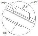
The bottom of the sliding plate 40 is symmetrically provided with four sliding saddles 401, the top of the lifting plate 30 is symmetrically provided with two guide rails 300, each two sliding saddles 401 are slidably connected with one guide rail 300, each guide rail 300 is provided with a sliding groove for the sliding of the sliding saddles 401, two ends of each guide rail 300 are provided with mounting holes, two ends of each guide rail 300 are fixedly connected with limiting blocks, wherein the outer walls of the two sliding saddles 401 are respectively provided with a displacement sensor 402, each displacement sensor 402 is electrically connected with the controller 2, when the sliding plate 40 slides on the tops of the two guide rails 300, the sliding grooves play a limiting role to ensure the stable sliding of the sliding plate 40, when the sliding plate 40 slides to one end close to the servo motor 410, one displacement sensor 402 detects the sliding distance of the sliding saddles 401 close to the servo motor 410 in real time, and when the machining precision is met, signals are transmitted to the controller 2, thereby outage servo motor 410, stop the slip of slide 40, when slide 40 slides to the one end of keeping away from servo motor 410, the sliding distance of saddle 401 of servo motor 410 is kept away from to another displacement sensor 402 real-time detection, when satisfying the machining precision, give controller 2 with signal transmission, thereby outage servo motor 410, stop the slip of slide 40, and then realize the multi-direction horizontal slip's of accurate regulation slide 40 displacement distance, improve wheel hub's machining precision, further promote wheel hub's processingquality, be favorable to promoting the product quality.
The top of the fixed block 522 is provided with an accommodating groove, the inside of the accommodating groove is provided with a buffer block 523 in an attaching manner, the top of the buffer block 523 is provided with a second anti-skid pad in an attaching manner, the bottom of the buffer block 523 and the inner bottom of the accommodating groove are symmetrically provided with eight butt-joint blocks, a telescopic spring 524 is fixedly connected between every two butt-joint blocks, as the wheel hub is made of metal materials and has a certain dead weight, and the pressing action of the pressing block 521 is added, the buffer block 523 is designed at the top of the fixed block 522, when the wheel hub is placed on the fixed block 522, the four telescopic springs 524 are contracted to drive the buffer block 523 to be contracted to the inside of the accommodating groove, so that the second anti-skid pad is driven to be downwards contracted to be flush with the surface of the fixed block 522, and further when the pressing block 521 presses the wheel hub, the pressure on the fixed block 522 is reduced, the effect of protecting the fixed block 522 is achieved, and the service life of the wheel hub is prolonged, the overall utility of the equipment is improved.
Two sliding blocks are symmetrically arranged at two ends of the lifting plate 30, two limiting grooves are symmetrically arranged on the inner wall of the rectangular groove, each sliding block is in sliding connection with one limiting groove, a limiting rod is vertically arranged in each limiting groove, each limiting rod is inserted and connected with the sliding block, a buffer spring 10 is sleeved on the outer wall of each limiting rod, the bottom of each sliding block and the inner bottom of each limiting groove are respectively abutted against two ends of one buffer spring 10, when the lifting plate 30 descends, the two sliding blocks slide down along with the lifting plate, as each limiting rod is sleeved with one buffer spring 10, the bottom of each sliding block and the inner bottom of each limiting groove are respectively abutted against two ends of one buffer spring 10, and as two ends of the lifting plate 30 are in sliding connection with the inner wall of the rectangular groove, the lifting plate 30 slides downwards in the rectangular groove, since the lifting plate 30 has many components, two buffer springs 10 are provided to protect the lifting plate 30 when it slides down.
The fixed first guard plate that is equipped with in top of mounting groove, rotation axis 530 and step motor 532 all pass first guard plate, the fixed second guard plate that is equipped with in top that leads to the groove, the top fixedly connected with articulated shaft of second guard plate, the fixed grafting that is equipped with in top of backup pad 50 is lived, the articulated shaft is articulated with the grafting post, be equipped with a plurality of radiating groove on two lateral walls of processing platform 1, the bottom of processing platform 1 is the symmetry and is provided with four supporting legss, and first guard plate is used for protecting the inside spare part of base station 400, and the inside spare part of groove is led in the protection of second guard plate, and the cooperation of articulated shaft and grafting post can guarantee to place frame 51 and base station 400 and rotate smoothly between backup pad 50, and the radiating groove is favorable to reducing the heat when equipment functions, and the supporting legs is used for supporting equipment.
A processing device and a working method for synchronously processing two sides of an aluminum alloy hub comprise the following steps:
s1: fixing the hub:
the wheel hub is vertically placed at the top of the fixing block 522 through manual work, then the double-shaft air cylinder 520 is started through the controller 2, so that the output end of the double-shaft air cylinder extends downwards, one end, close to the wheel hub, of the pressing block 521 is driven to extend out to be matched with the fixing block 522 to fix the wheel hub inside the placing frame 51, subsequent machining is facilitated, the first anti-slip pad plays a role in increasing friction force between the pressing block 521 and the surface of the wheel hub, the wheel hub is prevented from slipping during machining, meanwhile, the pressing block 521 is prevented from scratching the surface of the wheel hub, a protection effect is achieved, and the machining quality of the wheel hub is improved.
Because wheel hub is made by the metal material, itself possesses certain dead weight, the effect of pushing down of compact heap 521 in addition, therefore at the top design buffer block 523 of fixed block 522, when wheel hub put fixed block 522 on, four expanding spring 524 shrink, thereby drive the inside that buffer block 523 shrink to the holding tank, therefore it contracts to and fixed block 522 surface parallel and level to drive the second slipmat down, and then when making compact heap 521 compress tightly wheel hub, the pressure that fixed block 522 received obtains reducing, play the effect of protection fixed block 522, be favorable to prolonging its life, lifting means's whole practicality.
S2: adjusting the hub station:
in the course of working of wheel hub, according to its processing requirement, need adjust its station often to satisfy the process of punching or polishing of different positions, when the station of wheel hub needs to be reduced, start jacking subassembly 31 through controller 2, and then drive lifter plate 30 and glide in the inside of rectangle recess, until the adjustment requirement of the station of satisfying wheel hub.
In the processing process of the wheel hub, according to the processing requirements, the wheel hub sometimes needs to slide horizontally to meet the processing requirements of the surface of the wheel hub with equal distance, such as equal distance punching hole positions or grinding positions, when the wheel hub needs to slide horizontally, the controller 2 starts the traction assembly 41 to drive the sliding plate 40 to slide horizontally on the top of the lifting plate 30, when the sliding plate 40 slides to one end far away from the servo motor 410, one displacement sensor 402 detects the sliding distance of the saddle 401 close to the servo motor 410 in real time, when the processing precision is met, a signal is transmitted to the controller 2, so that the servo motor 410 is powered off, the sliding of the sliding plate 40 is stopped, when the sliding plate 40 slides to one end far away from the servo motor 410, the other displacement sensor 402 detects the sliding distance of the saddle 401 far away from the servo motor 410 in real time, when the processing precision is met, the signal is transmitted to the controller 2, thereby outage servo motor 410 stops the slip of slide 40, and then realizes the multi-direction horizontal slip's of accurate regulation slide 40 displacement distance, improves wheel hub's machining precision, further promotes wheel hub's processingquality, is favorable to promoting the product quality.
S3: and (3) processing synchronous machining of the hub:
after the single process of one side of the hub is finished, the stepping motor 532 is started through the controller 2, so that the driving rod 534 is driven to rotate through the output end of the device, the roller 535 and one end of the driving rod 534, which is far away from the stepping motor 532, are rotatably connected, the outer wall of the roller 535 is attached to the inner wall of the butt joint groove, the index plate 531 is rotatably connected with the base table 400 through the rotating shaft 530, the butt joint groove is integrally connected with the index plate 531, the top of the rotating shaft 530 is fixedly connected with the ground step for placing the frame 51, the rotating shaft 530 drives the placing frame 51 to rotate one hundred eighty degrees, the other side of the hub is rapidly rotated to a processing station, the other side of the hub is processed in the same single process as the previous one, and the process is repeated until all the processing processes of the two sides of the hub are finished, and the synchronous processing of the two sides of the hub is further realized.
The synchronous processing mode of the two sides of the hub provided by the embodiment is that after the single procedure of one side of the hub is finished, the hub is immediately rotated by one hundred eighty degrees through the placing frame 51, the single procedure processing of the other side of the hub, which is the same as the previous single procedure, is carried out, all processing procedures of one side of the hub are not completed before all processing procedures of the other side of the hub are carried out, and the processing mode provided by the embodiment is favorable for reducing processing errors caused by adjustment of stations of the hub and the like.
The working principle of the invention is as follows: when the hub is machined, the hub is vertically placed at the top of the fixing block 522 manually, then the double-shaft cylinder 520 is started through the controller 2, so that the output end of the double-shaft cylinder extends downwards, the pressing block 521 is driven to extend out towards one end close to the hub to be matched with the fixing block 522 to fix the hub in the placing frame 51, further, the subsequent machining is facilitated, the first anti-slip pad plays a role in increasing the friction force between the pressing block 521 and the surface of the hub, the hub is prevented from slipping during machining, meanwhile, the pressing block 521 is prevented from rubbing against the surface of the hub to play a protection role, the machining quality of the hub is improved, the hub is made of a metal material and has a certain self weight, and the pressing effect of the pressing block 521 is added, so that the buffer block 523 is designed at the top of the fixing block 522, when the hub is placed on the fixing block, the four telescopic springs 524 shrink, so that the buffer block 523 is driven to shrink into the accommodating groove 522, therefore, the second anti-skid pad is driven to be contracted to be flush with the surface of the fixing block 522, so that when the pressing block 521 presses the wheel hub, the pressure applied to the fixing block 522 is reduced, the effect of protecting the fixing block 522 is achieved, the service life of the fixing block 522 is prolonged, and the overall practicability of the equipment is improved.
In the processing process of the hub, according to the processing requirement, the stations of the hub are required to be adjusted frequently to meet the punching or polishing procedures of different positions, when the stations of the hub are required to be lowered, the driving motor 310 is started through the controller 2, so that the driving wheel 313 is driven to rotate through the output end of the driving motor, the driven wheel 315 is sleeved with the driven wheel 315 through the belt 316, the driven wheel 315 is sleeved with one end of the bidirectional screw 311, so that the bidirectional screw 311 is driven to rotate, because the two sliding sleeves 314 are respectively in threaded connection with two ends of the bidirectional screw 311, each sliding sleeve 314 is hinged with the bottom of the lifting plate 30 through the two ejector rods 312, the lifting plate 30 is driven to slide downwards in the rectangular groove through the four ejector rods 312 until the adjustment requirement of the stations of the hub is met, when the lifting plate 30 descends, the two sliding blocks slide downwards along with the lifting plate, because each limiting rod is sleeved with one buffer spring 10, the bottom of every slider and the inboard bottom of every spacing groove are contradicted with a buffer spring 10's both ends respectively, and because the both ends of lifter plate 30 and the inner wall sliding connection of rectangle recess again, therefore make lifter plate 30 slide downwards in the rectangle recess is inside, because the spare part of design is numerous on the lifter plate 30, therefore design two buffer spring 10, when the lifter plate 30 gliding, protect it.
In the processing process of the wheel hub, according to the processing requirements of the wheel hub, the wheel hub needs to slide horizontally sometimes to meet the processing requirements of the surface of the wheel hub at equal intervals, such as hole positions or grinding positions at equal intervals, when the wheel hub needs to slide horizontally, the servo motor 410 is started through the controller 2 to drive the first connecting rod 411 on the output end of the wheel hub to rotate, so that the second connecting rod 412 is driven to rotate through the first connecting rod 411, because the second connecting rod 412 is hinged between the first connecting rod 411 and the sliding plate 40 through two connecting blocks, the sliding plate 40 is arranged at the top of the lifting plate 30 in a sliding mode, and the sliding plate 40 is driven to slide horizontally at the top of the lifting plate 30 until the processing requirements of the wheel hub are met.
When the sliding plate 40 slides on the tops of the two guide rails 300, the sliding grooves play a role in limiting, so that the sliding plate 40 can slide stably, when the sliding plate 40 slides to one end close to the servo motor 410, one displacement sensor 402 detects the sliding distance of the saddle 401 close to the servo motor 410 in real time, when the machining precision is met, a signal is transmitted to the controller 2, so that the servo motor 410 is powered off, the sliding of the sliding plate 40 is stopped, when the sliding plate 40 slides to one end far away from the servo motor 410, the other displacement sensor 402 detects the sliding distance of the saddle 401 far away from the servo motor 410 in real time, when the machining precision is met, the signal is transmitted to the controller 2, so that the servo motor 410 is powered off, the sliding of the sliding plate 40 is stopped, so that the displacement distance of the multi-direction horizontal sliding of the sliding plate 40 can be accurately adjusted, the machining precision of the hub is improved, and the machining quality of the hub is further improved, is beneficial to improving the product quality.
After the single process of one side of the hub is finished, the controller 2 starts the stepping motor 532, so that the output end of the controller drives the driving rod 534 to rotate, the roller 535 is rotatably connected with one end of the driving rod 534 far away from the stepping motor 532, the outer wall of the roller 535 is attached to the inner wall of the butt-joint groove, the index plate 531 is rotatably connected with the base table 400 through the rotating shaft 530, the butt-joint groove is integrally connected with the index plate 531, the top of the rotating shaft 530 is fixedly connected with the ground of the placing frame 51, the placing frame 51 is driven to rotate one hundred eighty degrees through the rotating shaft 530, the other side of the hub is rapidly rotated to a processing station, the other side of the hub is processed in the same single process as the previous one, and so on, until all the processing processes of the two sides of the hub are finished, further, the synchronous processing of the two sides of the hub is realized, and the driving rod 534 is fixedly connected with the limiting plate 533, therefore, the limiting disc 533 rotates along with the driving rod 534 to limit the dividing disc 531, so as to ensure the stable rotation of the dividing disc 531 and further ensure the stable rotation of the placing frame 51.
The synchronous processing mode of the two sides of the hub provided by the embodiment is that after the single procedure of one side of the hub is finished, the hub is immediately rotated by one hundred eighty degrees through the placing frame 51, the single procedure processing of the other side of the hub, which is the same as the previous single procedure, is carried out, all processing procedures of one side of the hub are not completed before all processing procedures of the other side of the hub are carried out, and the processing mode provided by the embodiment is favorable for reducing processing errors caused by adjustment of stations of the hub and the like.