CN111573864A - Aeration tank for sewage treatment based on sludge siltation prevention - Google Patents
Aeration tank for sewage treatment based on sludge siltation prevention Download PDFInfo
- Publication number
- CN111573864A CN111573864A CN202010457931.XA CN202010457931A CN111573864A CN 111573864 A CN111573864 A CN 111573864A CN 202010457931 A CN202010457931 A CN 202010457931A CN 111573864 A CN111573864 A CN 111573864A
- Authority
- CN
- China
- Prior art keywords
- aeration
- sludge
- pipes
- pipe
- sewage
- Prior art date
- Legal status (The legal status is an assumption and is not a legal conclusion. Google has not performed a legal analysis and makes no representation as to the accuracy of the status listed.)
- Withdrawn
Links
Images


Classifications
-
- C—CHEMISTRY; METALLURGY
- C02—TREATMENT OF WATER, WASTE WATER, SEWAGE, OR SLUDGE
- C02F—TREATMENT OF WATER, WASTE WATER, SEWAGE, OR SLUDGE
- C02F7/00—Aeration of stretches of water
-
- C—CHEMISTRY; METALLURGY
- C02—TREATMENT OF WATER, WASTE WATER, SEWAGE, OR SLUDGE
- C02F—TREATMENT OF WATER, WASTE WATER, SEWAGE, OR SLUDGE
- C02F3/00—Biological treatment of water, waste water, or sewage
- C02F3/02—Aerobic processes
- C02F3/12—Activated sludge processes
-
- Y—GENERAL TAGGING OF NEW TECHNOLOGICAL DEVELOPMENTS; GENERAL TAGGING OF CROSS-SECTIONAL TECHNOLOGIES SPANNING OVER SEVERAL SECTIONS OF THE IPC; TECHNICAL SUBJECTS COVERED BY FORMER USPC CROSS-REFERENCE ART COLLECTIONS [XRACs] AND DIGESTS
- Y02—TECHNOLOGIES OR APPLICATIONS FOR MITIGATION OR ADAPTATION AGAINST CLIMATE CHANGE
- Y02W—CLIMATE CHANGE MITIGATION TECHNOLOGIES RELATED TO WASTEWATER TREATMENT OR WASTE MANAGEMENT
- Y02W10/00—Technologies for wastewater treatment
- Y02W10/10—Biological treatment of water, waste water, or sewage
Abstract
The invention provides an aeration tank for sewage treatment based on sludge anti-sedimentation, which comprises an aeration sewage tank for sewage treatment, a dead-angle sludge breaking and scattering mechanism for clearing sludge sedimentation at dead angles and a foam sludge dissipation mechanism for promoting sludge dissipation in foam, wherein the dead-angle sludge breaking and scattering mechanism is arranged on the aeration sewage tank, and the foam sludge dissipation mechanism is arranged on the aeration sewage tank and the dead-angle sludge breaking and scattering mechanism, and relates to the field of sewage treatment. This aeration tank for sewage treatment based on siltation is prevented to mud often silts up position and problem in the aeration tank according to mud, designs out the special construction that can eliminate the mud siltation fast, and the abundant mixture of near mud is to sewage in to effectual solved general aeration tank for sewage treatment have dead angle mud siltation and come-up foam to carry the problem of mud siltation, mud influences the problem of the effect of mud in sewage treatment in-process performance at invalid local siltation.
Description
Technical Field
The invention relates to the technical field of sewage treatment, in particular to an aeration tank for sewage treatment based on sludge siltation prevention.
Background
In an aeration tank used in the sewage treatment process, aeration is utilized to provide oxygen for activated sludge in sewage, and simultaneously sewage and sludge are mixed to promote the sludge to be uniformly distributed in the sewage, so that the purification of the sewage is conveniently and quickly promoted, but the sludge often has two conditions of narrow space siltation and foam suspension siltation in the water, the narrow space siltation is caused by the existence of mixed dead angles, bubbles in the water are subjected to the resistance of a water body and directly rise, the dead angle sludge cannot be effectively impacted, the sludge siltation time is long, the use efficiency of the sludge is influenced, the other siltation is caused by the fact that the sewage contains a large amount of substances which easily generate foams, for example, when a large amount of detergent is contained, a large amount of foams are generated, the foams generate the floating effect, the sludge nearby can be adsorbed from the generating parts of the sewage, so that the sludge foams rise along with the rising, especially, pile up the siltation in the position that is close to the pond limit, in mud can not the inward-remittance sewage, influence the result of use of mud, at present to these two kinds of modes of siltation, the mode of mainly adopting increases artificial management and control on the one hand, reduce and to produce the foam material and sneak into in the sewage, adopt the periodic elimination to the mud of the foam of production and dead angle siltation, increase new mud again and carry out sewage treatment, this kind of mode can play the effect that does not hinder sewage treatment and go on, it is great to consume manpower and materials, high cost, general aeration tank for sewage treatment has the problem that dead angle mud siltation and upward floating foam carry the mud siltation, mud is in the effect that useless local siltation influences mud and play in sewage treatment process, so need a sewage treatment aeration tank for based on mud siltation.
Disclosure of Invention
Technical problem to be solved
Aiming at the defects of the prior art, the invention provides an aeration tank for sewage treatment based on sludge anti-sedimentation, which solves the problems that the aeration tank for sewage treatment in general x has sludge sedimentation at dead angles and sludge sedimentation carried by floating foam, and the sludge sedimentation at invalid places influences the function of the sludge in the sewage treatment process.
(II) technical scheme
In order to achieve the purpose, the invention is realized by the following technical scheme: the utility model provides an aeration tank for sewage treatment based on siltation is prevented to mud, is including being used for carrying out sewage treatment aeration effluent water sump, being used for driving the dead angle mud of dead angle mud siltation and breaking the mechanism and be used for promoting the foam sludge dissipation mechanism of mud dissipation in the foam, the broken mechanism that looses of dead angle mud sets up on aeration effluent water sump, foam sludge dissipation mechanism sets up on aeration effluent water sump and dead angle mud break the mechanism, four angles of inner wall in aeration effluent water sump are curved fillet shape.
Preferably, the dead angle sludge breaking and dispersing mechanism comprises a high-pressure air pump, a central air delivery pipe, four communicating air pipes, four corner air injection cavities, four power aeration pipes, a plurality of floating support aeration pipes and a sludge breaking shaking spring, wherein the high-pressure air pump is fixedly installed on the outer surface of the aeration sewage pool, the four corner air injection cavities are arranged on the aeration sewage pool, the four corner air injection cavities are located at the four corners of the aeration sewage pool, a control air pipe is fixedly connected to the top end of each corner air injection cavity, a control valve is fixedly installed on the control air pipe, the central air delivery pipe is fixedly connected to the central position of the inner wall of the aeration sewage pool, the four communicating air pipes are fixedly connected with the surface of the central air delivery pipe, the four communicating air pipes are communicated with the central air delivery pipe, the four communicating air pipes are in one-to-one correspondence with the four control air pipes, and one ends of the four communicating air pipes, far away from the central The four corners of the inner wall of the aeration sewage pool are provided with a plurality of inclined aeration ports, the inclined aeration ports are communicated with the angular air injection cavity, the output end of the high-pressure air pump is sleeved with a pressure air pipe, and one end of the pressure air pipe is sleeved with one end of the central air pipe.
Preferably, four power aeration pipes, four have been cup jointed to the bottom of center gas-supply pipe the dislocation aeration mouth has been seted up on the top of power aeration pipe, the inner wall of dislocation aeration mouth is the slope form, the incline direction of dislocation aeration mouth is opposite with the incline direction of slope aeration mouth, four dislocation aeration mouth on the power aeration pipe is facing to the edge of four aeration effluent water ponds.
Preferably, a plurality of floats support aeration pipe, a plurality of has been cup jointed to the bottom of center gas-supply pipe float support aeration pipe by four power aeration pipe equallys divide, a plurality of float support aeration pipe's top has been seted up and has been turned the air jet, a plurality of float the surface of support aeration pipe and four power aeration pipe's upper surface and seted up perpendicular aeration mouth, a plurality of the surface of floating support aeration pipe and two sides of four power aeration pipes have all seted up the hedging aeration mouth, a plurality of float support aeration pipe's surface and four power aeration pipe's upper surface and have all seted up a plurality of and float support the aeration mouth, float the inner wall that holds in the palm the aeration mouth and be the slope form, the inclination that is close to the aeration sewage pond inside limit wall floats support the aeration mouth is bigger.
Preferably, the position that the interior diapire of aeration effluent water sump is close to four corners is provided with the bearing, and the inner circle fixedly connected with rotation axis of bearing, the surperficial fixedly connected with of rotation axis fluctuate the blade, aeration effluent water sump's inner wall articulates there is a plurality of activity and shakes the pole, and the spring is trembled to the broken mud of fixedly connected with between each activity shakes the pole, broken mud trembles the broken mud steel brush of the fixed surface of spring, the surface of broken mud steel brush and aeration effluent water sump's inner wall sliding connection, broken mud trembles that the surface of spring articulates there is broken mud pricker.
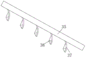
Preferably, the foam sludge dissipation mechanism comprises a circulating water injection cavity, a high-pressure water pump, four spray pipes, a plurality of pressure nozzles and four inclined crushing plates, the circulating water injection cavity is arranged on the edge of the aeration sewage pool, the spray pipes are fixedly connected to four edges of the aeration sewage pool, the spray pipes are communicated with the circulating water injection cavity, each spray pipe is fixedly provided with a plurality of pressure nozzles on the surface, the high-pressure water pump is fixedly arranged on the aeration sewage pool, the output end of the high-pressure water pump is sleeved with a pressure water pipe, and one end of the pressure water pipe penetrates through and extends to the inside of the circulating water injection cavity.
Preferably, the inclined crushing plates are fixedly connected to the communicating air pipes, the surfaces of the four inclined crushing plates correspond to the four spraying pipes, the surfaces of the inclined crushing plates are fixedly connected with a plurality of arc-shaped baffles, and the surfaces of the arc-shaped baffles are fixedly connected with a plurality of staggered crushing pyramid blocks.
(III) advantageous effects
(1) The sludge breaking and scattering mechanism is arranged, and the gas generated by aeration is utilized to initiate a plurality of structures to move together, so that the sludge breaking and shaking springs are promoted to shake at each dead angle of the sewage pool uninterruptedly and at high frequency, sludge can be prevented from being deposited at the dead angle, sludge blocks moving to the dead angle can be broken and suspended again along with the gas, and sludge can be prevented from being deposited at the dead angle.
(2) According to the invention, by arranging the foam sludge dissipation mechanism, the spray water is impacted on the staggered broken pyramid blocks and the arc-shaped baffle plates to form multi-layer sputtering, so that the foam in each area on the sewage surface can be dissipated by spraying, and the foam to which the sludge can adhere is reduced.
(3) According to the invention, the floating-support aeration port is arranged, an arc-shaped air bubble supporting film can be formed near the aeration sewage tank, sludge which easily sinks to the periphery from the position near the corner can be supported and is close to the lower part of the foam layer, the density of the sludge near the foam can be increased by the floating-supported sludge, the concentration of activated sludge near the foam is increased, the foam dissipation and the sinking and floating movement of the sludge are promoted, and the sludge deposited in the foam can be quickly dissipated under the combined action of the upper part and the lower part of the foam.
(4) According to the invention, a special structure capable of quickly eliminating sludge deposition is designed according to the position and the problem of frequent sludge deposition in the aeration tank, and nearby sludge is fully mixed into sewage, so that the problems of sludge deposition at dead corners and sludge deposition carried by floating foam in a common aeration tank for sewage treatment and the problem that sludge deposition at invalid places influences the function of sludge in the sewage treatment process are effectively solved.
Drawings
FIG. 1 is a schematic structural view of the present invention;
FIG. 2 is a top view of the aeration lagoon structure of the present invention;
FIG. 3 is a sectional view showing the structure of an aeration sewage tank according to the present invention;
FIG. 4 is a sectional view of a sloped breaker plate configuration of the present invention;
FIG. 5 is a cross-sectional view of the structure of the buoyant aeration tube of the present invention;
fig. 6 is a cross-sectional view of a dynamic aerator tube structure of the present invention.
Wherein, 1 aeration sewage pool, 2 dead angle sludge breaking mechanism, 21 high pressure air pump, 22 central air pipe, 23 communicating air pipe, 24 angle air spraying chamber, 25 power aeration pipe, 26 floating support aeration pipe, 27 sludge breaking and shaking spring, 28 control air pipe, 29 control valve, 210 inclined aeration port, 211 pressure air pipe, 212 dislocation aeration port, 213 turning air jet, 214 vertical aeration port, 215 flushing aeration port, 216 rotating shaft, 217 fluctuation blade, 218 movable shaking rod, 219 sludge breaking steel wire brush, 220 sludge breaking prick cone, 221 floating support aeration port, 3 foam sludge dissipating mechanism, 31 circulating water spraying chamber, 32 high pressure water pump, 33 spray pipe, 34 pressure nozzle, 35 inclined crushing plate, 36 pressure water pipe, 37 arc baffle, 38 crushing pyramid block.
Detailed Description
The technical solutions in the embodiments of the present invention will be clearly and completely described below with reference to the accompanying drawings of the present invention, and it is obvious that the described embodiments are only a part of the embodiments of the present invention, and not all of the embodiments. All other embodiments, which can be derived by a person skilled in the art from the embodiments given herein without making any creative effort, shall fall within the protection scope of the present invention.
As shown in fig. 1 to 6, an embodiment of the present invention provides an aeration tank for sewage treatment based on sludge anti-sedimentation, including an aeration wastewater tank 1 for sewage treatment, a dead angle sludge breaking mechanism 2 for removing dead angle sludge sedimentation, and a foam sludge dissipation mechanism 3 for promoting dissipation of sludge in foam, wherein the dead angle sludge breaking mechanism 2 is disposed on the aeration wastewater tank 1, the foam sludge dissipation mechanism 3 is disposed on the aeration wastewater tank 1 and the dead angle sludge breaking mechanism 2, and four corners of an inner wall of the aeration wastewater tank 1 are in an arc-shaped rounded angle shape.
Dead angle sludge breaking mechanism 2 includes high pressure air pump 21, central gas pipe 22, four intercommunication trachea 23, four angles spout air cavity 24, four power aeration pipes 25, a plurality of floats support aeration pipe 26 and broken mud tremble spring 27, high pressure air pump 21 fixed mounting is on aeration effluent water sump 1's surface, four angles spout air cavity 24 and set up on aeration effluent water sump 1, four angles spout air cavity 24 and are located four angles of aeration effluent water sump 1, the equal fixedly connected with a control trachea 28 in top of each angle spout air cavity 24, fixed mounting has control valve 29 on the control trachea 28, central gas pipe 22 fixed connection is on aeration effluent water sump 1's inner wall central point, four intercommunication trachea 23 all are connected with central gas pipe 22's fixed surface, four intercommunication trachea 23 and central gas pipe 22 intercommunication, four intercommunication trachea 23 and four control trachea 28 one-to-one, four intercommunication trachea 23 keep away from central gas pipe 22's one end all run through and extend to its corresponding control trachea 28 The inner part of the aeration sewage pool 1, a plurality of inclined aeration ports 210 are arranged at four corners of the inner wall of the aeration sewage pool 1, the inclined aeration ports 210 are communicated with the angle air injection cavity 24, the output end of the high pressure air pump 21 is sleeved with a pressure air pipe 211, one end of the pressure air pipe 211 is sleeved with one end of a central air pipe 22, four power aeration pipes 25 are sleeved at the bottom of the central air pipe 22, dislocation aeration ports 212 are arranged at the top ends of the four power aeration pipes 25, the inner wall of the dislocation aeration ports 212 is inclined, the inclination direction of the dislocation aeration ports 212 is opposite to that of the inclined aeration ports 210, the dislocation aeration ports 212 on the four power aeration pipes 25 face to the corners of the four aeration sewage pools 1, a plurality of floating aeration pipes 26 are sleeved at the bottom of the central air pipe 22, the plurality of floating aeration pipes 26 are equally divided by the four power aeration pipes 25, air injection ports 213 are arranged at the top ends of the plurality of the floating aeration, the surfaces of a plurality of floating aeration pipes 26 and the upper surfaces of four power aeration pipes 25 are provided with vertical aeration ports 214, the surfaces of the plurality of floating aeration pipes 26 and two sides of the four power aeration pipes 25 are provided with opposite aeration ports 215, the surfaces of the plurality of floating aeration pipes 26 and the upper surfaces of the four power aeration pipes 25 are provided with a plurality of floating aeration ports 221, the inner walls of the floating aeration ports 221 are inclined, the larger the inclination angle of the floating aeration ports 221 which are closer to the inner side wall of the aeration sewage tank 1 is, bearings are arranged at the positions, close to four corners, of the inner bottom wall of the aeration sewage tank 1, inner rings of the bearings are fixedly connected with a rotating shaft 216, the surface of the rotating shaft 216 is fixedly connected with a fluctuation blade 217, the inner wall of the aeration sewage tank 1 is hinged with a plurality of movable shaking rods 218, sludge breaking shaking springs 27 are fixedly connected between the movable shaking rods 218, the surface of the sludge breaking shaking springs 27 is fixedly connected with sludge breaking steel wire brushes 219, the surface of the mud breaking steel wire brush 219 is connected with the inner wall of the aeration sewage pool 1 in a sliding way, and the surface of the mud breaking trembler 27 is hinged with a mud breaking pricker 220.
The foam sludge dissipation mechanism 3 comprises a circulating water injection 31 cavity, a high-pressure water pump 32, four spray pipes 33, a plurality of pressure nozzles 34 and four inclined crushing plates 35, wherein the circulating water injection 31 cavity is arranged at the edge of the aeration sewage tank 1, the four edges of the aeration sewage tank 1 are fixedly connected with one spray pipe 33, the spray pipes 33 are communicated with the circulating water injection 31 cavity, the surface of each spray pipe 33 is fixedly provided with a plurality of pressure nozzles 34, the high-pressure water pump 32 is fixedly arranged on the aeration sewage tank 1, the output end of the high-pressure water pump 32 is sleeved with a pressure water pipe 36, one end of the pressure water pipe 36 penetrates through and extends into the circulating water injection 31 cavity, the inclined crushing plates 35 are fixedly connected on each communicating air pipe 23, the surfaces of the four inclined crushing plates 35 correspond to the four spray pipes 33, and the surfaces of the inclined crushing plates 35 are fixedly connected with a plurality of arc-shaped baffles, the surfaces of the arc-shaped baffles 37 are fixedly connected with a plurality of staggered crushing pyramid blocks 38.
When in use, the power supply is connected, the high-pressure air pump 21 and the high-pressure water pump 32 are started, the high-pressure air pump 21 inputs air into the central air pipe 22 through the pressure air pipe 211, part of the air enters the inside of the corner air injection cavity 24 through the communicating air pipe 23 and the control air pipe 28, then the air is sprayed out through each inclined aeration port 210 and is sprayed to the fluctuation blade 217 on one side of the rotating shaft 216, meanwhile, the air in the central air pipe 22 is transmitted to each power aeration pipe 25 and the floating aeration pipe 26, the part of the air transmitted to the inside of the power aeration pipe 25 is sprayed to the fluctuation blade 217 on the other side of the rotating shaft 216 through the staggered aeration ports 212, the fluctuation blade 217 rotates and touches the movable rod 218, the mud breaking shaking spring 27 is shaken from the top end of the mud breaking shaking spring 27 to drive the mud breaking steel wire brush 219 to brush dead corners, so as to avoid sludge sedimentation, and for some sludge lumps close to the sides can be penetrated small back and forth by the mud breaking cone 220, at this time, the gas sprayed from 213 can also impact and spray the sludge breaking shaking spring 27 to extrude the sludge breaking shaking spring 27 to make the sludge breaking shaking spring 27 extrude the sludge breaking steel wire brush 219, so that the sludge breaking steel wire brush 219 brushes the dead angle forcibly, the sludge close to the edge is influenced by the arc-shaped bubble film side formed by each floating support aeration port 221 when floating upwards to gradually climb up to be close to the bottom of the upper foam layer to increase the density of the sludge at the bottom of the foam, meanwhile, the water sprayed from the pressure water pipe 36 enters the inside of the circulating water spraying cavity 31 and is sprayed to each inclined crushing plate 35 through each pressure nozzle 34 on the spraying pipe 33, and the sprayed water is directly sprayed onto the foam or directly impacts the arc-shaped baffle 37 and the crushing pyramid block 38 to crush the foam and then is sprayed onto the foam, so that the upper foam layer is crushed, and the density of the foam is further crushed.
Claims (7)
1. The utility model provides an aeration tank for sewage treatment based on sludge siltation is prevented, includes and is used for carrying out sewage treatment aeration effluent water sump (1), is used for cleaing away dead angle mud that dead angle sludge siltation broken scattered mechanism (2) and is used for promoting foam sludge dissipation mechanism (3) of mud dissipation in the foam, its characterized in that: the dead angle sludge breaking and dispersing mechanism (2) is arranged on the aeration sewage tank (1), the foam sludge breaking mechanism (3) is arranged on the aeration sewage tank (1) and the dead angle sludge breaking and dispersing mechanism (2), and four corners of the inner wall of the aeration sewage tank (1) are arc-shaped fillets.
2. The aeration tank for sewage treatment based on sludge siltation prevention according to claim 1, wherein: the dead angle sludge breaking and dispersing mechanism (2) comprises a high-pressure air pump (21), a central air delivery pipe (22), four communicating air pipes (23), four corner air injection cavities (24), four power aeration pipes (25), a plurality of floating support aeration pipes (26) and sludge breaking shaking springs (27), wherein the high-pressure air pump (21) is fixedly arranged on the outer surface of the aeration sewage pool (1), the four corner air injection cavities (24) are arranged on the aeration sewage pool (1), the four corner air injection cavities (24) are positioned on the four corners of the aeration sewage pool (1), the top end of each corner air injection cavity (24) is fixedly connected with a control air pipe (28), the control air pipe (28) is fixedly provided with a control valve (29), the central air delivery pipe (22) is fixedly connected to the central position of the inner wall of the aeration sewage pool (1), and the four communicating air pipes (23) are fixedly connected with the surface of the central air delivery pipe (22), four intercommunication trachea (23) and central gas-supply pipe (22) intercommunication, four intercommunication trachea (23) and four control trachea (28) one-to-one, four the one end that central gas-supply pipe (22) were kept away from in intercommunication trachea (23) all runs through and extends as to the inside of its corresponding control trachea (28), a plurality of slope exposure mouth (210) have all been seted up to four corners of the inner wall of aeration effluent water sump (1), slope exposure mouth (210) and angle gas spray chamber (24) intercommunication, pressure gas-supply pipe (211) have been cup jointed to the output of high pressure air pump (21), the one end of pressure gas-supply pipe (211) cup joints with the one end of central gas-supply pipe (22).
3. The aeration tank for sewage treatment based on sludge siltation prevention according to claim 2, wherein: four power aeration pipe (25), four have been cup jointed to the bottom of center gas-supply pipe (22) dislocation aeration mouth (212) have been seted up on the top of power aeration pipe (25), the inner wall of dislocation aeration mouth (212) is the slope form, the incline direction of dislocation aeration mouth (212) is opposite with the incline direction of slope aeration mouth (210), four dislocation aeration mouth (212) on power aeration pipe (25) are to the edge of four aeration effluent water ponds (1).
4. The aeration tank for sewage treatment based on sludge siltation prevention according to claim 3, wherein: the bottom of the central gas transmission pipe (22) is sleeved with a plurality of floating support aeration pipes (26), the floating support aeration pipes (26) are equally divided by four power aeration pipes (25), the top ends of the floating support aeration pipes (26) are provided with turning air nozzles (213), the surfaces of the floating support aeration pipes (26) and the upper surfaces of the four power aeration pipes (25) are provided with vertical aeration ports (214), the surfaces of the floating support aeration pipes (26) and two side surfaces of the four power aeration pipes (25) are provided with hedging aeration ports (215), the surfaces of the floating support aeration pipes (26) and the upper surfaces of the four power aeration pipes (25) are provided with a plurality of floating support aeration ports (221), the inner wall of the floating support aeration port (221) is inclined, and the inclination angle of the floating support aeration port (221) which is closer to the inner side wall of the aeration sewage pool (1) is larger.
5. The aeration tank for sewage treatment based on sludge siltation prevention according to claim 4, wherein: the interior diapire of aeration effluent water sump (1) is provided with the bearing near the position of four corners, and the inner circle fixedly connected with rotation axis (216) of bearing, the fixed surface of rotation axis (216) is connected with undulant blade (217), the inner wall of aeration effluent water sump (1) articulates there is a plurality of activity and shakes pole (218), and the broken mud of fixedly connected with shakes between each activity shakes pole (218) and shakes spring (27), broken mud shakes broken mud brush (219) of the fixed surface of spring (27), the surface of broken mud brush (219) and the inner wall sliding connection of aeration effluent water sump (1), broken mud shakes that the surface of spring (27) articulates there is broken mud pricker (220).
6. The aeration tank for sewage treatment based on sludge siltation prevention according to claim 5, wherein: foam sludge dissipation mechanism (3) are including circulating water injection (31) chamber, high pressure water pump (32), four shower (33), a plurality of pressure nozzle (34) and four slope crushing shells (35), circulating water injection (31) chamber sets up on the edge of aeration effluent water sump (1), equal fixedly connected with shower (33) on four edges of aeration effluent water sump (1), shower (33) and circulating water injection (31) chamber intercommunication, each the equal fixed mounting in surface of shower (33) has a plurality of pressure nozzle (34), high pressure water pump (32) fixed mounting is on aeration effluent water sump (1), pressure water pipe (36) have been cup jointed to the output of high pressure water pump (32), the one end of pressure water pipe (36) is run through and is extended to the inside in circulating water injection (31) chamber.
7. The aeration tank for sewage treatment based on sludge siltation prevention according to claim 6, wherein: the inclined crushing plates (35) are fixedly connected to the communicating air pipes (23), the surfaces of the four inclined crushing plates (35) correspond to the four spraying pipes (33), the surfaces of the inclined crushing plates (35) are fixedly connected with a plurality of arc-shaped baffles (37), and the surfaces of the arc-shaped baffles (37) are fixedly connected with a plurality of staggered crushing pyramid blocks (38).
Priority Applications (1)
| Application Number | Priority Date | Filing Date | Title |
|---|---|---|---|
| CN202010457931.XA CN111573864A (en) | 2020-05-26 | 2020-05-26 | Aeration tank for sewage treatment based on sludge siltation prevention |
Applications Claiming Priority (1)
| Application Number | Priority Date | Filing Date | Title |
|---|---|---|---|
| CN202010457931.XA CN111573864A (en) | 2020-05-26 | 2020-05-26 | Aeration tank for sewage treatment based on sludge siltation prevention |
Publications (1)
| Publication Number | Publication Date |
|---|---|
| CN111573864A true CN111573864A (en) | 2020-08-25 |
Family
ID=72121481
Family Applications (1)
| Application Number | Title | Priority Date | Filing Date |
|---|---|---|---|
| CN202010457931.XA Withdrawn CN111573864A (en) | 2020-05-26 | 2020-05-26 | Aeration tank for sewage treatment based on sludge siltation prevention |
Country Status (1)
| Country | Link |
|---|---|
| CN (1) | CN111573864A (en) |
Cited By (3)
| Publication number | Priority date | Publication date | Assignee | Title |
|---|---|---|---|---|
| CN112830587A (en) * | 2021-01-21 | 2021-05-25 | 申朕光 | Aeration tank for sewage treatment |
| CN114275913A (en) * | 2021-12-28 | 2022-04-05 | 宜兴市惠众环保设备有限公司 | Low-power-consumption aeration oxygenation device for integrated sewage treatment |
| CN117509895A (en) * | 2024-01-05 | 2024-02-06 | 山东鲁北企业集团总公司 | Multistage treatment device for industrial wastewater |
Citations (15)
| Publication number | Priority date | Publication date | Assignee | Title |
|---|---|---|---|---|
| JP2006198478A (en) * | 2005-01-18 | 2006-08-03 | Kurimoto Ltd | Aerator and method for operating aeration tank |
| CN2805360Y (en) * | 2005-08-17 | 2006-08-16 | 王奇欣 | Energy-saving closed circulating pollution-discharge jet flow aeration breeding apparatus |
| EP2487139A1 (en) * | 2009-10-05 | 2012-08-15 | Asahi Kasei Chemicals Corporation | Additive used in a membrane-separation activated sludge process |
| CN203095713U (en) * | 2013-01-04 | 2013-07-31 | 上海友联竹园第一污水处理投资发展有限公司 | Horizontal type defoamer |
| CN104108802A (en) * | 2014-06-12 | 2014-10-22 | 杭州师范大学 | Autotrophic nitrogen removal granular sludge reactor capable of automatic floating-sludge smashing and circulating |
| CN104257047A (en) * | 2014-08-29 | 2015-01-07 | 浙江新光饰品股份有限公司 | Power failure protective device of claw chain manufacturing machine |
| CN106746188A (en) * | 2016-12-05 | 2017-05-31 | 海宁市丁桥镇芦湾股份经济合作社 | A kind of rural domestic sewage treatment system |
| CN207986812U (en) * | 2018-08-20 | 2018-10-19 | 山东蓝晓环境科技有限公司 | A kind of ponds Wastewater treatment AO |
| CN108928938A (en) * | 2018-07-05 | 2018-12-04 | 江阴市军协机械有限公司 | A kind of sewage treatment aerator |
| CN208200495U (en) * | 2018-04-09 | 2018-12-07 | 湖北三宁化工股份有限公司 | A kind of sewage treatment high-performance bio catalytic oxidation device |
| CN208933063U (en) * | 2018-09-11 | 2019-06-04 | 嘉兴市天伦纳米染整有限公司 | Defoaming device for aeration tank |
| CN209522721U (en) * | 2019-01-30 | 2019-10-22 | 河北邦普新能源科技有限公司 | A kind of Y-tubes automatic cleaning strainer |
| CN110668589A (en) * | 2019-10-10 | 2020-01-10 | 吴远光 | Waste water treatment air supporting machine |
| CN110952558A (en) * | 2019-12-13 | 2020-04-03 | 中建三局第一建设工程有限责任公司 | Automatic embedding device and system for pile foundation casing |
| CN111056591A (en) * | 2019-12-09 | 2020-04-24 | 鹏鹞环保股份有限公司 | Hydrocyclone for separating sediment deposited in biochemical pool |
-
2020
- 2020-05-26 CN CN202010457931.XA patent/CN111573864A/en not_active Withdrawn
Patent Citations (15)
| Publication number | Priority date | Publication date | Assignee | Title |
|---|---|---|---|---|
| JP2006198478A (en) * | 2005-01-18 | 2006-08-03 | Kurimoto Ltd | Aerator and method for operating aeration tank |
| CN2805360Y (en) * | 2005-08-17 | 2006-08-16 | 王奇欣 | Energy-saving closed circulating pollution-discharge jet flow aeration breeding apparatus |
| EP2487139A1 (en) * | 2009-10-05 | 2012-08-15 | Asahi Kasei Chemicals Corporation | Additive used in a membrane-separation activated sludge process |
| CN203095713U (en) * | 2013-01-04 | 2013-07-31 | 上海友联竹园第一污水处理投资发展有限公司 | Horizontal type defoamer |
| CN104108802A (en) * | 2014-06-12 | 2014-10-22 | 杭州师范大学 | Autotrophic nitrogen removal granular sludge reactor capable of automatic floating-sludge smashing and circulating |
| CN104257047A (en) * | 2014-08-29 | 2015-01-07 | 浙江新光饰品股份有限公司 | Power failure protective device of claw chain manufacturing machine |
| CN106746188A (en) * | 2016-12-05 | 2017-05-31 | 海宁市丁桥镇芦湾股份经济合作社 | A kind of rural domestic sewage treatment system |
| CN208200495U (en) * | 2018-04-09 | 2018-12-07 | 湖北三宁化工股份有限公司 | A kind of sewage treatment high-performance bio catalytic oxidation device |
| CN108928938A (en) * | 2018-07-05 | 2018-12-04 | 江阴市军协机械有限公司 | A kind of sewage treatment aerator |
| CN207986812U (en) * | 2018-08-20 | 2018-10-19 | 山东蓝晓环境科技有限公司 | A kind of ponds Wastewater treatment AO |
| CN208933063U (en) * | 2018-09-11 | 2019-06-04 | 嘉兴市天伦纳米染整有限公司 | Defoaming device for aeration tank |
| CN209522721U (en) * | 2019-01-30 | 2019-10-22 | 河北邦普新能源科技有限公司 | A kind of Y-tubes automatic cleaning strainer |
| CN110668589A (en) * | 2019-10-10 | 2020-01-10 | 吴远光 | Waste water treatment air supporting machine |
| CN111056591A (en) * | 2019-12-09 | 2020-04-24 | 鹏鹞环保股份有限公司 | Hydrocyclone for separating sediment deposited in biochemical pool |
| CN110952558A (en) * | 2019-12-13 | 2020-04-03 | 中建三局第一建设工程有限责任公司 | Automatic embedding device and system for pile foundation casing |
Cited By (4)
| Publication number | Priority date | Publication date | Assignee | Title |
|---|---|---|---|---|
| CN112830587A (en) * | 2021-01-21 | 2021-05-25 | 申朕光 | Aeration tank for sewage treatment |
| CN114275913A (en) * | 2021-12-28 | 2022-04-05 | 宜兴市惠众环保设备有限公司 | Low-power-consumption aeration oxygenation device for integrated sewage treatment |
| CN117509895A (en) * | 2024-01-05 | 2024-02-06 | 山东鲁北企业集团总公司 | Multistage treatment device for industrial wastewater |
| CN117509895B (en) * | 2024-01-05 | 2024-03-22 | 山东鲁北企业集团总公司 | Multistage treatment device for industrial wastewater |
Similar Documents
| Publication | Publication Date | Title |
|---|---|---|
| CN111573864A (en) | Aeration tank for sewage treatment based on sludge siltation prevention | |
| KR101857869B1 (en) | Surface Agitator of Self-Levitation | |
| KR101720901B1 (en) | Bubble generation device for the cistern on ground | |
| CN207973579U (en) | A kind of sewage aeration pond | |
| KR101162064B1 (en) | removes The moss and float of buoyant filter which uses the solar power | |
| KR100922174B1 (en) | Eliminating Apparatus of Floating matters and Organic Compound in Water Tank | |
| US20070267359A1 (en) | Aeration method of pool water and apparatus there of | |
| CN106614228B (en) | Low-frequency decontamination energy-saving fish tank for fragmentization of biochemical cotton | |
| JP2003117582A (en) | Water cleaning equipment | |
| JP4359399B2 (en) | Aquaculture water purification device | |
| KR101822782B1 (en) | Bubble generation device for the cistern on ground | |
| JP5360550B2 (en) | Aoko control method | |
| CN213326903U (en) | A purifier for river lake quality of water is ecological | |
| CN214232902U (en) | Sewage sand setting device and sewage purification system | |
| CN213266005U (en) | New material production sewage treatment plant | |
| CN210065369U (en) | Dissolved air flotation and precipitation integrated machine | |
| KR102280983B1 (en) | Water treatment device using plasma and microbubbles and water treatment method using the same | |
| KR101632021B1 (en) | Air Bubble Solution Apparatus | |
| KR20150118331A (en) | Scum Remove Apparatus of Length Variable Type | |
| WO2020232768A1 (en) | Microbubble oxygenation device based on turbulent gas mixing | |
| CN112830587A (en) | Aeration tank for sewage treatment | |
| CN207347246U (en) | It is a kind of to be used to handle the submersible sewage pump cavitation erosion of MBBR ponds, the device of blockage problem | |
| CN219621007U (en) | Purifying device for lake water quality and ecology | |
| JP2546379Y2 (en) | Ponds, lakes and other water purification systems | |
| CN2711139Y (en) | Novel and external placed type mechanical air-spreading and dissolving type air-floating column |
Legal Events
| Date | Code | Title | Description |
|---|---|---|---|
| PB01 | Publication | ||
| PB01 | Publication | ||
| SE01 | Entry into force of request for substantive examination | ||
| SE01 | Entry into force of request for substantive examination | ||
| WW01 | Invention patent application withdrawn after publication | ||
| WW01 | Invention patent application withdrawn after publication |
Application publication date: 20200825 |