CN111556799A - Lathe - Google Patents
Lathe Download PDFInfo
- Publication number
- CN111556799A CN111556799A CN201880085119.XA CN201880085119A CN111556799A CN 111556799 A CN111556799 A CN 111556799A CN 201880085119 A CN201880085119 A CN 201880085119A CN 111556799 A CN111556799 A CN 111556799A
- Authority
- CN
- China
- Prior art keywords
- tool
- spindle
- axis direction
- tools
- headstock
- Prior art date
- Legal status (The legal status is an assumption and is not a legal conclusion. Google has not performed a legal analysis and makes no representation as to the accuracy of the status listed.)
- Pending
Links
Images


Classifications
-
- B—PERFORMING OPERATIONS; TRANSPORTING
- B23—MACHINE TOOLS; METAL-WORKING NOT OTHERWISE PROVIDED FOR
- B23B—TURNING; BORING
- B23B3/00—General-purpose turning-machines or devices, e.g. centre lathes with feed rod and lead screw; Sets of turning-machines
- B23B3/30—Turning-machines with two or more working-spindles, e.g. in fixed arrangement
-
- B—PERFORMING OPERATIONS; TRANSPORTING
- B23—MACHINE TOOLS; METAL-WORKING NOT OTHERWISE PROVIDED FOR
- B23B—TURNING; BORING
- B23B13/00—Arrangements for automatically conveying or chucking or guiding stock
- B23B13/04—Arrangements for automatically conveying or chucking or guiding stock for turning-machines with a plurality of working-spindles
-
- B—PERFORMING OPERATIONS; TRANSPORTING
- B23—MACHINE TOOLS; METAL-WORKING NOT OTHERWISE PROVIDED FOR
- B23Q—DETAILS, COMPONENTS, OR ACCESSORIES FOR MACHINE TOOLS, e.g. ARRANGEMENTS FOR COPYING OR CONTROLLING; MACHINE TOOLS IN GENERAL CHARACTERISED BY THE CONSTRUCTION OF PARTICULAR DETAILS OR COMPONENTS; COMBINATIONS OR ASSOCIATIONS OF METAL-WORKING MACHINES, NOT DIRECTED TO A PARTICULAR RESULT
- B23Q39/00—Metal-working machines incorporating a plurality of sub-assemblies, each capable of performing a metal-working operation
- B23Q39/04—Metal-working machines incorporating a plurality of sub-assemblies, each capable of performing a metal-working operation the sub-assemblies being arranged to operate simultaneously at different stations, e.g. with an annular work-table moved in steps
- B23Q39/048—Metal-working machines incorporating a plurality of sub-assemblies, each capable of performing a metal-working operation the sub-assemblies being arranged to operate simultaneously at different stations, e.g. with an annular work-table moved in steps the work holder of a work station transfers directly its workpiece to the work holder of a following work station
-
- B—PERFORMING OPERATIONS; TRANSPORTING
- B23—MACHINE TOOLS; METAL-WORKING NOT OTHERWISE PROVIDED FOR
- B23Q—DETAILS, COMPONENTS, OR ACCESSORIES FOR MACHINE TOOLS, e.g. ARRANGEMENTS FOR COPYING OR CONTROLLING; MACHINE TOOLS IN GENERAL CHARACTERISED BY THE CONSTRUCTION OF PARTICULAR DETAILS OR COMPONENTS; COMBINATIONS OR ASSOCIATIONS OF METAL-WORKING MACHINES, NOT DIRECTED TO A PARTICULAR RESULT
- B23Q39/00—Metal-working machines incorporating a plurality of sub-assemblies, each capable of performing a metal-working operation
- B23Q2039/008—Machines of the lathe type
Abstract
The invention aims to provide a lathe which can easily recover chips around a tool rest. A lathe (1) is provided with headstock (10, 20), tool holders (40, 50), a support table (30), and drive units (U2, U3). The support table (30) movably supports the first tool holder (40) in the side portion (31). A first tool rest drive unit (U2) moves a first tool rest (40) in a first axial direction (Y1 axial direction) perpendicular to a center line (AX1) of a first main shaft (11). The second headstock drive unit (U3) moves the second headstock (20) in a second axial direction (X2 axial direction) which is perpendicular to the center line (AX1) of the first main shaft (11) and which is inclined with respect to the first axial direction (Y1 axial direction). A second tool rest (50) holding a second tool (T2) is positioned in a position not overlapping with the plurality of first tools (T1) in the third axis direction (X1 axis direction), and is positioned in a position overlapping with the plurality of first tools (T1) in a portion (range R1) of the second tool (T2) and on an extension line of the second tool (T2) in the center line direction (Z1 axis direction) of the first main shaft (11).
Description
Technical Field
The present invention relates to a lathe provided with a plurality of spindles.
Background
As a lathe, an NC (numerical control) lathe is known, which includes the following components: a front spindle head provided with a front spindle; a guide sleeve for supporting a workpiece protruding from the front spindle; a back spindle base provided with a back spindle which can be opposed to the front spindle through a guide sleeve; and a plurality of tool rests for processing the workpiece. The back spindle head is movable in a control axis direction orthogonal to the center line of the back spindle and in a control axis direction orthogonal to the center line of the front spindle. The plurality of tool holders mainly comprise: the main tool rest is used for processing the front side of the workpiece protruding from the guide sleeve; and a back processing tool rest for performing back processing on the workpiece fixed on the back main shaft. The main tool post holds a plurality of tools arranged in the control axis direction, and is supported to be movable in the control axis direction with respect to a support base on the front spindle side with respect to a front end of a workpiece protruding from the front spindle. The back surface processing tool rest holds a plurality of tools arranged in the control axis direction on the side closer to the back surface main shaft than the plurality of tools arranged in the control axis direction on the main tool rest. A space for allowing the main tool post to move exists between the support table and the back spindle tool post.
Further, the automatic lathe disclosed in patent document 1 includes: the 1 st main shaft can move linearly along the Z1 axis; the 1 st tool rest can move linearly along the X1 axis and the Y1 axis; the 2 nd main shaft can move linearly along the Z2 axis and the X3 axis; and a 2 nd tool post linearly movable along an X2 axis. Since the entire structure of the automatic lathe is disposed in an inclined manner, the X1 axis, the X2 axis, the X3 axis, and the Y1 axis are not in the horizontal direction nor in the vertical direction. The X1, X2, and X3 axes are parallel to each other, and the Y1 axis is orthogonal to the X1, X2, and X3 axes.
Background of the invention
Patent document
Patent document 1: international publication No. 2002/24386
Disclosure of Invention
[ problems to be solved by the invention ]
If a wide space for allowing the movement of the main tool post is provided between the support table of the main tool post and the rear spindle tool post, chips scattered from the workpiece are likely to accumulate in the space, and the chips in the space are difficult to collect. Even if the entire structure of the lathe is disposed in an inclined manner, if a wide space is provided between the support base and the back spindle holder, chips scattered from the workpiece are likely to accumulate in the space.
In addition, the problems described above are present in various lathes.
The invention discloses a lathe capable of easily recovering chips around a tool rest.
[ means for solving problems ]
The lathe of the present invention has an embodiment including: a first spindle table provided with a first spindle for holding a workpiece;
a first tool rest holding a plurality of first tools for machining a workpiece protruding from the first spindle;
a support table for movably supporting the first tool rest on a side closer to the first spindle than a front end of the workpiece protruding from the first spindle;
a first tool rest driving unit configured to move the first tool rest in a first axial direction orthogonal to a center line of the first spindle;
a second headstock on which a second spindle that receives a workpiece from the first spindle is provided at a position opposite to the first spindle;
a second headstock driving unit that moves the second headstock in a second axial direction orthogonal to a center line of the first main shaft and inclined with respect to the first axial direction; and
a second tool rest holding a second tool for machining the workpiece held by the second spindle; and is
The plurality of first tools are arranged along the first axis direction,
setting a direction orthogonal to a center line of the first main axis and the first axis direction as a third axis direction,
the second tool holder holding the second tool is located at a position not overlapping with the plurality of first tools in the third axis direction, and is located at a position overlapping with the plurality of first tools in the center line direction of the first spindle, the second tool and a portion on an extension line of the second tool.
[ Effect of the invention ]
According to the present invention, a lathe that can easily recover chips around a tool rest can be provided.
Drawings
Fig. 1 is a plan view schematically showing an example of the structure of a lathe.
Fig. 2 is a perspective view schematically showing an example of the appearance of a lathe.
Fig. 3 is a side view schematically showing an operation example of the first tool holder.
Fig. 4 is a side view schematically illustrating a main part of the lathe.
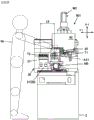
Fig. 5 is a front view schematically showing an example of a lathe.
Fig. 6 is a block diagram schematically showing an example of a circuit configuration of the lathe.
Fig. 7 is a side view schematically showing an example of the operation such as preparation.
Fig. 8 is a perspective view schematically showing an external appearance example of a lathe of a comparative example.
Fig. 9 is a side view schematically showing an example of operation of the first tool holder of the comparative example.
Fig. 10 is a front view schematically illustrating a lathe of a comparative example.
Fig. 11 is a side view schematically showing an example of operations such as preparation in the comparative example.
Detailed Description
Hereinafter, embodiments of the present invention will be described. Needless to say, the following embodiments are merely illustrative of the present invention, and all the features shown in the embodiments are not essential to the means for solving the problem of the present invention.
(1) Summary of the technology contained in the present invention:
first, an outline of the technique included in the present invention will be described with reference to fig. 1 to 11. The drawings of the present application are schematically illustrated, and the magnification in each direction shown in the drawings may be different, and the drawings may not be identical. Needless to say, each element of the present technology is not limited to the specific example shown by the symbol.
In the present case, the numerical range "Min to Max" means a minimum value Min or more and a maximum value Max or less.
[ form 1]
As illustrated in fig. 1 to 7, a lathe 1 according to one embodiment of the present invention includes a first headstock 10, a first tool rest 40, a support table 30, a first tool rest driving unit U2, a second headstock 20, a second headstock driving unit U3, and a second tool rest 50. The first headstock 10 is provided with a first spindle 11 that holds a workpiece W1. The first tool post 40 holds a plurality of first tools T1 for machining a workpiece W1 protruding from the first spindle 11. The support table 30 movably supports the first tool post 40 at a side portion 31 located closer to the first spindle 11 side than a front end W1a of a workpiece W1 protruding from the first spindle 11. The first tool rest drive unit U2 moves the first tool rest 40 in a first axial direction (for example, the Y1 axial direction) perpendicular to the center line AX1 of the first spindle 11. The second headstock 20 includes a second main spindle 21, and the second main spindle 21 receives a workpiece W0 from the first main spindle 11 at a position facing the first main spindle 11. The second headstock drive unit U3 moves the second headstock 20 in a second axial direction (for example, the X2 axial direction) perpendicular to the center line AX1 of the first main spindle 11 and inclined with respect to the first axial direction (the Y1 axial direction). The second tool post 50 holds a second tool T2 for machining a workpiece W2 held on the second spindle 21.
The plurality of first tools T1 are aligned in the first axial direction (Y1 axial direction).
Here, a direction orthogonal to the center line AX1 of the first main shaft 11 and the first axial direction (Y1 axis direction) is a third axial direction (for example, X1 axis direction). The second tool rest 50 holding the second tool T2 is located at a position not overlapping with the plurality of first tools T1 in the third axis direction (X1 axis direction), and is located at a position where a portion (for example, a range R1 shown in fig. 5) of the second tool T2 and an extension line of the second tool T2 overlaps with the plurality of first tools T1 in the center line direction (Z1 axis direction) of the first spindle 11.
First, an NC lathe 901 of a comparative example will be described with reference to fig. 8 to 11. Fig. 8 schematically illustrates the appearance of a lathe 901. Fig. 9 schematically illustrates the operation of the main tool rest 40 of the lathe 901 as viewed from the Z1 axis direction. Fig. 10 schematically illustrates the front of a lathe 901. Fig. 11 schematically illustrates operations such as preparation in a lathe 901.
The lathe 901 includes a front headstock 10, a guide bush 15, a rear headstock 20, a main tool post 40, a support table 30, a rear tool post 50, and various driving units U1 to U3 on a base 2. The front headstock drive unit U1 includes a feed mechanism 10Z and a Z1 axis motor M1, and moves the front headstock 10, on which the front spindle 11 is provided, in both directions in the Z1 axis direction. The Z1 axis direction is a horizontal direction along the center line AX1 of the front main shaft 11. The main blade carrier driving unit U2 includes feeding mechanisms 40X and 40Y, an X1 axis motor M2, and a Y1 axis motor (not shown), and moves the main blade carrier 40 in both directions of the X1 axis direction and the Y1 axis direction. The X1 axis is vertical and orthogonal to the Z1 axis. The Y1 axis is horizontal and orthogonal to the Z1 axis and the X1 axis. The rear headstock drive unit U3 includes feed mechanisms 20X and 20Z, an X2 axis motor (not shown), and a Z2 axis motor M5, and moves the rear headstock 20, on which the rear spindle 21 is provided, in both directions in the X2 axis direction and the Z2 axis direction. The Z2 axis direction is a horizontal direction along the center line AX2 of the rear main shaft 21 and is a horizontal direction along the Z1 axis direction. The X2 axis direction is a horizontal direction along the Y1 axis direction, and is orthogonal to the Z2 axis direction. The support table 30 holds the main tool post 40 on a side 31 facing the rear spindle 21 so as to be movable in the X1 and Y1 axial directions. A plurality of first tools are arranged in the Y1 axis direction on the lower surface of the main body portion 41 of the main holder 40. In the back tool holder 50, a plurality of second tools for back surface processing are arranged in the X2 axis direction on a surface (facing surface 51) facing the back surface spindle 21.
The upper stage of fig. 9 shows a state ST91 in which the main blade holder 40 is disposed at the moving end on the opposite side (right side in fig. 9) to the back blade holder 50 in the Y1 axis direction. In the lower stage of fig. 9, ST92 is shown in a state where the main blade holder 40 is disposed at the moving end on the side of the back blade holder 50 (left side of fig. 9) in the Y1 axis direction. The first tools T1 held by the main body 41 of the main tool post 40 are aligned in the horizontal direction orthogonal to the Z1 axis direction because the main tool post 40 moves in the horizontal Y1 axis direction. The second tool T2 held by the backing tool rest 50 is aligned in the horizontal direction orthogonal to the Z2 axis direction because it machines a workpiece held by the backing spindle 21 that moves in the horizontal X2 axis direction. Therefore, when the main blade holder 40 moves toward the rear blade holder 50 as viewed in the Z1 axis direction, the first tool T1 overlaps the second tool T2. Therefore, as shown in fig. 10, a clearance CL9 that allows passage of the first tool T1 held in the main blade holder 40 is formed at the back of the blade holder 50, that is, between the side portion 31 of the support table 30 and the blade holder 50.
If there is a wide clearance CL9 to the extent that the first tool T1 passes through, chips scattered from the workpiece by the main blade holder 40 machining the workpiece are likely to accumulate in the clearance CL 9. The chips accumulated in the clearance CL9 are difficult to directly recover. In order to recover the chips accumulated in the clearance CL9, it is necessary to provide a chip recovery groove or to flow a coolant in the clearance CL 9.
In the Z1 and Z2 axial directions, the machining point of the main tool post 40 and the machining point of the back tool post 50 are separated by the clearance CL9, and the stroke of the back headstock 20 is extended by that amount. If the stroke of the rear headstock 20 in the Z2 axis direction is long, the structure around the rear headstock 20 becomes large, the machine itself becomes large in size, and the cost also increases. Further, at the time of the work such as preparation, as shown in fig. 11, since the second tool T2 is horizontally arranged from the center line AX1 of the front main shaft 11 toward the worker Wr, it is accordingly difficult to reach the guide bush 15 or the like located at a deep position.
On the other hand, in the mode 1 of the present technology, as illustrated in fig. 3 and the like, a second axial direction (X2 axial direction) orthogonal to the center line AX1 of the first main shaft 11 is inclined with respect to the first axial direction (Y1 axial direction). Thus, the second tool rest 50 holding the second tool T2 can be provided at a position not overlapping the plurality of first tools T1 in the third axial direction (the X1 axial direction). By setting the positional relationship, as illustrated in fig. 5, in the center line direction (Z1 axis direction) of the first spindle 11, the second tool T2 and a portion (range R1) on an extension line of the second tool T2 in the second tool rest 50 holding the second tool T2 can be set to be positioned so as to overlap with the plurality of first tools T1. That is, since the second tool holder 50 is close to the side portion 31 of the support base 30 supporting the first tool holder 40, chips are less likely to enter between the side portion 31 of the support base 30 and the second tool holder 50. Therefore, the present embodiment 1 can provide a lathe that can easily recover chips around the second tool rest.
Further, the stroke of the second headstock can be shortened by bringing the second tool rest close to the side portion of the support table, and the structure constituting the periphery of the second headstock can be made small, which can reduce the cost. In addition, at the time of the work such as preparation, as illustrated in fig. 7, since the second tool is located at a position lower than the center line of the first main spindle, the guide bush or the like located at a deep position is easily accessed, and the operability is good. Further, in the case where a plurality of second tools are arranged in the second axial direction, the horizontal distance (L1 in fig. 7) from the position of the second tool to the first spindle center line is shorter than the horizontal distance (L9 in fig. 11) in the comparative example, so that the operability of preparation and the like can be improved from the above-described point of view.
Here, the first headstock may be fixed so as not to move, or may be movable in the direction of the center line of the first spindle. In addition, the workpiece protruding from the first spindle may be supported by the guide bush or may be machined without being supported by the guide bush.
The case of a tool holder holding a tool involves holding a tool unit with the tool by the tool holder.
The first tool post may hold a different tool than the first tool aligned in the first axial direction.
The support table can support the guide sleeve and also can support the first spindle.
The second headstock driving unit can move the second headstock in the direction of the center line of the second spindle in addition to the second axis direction.
The second axis direction is inclined with respect to the first axis direction means a direction in which the second axis direction is neither along the first axis direction nor a direction orthogonal to the first axis direction.
The second holder holding the second tool does not overlap with the plurality of first tools in the third axial direction, which means that the second tool does not overlap with the plurality of first tools in the third axial direction, and the second holder other than the second tool does not overlap with the plurality of first tools in the third axial direction.
The second tool holding the second tool is overlapped with the plurality of first tools in the direction of the center line of the first spindle, and the second tool and a portion located on an extension line of the second tool overlap with the plurality of first tools, which means at least one of the following cases 1 and 2.
(case 1) the second tool overlaps with the plurality of first tools in the direction of the center line of the first spindle.
(case 2) a portion of the second tool rest other than the second tool, which is located on an extension of the second tool in the center line direction of the first spindle, overlaps with the plurality of first tools in the center line direction of the first spindle.
[ form 2]
As illustrated in fig. 3 and the like, the first tool post 40 may hold a third tool T3, the third tool T3 being located at a position not overlapping in the first axial direction (Y1 axial direction) with the second tool post 50 holding the second tool T2. As illustrated in fig. 3, 4, etc., the second tool holder 50 holding the second tool T2 may be located at a position capable of overlapping with the third tool T3 in the third axis direction (X1 axis direction). This embodiment can improve the degree of freedom of machining while suppressing the size increase of the machine.
[ form 3]
As illustrated in fig. 1 and the like, the present machine tool 1 may further include a guide bush 15, and the guide bush 15 may pass through and support the workpiece W1 protruding from the first spindle 11. The first blade holder driving unit U2 may move the first blade holder 40 in the third axial direction (X1 axial direction) in addition to the first axial direction (Y1 axial direction). This form can improve the degree of freedom of processing.
In the following specific example, reference numeral 10 is used for the front headstock as an example of the first headstock, reference numeral 11 is used for the front spindle as an example of the first headstock, reference numeral 20 is used for the rear headstock as an example of the second headstock, reference numeral 21 is used for the rear spindle as an example of the second headstock, reference numeral 40 is used for the main tool post as an example of the first tool post, reference numeral 50 is used for the rear tool post as an example of the second tool post, reference numeral U2 is used for the main tool post driving unit as an example of the first tool post driving unit, and reference numeral 3 is used for the rear headstock driving unit as an example of the second headstock driving unit.
(2) Specific example of the structure of the lathe:
fig. 1 schematically illustrates a configuration of a spindle-moving NC (numerically controlled) lathe 1 as an example of a lathe. Fig. 2 schematically illustrates the appearance of the lathe 1. Fig. 3 schematically illustrates the operation of the main blade holder 40. Fig. 4 schematically illustrates a main part of the lathe 1. Fig. 5 is a front view schematically illustrating the lathe 1. The drawings referred to in this specification are only for illustrating the present technology and do not limit the present technology. The positional relationship between the respective portions is described as an example. Therefore, the present technology includes, for example, changing the left-right direction to the up-down direction or the front-back direction, changing the up-down direction to the left-right direction or the front-back direction, changing the front-back direction to the left-right direction or the up-down direction, or changing the rotation direction to the opposite direction. The same direction, position, and the like are not limited to strictly matching, and include a case where the directions and positions deviate from strictly matching due to an error.
A lathe 1 shown in fig. 1 and the like includes a front headstock 10, a guide bush 15, a rear headstock 20, a main tool post 40, a support table 30, a rear tool post 50, various driving units U1 to U3, and an NC device 70 on a base 2. The main parts of the various tables 2, 10, 20, 30, 40, 50, guide sleeves 15, and tools T1-T4 may be formed of metal, for example. The NC device 70 controls operations of the front headstock 10, the rear headstock 20, the main tool post 40, the driving units U1 to U3, and the like. The lathe 1 shown in fig. 2 and the like has X1, Y1, Z1, X2, and Z2 axes as control axes. The X1, Y1, Z1, X2, Z2 axis directions mean directions along X1, Y1, Z1, X2, Z2 axes. Further, the workpiece W0 shown in fig. 1 is a generic name of the workpiece W1 as the object of front-side processing and the workpiece W2 as the object of back-side processing.
The front headstock 10 provided with the front spindle 11 is movable relative to the base 2 in the Z1 axis direction along the center line AX1 of the front spindle 11. The Z1 axis direction shown in fig. 2 and the like is a horizontal direction. The NC apparatus 70 controls the position of the front headstock 10 in the Z1 axis direction via the front headstock drive unit U1. The front spindle 11 releasably holds a cylindrical (rod-shaped) workpiece W1 inserted in the Z1 axis direction by a chuck (not shown), and rotates the workpiece W1 about a spindle center line AX1 extending in the longitudinal direction of the workpiece W1.
The guide sleeve 15 is mounted on a support table 30 located in front of the front spindle 11. The guide bush 15 disposed in front of the front spindle 11 supports the long workpiece W1 penetrating through the front spindle 11 slidably in the Z1 axis direction, and is rotationally driven around the spindle center line AX1 in synchronization with the front spindle 11. That is, the guide bush 15 passes through and supports the workpiece W1 protruding from the front spindle 11. By providing the guide bush 15, the deflection of the elongated workpiece W1 is suppressed, and high-precision machining is performed.
The rear headstock 20 provided with the rear main shaft 21 is movable relative to the base 2 in a Z2 axis direction along a center line AX2 of the rear main shaft 21 and in an X2 axis direction (an example of a second axis direction) orthogonal to a main shaft center line AX 2. The Z2 axis direction is a direction along the Z1 axis direction. The Z2 axis direction shown in fig. 2 and the like is a horizontal direction. The X2 axis direction is not along the moving direction of the main blade holder 40, i.e., either the X1 or Y1 axis direction, but is inclined with respect to the horizontal Y1 axis direction (example of the first axis direction) or the vertical X1 axis direction (example of the third axis direction). The angle θ (see fig. 4) between the horizontal Y1 axis and the oblique X2 axis is not particularly limited, and may be, for example, about 10 to 80 °, about 20 to 70 ° with importance placed on the downsizing of the machine, or about 40 ° or less with importance placed on the height reduction of the machine.
The rear spindle 21 can move in the X2 axis direction through a position facing the front spindle 11 via the guide bush 15. As described with reference to fig. 2 and 4, the rear spindle 21 moves a portion descending from the center line AX1 of the front spindle 11 toward the front side (left side in fig. 4) in the X2 axis direction in both directions. The NC apparatus 70 controls the position of the rear headstock 20 in the X2 and Z2 axis directions via the rear headstock drive unit U3. The rear spindle 21 receives the workpiece W0 from the front spindle 11 at a position facing the front spindle 11 via the guide bush 15, and releasably holds the workpiece W2 inserted in the Z2 axis direction by a chuck (not shown). For example, if the front-side machined workpiece W2 is separated from the long workpiece W1 by the cutting blade held by the main blade holder 40, the back spindle 21 rotates the workpiece W2 about the spindle center line AX2 in the longitudinal direction of the workpiece W2.
The main tool post 40 is supported movably in the X1 and Y1 axial directions perpendicular to the center line AX1 of the front spindle 11 with respect to the side portion 31 of the support base 30 facing the rear spindle 21. The X1 axis direction (an example of the third axis direction) is the vertical direction and is orthogonal to the Z1 axis direction. The Y1 axis direction (an example of the first axis direction) is a horizontal direction and is orthogonal to the Z1 axis direction and the X1 axis direction. The NC apparatus 70 controls the position of the main tool post 40 in the X1 and Y1 axis directions via the main tool post driving unit U2.
As shown in fig. 2 and 4, the main blade holder 40 is a comb-shaped blade holder having: a body portion 41 holding a plurality of first tools T1; an extension 42 that holds a plurality of third tools T3; and a branch portion 43 holding a plurality of fourth tools T4.
The main body portion 41 has a face (facing face 41a) facing downward and opposing the backup holder 50 in the X1 axis direction, and a plurality of first tools T1 aligned in the Y1 axis direction are held on the facing face 41 a. Fig. 4 shows 6 first tools T1 including cutting blades and 3 drill bits, but the type and number of the first tools T1 are not limited to the example shown in fig. 4.
The extension portion 42 extends downward in the X1 axis direction from a portion (right side in fig. 4) of the opposing surface 41a that is on the opposite side from the back rest 50 with respect to the center line AX1 of the front main shaft 11 in the Y1 axis direction. The extension 42 has a surface (facing surface 42a) that can face the backup holder 50 in the Y1 axis direction, and a plurality of third tools T3 aligned in the X1 axis direction are held on the facing surface 42 a. Fig. 4 shows 3 drills as the third tool, but the type and number of the third tools T3 are not limited to the example shown in fig. 4. As shown in the lower section of fig. 3, the plurality of third tools T3 are located at the following positions: even if the main tool post 40 moves in the Y1 axis direction, it does not overlap the backup tool post 50 holding the plurality of second tools T2 for back processing in the Y1 axis direction.
As shown in fig. 2, the branch portion 43 protrudes from the facing surface 41a toward the rear main shaft 21 side and extends downward in the X1 axis direction between the arrangement of the first tools T1 and the extension portion 42. The branch portion 43 has a surface facing the side portion 31 of the support table 30 in the Z1 axis direction, and holds a plurality of fourth tools T4 aligned in the X1 axis direction on the facing surface. The fourth tools T4 are located at the following positions: even if the main tool post 40 moves in the Y1 axis direction, it does not overlap the backup tool post 50 holding the plurality of second tools T2 in the Y1 axis direction. Although not shown, the branch portion 43 may have a surface that can face the rear spindle 21 in the Z1 axis direction, and a plurality of tools arranged in the X1 axis direction can be held on the facing surface.
As described above, the main tool post 40 holds the plurality of tools T1, T3, and T4 for machining the workpiece W1 protruding from the front spindle 11 and penetrating the guide bush 15.
The support table 30 is fixed between the front headstock 10 and the rear headstock 20 so as not to move relative to the base 2, and extends upward from the base 2 in the X1 axis direction. The support table 30 holds a guide bush 15 through which a workpiece W1 protruding from the front spindle 11 passes. The side 31 of the support table 30 facing the back spindle 21 supports the main blade holder 40 so as to be movable in the X1 and Y1 axial directions, and is fixed so that the mounted back blade holder 50 does not move. The side 31 of the support table 30 is located closer to the front spindle 11 than the front end W1a of the workpiece W1 protruding from the front spindle 11 and penetrating the guide bush 15.
The backup holder 50 is fixed so as not to move relative to the side portion 31 of the support stand 30. The back tool holder 50 has a surface (facing surface 51) facing the back spindle 21, and holds a plurality of second tools T2 for back processing aligned in the X2 axis direction on the facing surface 51. Fig. 2 and 4 show 4 drills as the second tools T2, but the type and number of the second tools T2 are not limited to the example shown in fig. 2 and 4.
According to the above, the back tool post 50 holds the plurality of second tools T2 that machine the workpiece W2 held by the back spindle 21.
Further, a tool unit having a tool may be detachably attached to the main blade holder 40 and the backup blade holder 50. In this case, the tool is held by the tool holders 40, 50.
Further, the lathe 1 may be provided with a tool rest other than the tool rests 40 and 50.
Here, as shown in fig. 4 and 5, the backup holder 50 holding the plurality of second tools T2 is located at a position not overlapping the plurality of first tools T1 in the X1 axis direction. In the example shown in fig. 4, the upper limit (boundary B2) of the backup holder 50 holding the plurality of second tools T2 is located below the lower limit (boundary B1) of the movement range of the plurality of first tools T1 in the X1 axis direction. Therefore, the backup holder 50 holding the plurality of second tools T2 is located at a position not overlapping the plurality of first tools T1. This state is represented in the upper stage of fig. 3 as state ST 1.
The upper stage of fig. 3 shows a state ST1 in which the main blade holder 40 is disposed at the moving end on the opposite side (right side in fig. 3) to the back blade holder 50 in the Y1 axis direction. In the lower stage of fig. 3, ST2 is shown in a state where the main blade holder 40 is disposed at the moving end on the side of the back blade holder 50 (left side of fig. 3) in the Y1 axis direction. The first tools T1 held by the main body 41 of the main tool post 40 are aligned in the horizontal direction orthogonal to the Z1 axis direction because the main tool post 40 moves in the horizontal Y1 axis direction. The second tool T2 held by the back tool rest 50 is aligned in the X2 axis direction at a lower side than the plurality of first tools T1 in the X1 axis direction because it machines the workpiece held by the back spindle 21 moving in the X2 axis direction at a portion descending toward the front side. Therefore, even if the main blade holder 40 moves toward the back blade holder 50 when viewed in the Z1 axis direction, the first tool T1 does not overlap the second tool T2.
Therefore, as shown in fig. 5, the back surface of the back blade holder 50 can be attached to the side portion 31 of the support stand 30 at the back of the back blade holder 50, that is, without forming a gap between the side portion 31 of the support stand 30 and the back blade holder 50. As a result, the backup holder 50 holding the plurality of second tools T2 is positioned in the Z1 axis direction at a position where the plurality of second tools T2 and a portion (range R1) on an extension line of the plurality of second tools T2 overlap the plurality of first tools T1. The range R1 means a range from the back face of the backup blade holder 50 to the front end of the second tool T2 in the Z1 axial direction. Since there is the first tool T1 in the range R1 shown in fig. 5, in the backup holder 50 holding the plurality of second tools T2, the plurality of second tools T2 and a portion (range R1) on an extension line of the plurality of second tools T2 are located at positions overlapping with the plurality of first tools T1 in the Z1 axis direction.
As shown in the lower part of fig. 3, the plurality of third tools T3 held in the extension 42 of the main blade holder 40 are located at the following positions: even if the main tool post 40 moves in the Y1 axis direction, it does not overlap the backup tool post 50 holding the plurality of second tools T2 in the Y1 axis direction. In the example shown in the lower stage of fig. 3, the boundary B4 on the third tool T3 side of the back rest 50 holding the plurality of second tools T2 is located on the back rest 50 side with respect to the boundary B3 on the back rest 50 side in the movement range of the plurality of third tools T3 in the Y1 axis direction. Therefore, the plurality of third tools T3 are located at positions not overlapping the backup holder 50 holding the plurality of second tools T2.
Therefore, as shown in fig. 3 and 4, the backup 50 holding the second tool T2 may be arranged to be overlapped with the plurality of third tools T3 movable in the X1 axial direction. In the example shown in fig. 4, a plurality of third tools T3 are present below the upper limit (boundary B2) of the backup holder 50 holding a plurality of second tools T2 in the X1 axis direction. Therefore, the backup plate 50 holding the second tool T2 is located at a position where it can overlap with the plurality of third tools T3.
Next, a driving system of the lathe 1 will be described with reference to fig. 6 and the like. Fig. 6 schematically illustrates a circuit configuration of the NC lathe 1. In the lathe 1 shown in fig. 6, the NC device 70 is connected with an operation panel 80, a Z1-axis motor M1, an X1-axis motor M2, a Y1-axis motor M3, an X2-axis motor M4, a Z2-axis motor M5, a rotary motor (not shown) for the front spindle 11, a rotary motor (not shown) for the back spindle 21, a rotary motor (not shown) for the rotary drill, and the like. The NC device 70 includes a CPU (central processing Unit) 71, a ROM (Read Only Memory) 72 as a semiconductor Memory, a RAM (Random Access Memory) 73 as a semiconductor Memory, a timer circuit 74, an I/F (interface) 75, and the like. In fig. 6, the operation panel 80 is represented as I/F75 together with the I/fs of the servo motors M1 to M5. The interpretation executive program P1 for interpreting and executing the machining program P2 is written in the ROM 72. The RAM73 stores a machining program P2 created by the user. The machining program is also called an NC program. The CPU71 causes the computer to function as the NC apparatus 70 by executing the interpretive execution program P1 recorded in the ROM72, using the RAM73 as a workpiece area. Of course, a part or all of the functions realized by the interpretive executive P1 may be realized by other methods such as an ASIC (Application Specific Integrated Circuit).
The operation panel 80 includes an input unit 81 and a display unit 82, and functions as a user interface of the NC apparatus 70. The input unit 81 is configured by, for example, buttons or a touch panel for receiving operation input from an operator. The display unit 82 is configured by, for example, a display for displaying various settings received from the operator to the operation input and various information related to the NC lathe 1. The operator can cause the machining program P2 to be stored in the RAM73 using the operation panel 80 or an external computer.
As shown in fig. 2 and 6, the front headstock drive unit U1 includes a feed mechanism 10Z and a Z1 axis motor M1, and moves the front headstock 10, on which the front spindle 11 is provided, in both directions in the Z1 axis direction. The feed mechanism 10z is constituted by, for example, a pair of guide rails and a ball screw provided on the base 2, and a pair of guide members and a nut fixed to the bottom surface of the front headstock 10. Here, the guide members are slidably fitted to the respective guide rails, and nuts are screwed to the ball screws. If the Z1-axis motor M1 rotationally drives the ball screw in accordance with a command from the NC apparatus 70, the front headstock 10 moves in the Z1-axis direction with respect to the base 2.
Of course, the feed mechanism 10z may be configured to have a slidable fitting structure of a wedge groove and a wedge, instead of the slidable fitting structure of the guide rail and the guide member.
The main blade carrier driving unit U2 includes feeding mechanisms 40X and 40Y, an X1 axis motor M2, and a Y1 axis motor M3, and moves the main blade carrier 40 in both directions of the X1 axis direction and the Y1 axis direction. The feed mechanism 40x is constituted by, for example, a wedge groove and a ball screw disposed on the slide table 35 that slides in the Y1 axis direction, and a wedge and a nut disposed on the back surface (the front headstock 10 side) of the main tool rest 40. Here, the wedge is slidably fitted in the wedge groove, and the nut is screwed to the ball screw. If the X1-axis motor M2 rotationally drives the ball screw in accordance with a command from the NC apparatus 70, the main blade holder 40 moves in the X1-axis direction with respect to the support table 30 via the slide table 35. The feeding mechanism 40y is composed of, for example, a wedge groove and a ball screw disposed on the upper portion of the side portion 31 of the support table 30, and a wedge and a nut disposed on the back surface (the front headstock 10 side) of the slide table 35. Here, the wedge is slidably fitted in the wedge groove, and the nut is screwed to the ball screw. If the Y1-axis motor M3 rotationally drives the ball screw in accordance with a command from the NC apparatus 70, the main carriage 40 moves in the Y1-axis direction together with the slide table 35 with respect to the support table 30.
Of course, the feed mechanisms 40x and 40y may be configured to have a slidable fitting structure of a guide rail and a guide member, in addition to a slidable fitting structure of a wedge groove and a wedge. For example, the feeding mechanism 40x may be constituted by a pair of guide rails and a ball screw provided on the slide table 35, and a guide member and a nut fixed to the back surface of the main blade holder 40. The feeding mechanism 40y may be constituted by a pair of guide rails and a ball screw provided on the upper portion of the side portion 31 of the support table 30, and a guide member and a nut fixed to the back surface of the slide table 35.
The rear headstock drive unit U3 includes feed mechanisms 20X and 20Z, an X2 axis motor M4, and a Z2 axis motor M5, and moves the rear headstock 20, on which the rear spindle 21 is provided, in both directions in the X2 axis direction and the Z2 axis direction. The feed mechanism 20X is constituted by, for example, a pair of guide rails and a ball screw provided on the base 2, and a pair of guide members and a nut fixed to the bottom surface of the slide table 5 that slides in the X2 axis direction. Here, the guide members are slidably fitted to the respective guide rails, and nuts are screwed to the ball screws. If the X2-axis motor M4 rotationally drives the ball screw in accordance with a command from the NC apparatus 70, the rear headstock 20 moves in the X2-axis direction together with the slide table 5 with respect to the base 2. The feed mechanism 20z is constituted by, for example, a pair of guide rails and a ball screw provided on the slide table 5, and a pair of guide members and a nut fixed to the bottom surface of the rear headstock 20. Here, the guide members are slidably fitted to the respective guide rails, and nuts are screwed to the ball screws. If the Z2-axis motor M5 rotationally drives the ball screw in accordance with a command from the NC apparatus 70, the back headstock 20 moves in the Z2-axis direction with respect to the base 2 via the slide table 5.
Of course, the feed mechanisms 20x and 20z may be configured to have a slidable fitting structure of a wedge groove and a wedge, in addition to a slidable fitting structure of a guide rail and a guide member. For example, the feeding mechanism 20x may be constituted by a wedge groove and a ball screw disposed on the base 2, and a wedge and a nut disposed on the bottom surface of the slide table 5. The feed mechanism 20z may be composed of a wedge groove and a ball screw disposed on the slide table 5, and a wedge and a nut disposed on the bottom surface of the back headstock 20.
The machining control of the workpiece is performed as follows, for example.
First, the NC apparatus 70 holds the workpiece W1 in front of the front spindle 11, and projects the tip W1a from the guide bush 15 by a specific amount, and appropriately rotates and drives the workpiece W1 to drive the main tool post 40 to perform front machining. After the specific front machining, the NC apparatus 70 arranges the rear spindle 21 at a position where the center lines AX1 and AX2 are aligned, advances the workpiece W1 while holding the front spindle 11, and holds the front machined workpiece W2 on the rear spindle 21. The NC device 70 drives the main tool post 40 to separate the workpieces W1, W2 by the cutting blade, then appropriately rotationally drives the workpiece W2, drives the rear headstock 20, and drives the main tool post 40 as necessary to perform the rear surface processing. At this time. The back surface processing is performed by the second tool T2 held by the back blade holder 50. After the specific back surface processing, the NC apparatus 70 drives the back surface headstock 20 to a specific product discharge position, and discharges the back surface processed workpiece W2, that is, the product.
(3) Specific examples of the operation, action, and effect of the lathe:
as in the comparative example shown in fig. 8 to 11, if the main blade holder 40 is moved toward the side of the back blade holder 50 in the Y1 axis direction with the X2 axis direction set to the horizontal direction along the Y1 axis direction, the first tool T1 of the main blade holder 40 overlaps the second tool T2 of the back blade holder 50 (state ST92 in fig. 9). Therefore, as shown in fig. 10, a clearance CL9 that allows the first tool T1 held by the main tool post 40 to pass through is formed between the side portion 31 of the support base 30 and the back tool post 50, and chips of the workpiece are easily accumulated in the clearance CL 9.
On the other hand, in the specific example shown in fig. 1 to 6, the X2 axis direction perpendicular to the center line AX1 of the first main shaft 11 is inclined with respect to the horizontal Y1 axis direction. Therefore, as in the state ST2 of fig. 3, the backup holder 50 holding the plurality of second tools T2 can be provided at a position not overlapping the plurality of first tools T1 in the vertical X1 axis direction. According to this positional relationship, as shown in fig. 5, in the Z1 axis direction, the plurality of second tools T2 in the backup holder 50 holding the plurality of second tools T2 and the portion (range R1) on the extension line of the plurality of second tools T2 can be set to be positioned so as to overlap the plurality of first tools T1.
The backing block 50 shown in fig. 5 is mounted to the side 31 of the support block 30. Thus, there is no gap behind the back rest 50, and chips are not accumulated behind the back rest 50, thereby improving the chip recovery performance. Therefore, the specific example can easily recover the chips around the backup holder.
Since there is no gap behind the backup cutter holder 50, the machining point of the main cutter holder 40 is close to the machining point of the backup cutter holder 50 in the Z1 and Z2 axial directions. This specific example can thereby shorten the stroke of the rear headstock 20 in the Z2 axis direction, reduce the size of the structure constituting the periphery of the rear headstock 20, reduce the size of the machine itself, and reduce the cost.
Further, as in the comparative example shown in fig. 11, if the second tool T2 is horizontally arranged from the center line AX1 of the front main shaft 11 toward the worker Wr, the second tool T2 may block access to the guide bush or the like located at a deep position during operations such as preparation.
On the other hand, as in the present example shown in fig. 7, if the second tool T2 is arranged at a position lower than the center line AX1 of the front main shaft 11, the guide bush 15 and the like located at a deep position are easily accessed when the operator Wr performs a preparation or the like, and the operability is good. In addition, since the horizontal distance L1 from the position of the second tool T2 of the back tool holder 50 to the center line AX1 of the front spindle 11 is shorter than the horizontal distance L9 in the comparative example shown in fig. 11, the operability of preparation and the like is also improved in the above respect.
(4) Variation example:
various variations are contemplated by the present techniques.
For example, a lathe to which the present technology is applicable may be a lathe that does not have a guide bush and that machines a workpiece held by a spindle.
The back tool holder 50 is movable in a control axis direction perpendicular to the center line AX2 of the back spindle 21 and different from the X2 axis direction. In this case, an arrangement of 2 or more rows of the second tools T2 may be arranged in the backup holder 50. In addition, there may be one second tool T2 held in the backup holder 50 in the X2 axis direction.
Even when the front headstock does not move in the Z1 axis direction, the workpiece can be machined by moving the workpiece in the Z1 axis direction by holding the workpiece with the rear headstock aligned with the spindle center line and moving the rear headstock in the Z2 axis direction, for example. Even when the rear headstock does not move in the Z2 axis direction, the workpiece can be machined by moving the workpiece in the Z2 axis direction by holding the workpiece with the front headstock aligned with the spindle center line and moving the front headstock in the Z1 axis direction, for example. Even when the main tool post does not move in the X1 axis direction, the workpiece can be machined by moving the front headstock in the X1 axis direction, for example. Either case is encompassed in the present technology.
The mounting position of the back tool rest is not limited to the side of the support table, and may be the upper surface of the base. If there is no gap behind the back rest attached to the abutment, the chips are not accumulated behind the back rest, thereby improving the chip recovery performance. Even if there is a gap between the side of the support table and the back tool rest, if the gap is smaller than the wide gap CL9 shown in fig. 10, chips are less likely to enter between the side of the support table and the back tool rest. Therefore, the present embodiment 1 can obtain an effect of easily collecting chips around the back-up holder.
In addition, even if at least one of the third tool T3 and the fourth tool T4 is not provided in the main holder, the basic effect of easily collecting chips around the back holder can be obtained.
(5) To summarize:
as described above, according to the present invention, it is possible to provide a technology such as a lathe that can easily recover chips around a tool rest in various forms. Of course, even a technique including only the constituent elements of the independent claims can obtain the basic operation and effect described above.
Further, a configuration in which the respective configurations disclosed in the above examples are replaced or changed and combined with each other, and the like can be implemented. The present invention also includes the above-described configuration.
[ description of symbols ]
1 lathe
2 base station
10. 20 spindle platform
10z, 20x, 20z feeding mechanism
11. 21 spindle
15 guide sleeve
30 supporting table
31 side part
40. 50 knife rest
40x, 40y feeding mechanism
41 body part
42 extension
41a, 42a, 51 facing surface
AX1, AX2 centerline
Boundary B1-B4
R1 range
T1-T4 tool
U2 knife rest driving part
U3 headstock drive
W0, W1 and W2 workpieces
W1a front end
Claims (3)
1. A lathe is provided with:
a first spindle table provided with a first spindle for holding a workpiece;
a first tool rest holding a plurality of first tools for machining a workpiece protruding from the first spindle;
a support table for movably supporting the first tool rest on a side portion located closer to the first spindle than a front end of the workpiece protruding from the first spindle;
a first tool rest driving unit configured to move the first tool rest in a first axial direction orthogonal to a center line of the first spindle;
a second headstock on which a second spindle for receiving a workpiece from the first spindle is provided at a position facing the first spindle;
a second headstock driving unit that moves the second headstock in a second axial direction orthogonal to a center line of the first main shaft and inclined with respect to the first axial direction; and
a second tool rest holding a second tool for machining the workpiece held by the second spindle; and is
The plurality of first tools are arranged along the first axis direction,
setting a direction orthogonal to a center line of the first main axis and the first axis direction as a third axis direction,
the second tool holder holding the second tool is located at a position not overlapping with the plurality of first tools in the third axis direction, and is located at a position overlapping with the plurality of first tools in the center line direction of the first spindle, the second tool and a portion on an extension line of the second tool.
2. The lathe according to claim 1, wherein the first tool holder holds a third tool which is located at a position not overlapping with the second tool holder holding the second tool in the first axial direction; and is
The second tool holder holding the second tool is located at a position where it can overlap with the third tool in the third axial direction.
3. The lathe of claim 1 or 2, further provided with a guide sleeve passing through and supporting a workpiece protruding from the first spindle, and
the first blade holder driving unit moves the first blade holder in the third axial direction in addition to the first axial direction.
Applications Claiming Priority (3)
| Application Number | Priority Date | Filing Date | Title |
|---|---|---|---|
| JP2018031965A JP6880437B2 (en) | 2018-02-26 | 2018-02-26 | lathe |
| JP2018-031965 | 2018-02-26 | ||
| PCT/JP2018/047194 WO2019163280A1 (en) | 2018-02-26 | 2018-12-21 | Lathe |
Publications (1)
| Publication Number | Publication Date |
|---|---|
| CN111556799A true CN111556799A (en) | 2020-08-18 |
Family
ID=67687598
Family Applications (1)
| Application Number | Title | Priority Date | Filing Date |
|---|---|---|---|
| CN201880085119.XA Pending CN111556799A (en) | 2018-02-26 | 2018-12-21 | Lathe |
Country Status (6)
| Country | Link |
|---|---|
| US (1) | US20200368821A1 (en) |
| EP (1) | EP3733330A4 (en) |
| JP (1) | JP6880437B2 (en) |
| CN (1) | CN111556799A (en) |
| TW (1) | TWI763940B (en) |
| WO (1) | WO2019163280A1 (en) |
Citations (7)
| Publication number | Priority date | Publication date | Assignee | Title |
|---|---|---|---|---|
| JPH08118203A (en) * | 1994-10-25 | 1996-05-14 | Citizen Watch Co Ltd | Control method of nc lathe and device thereof |
| US20020102140A1 (en) * | 2000-12-15 | 2002-08-01 | Diethard Thomas | End milling cutter for machining workpieces made of a non-ferrous metal or plastic |
| US20030019336A1 (en) * | 2001-06-22 | 2003-01-30 | Traub Drehmaschinen Gmbh | Lathe |
| CN1454129A (en) * | 2000-09-22 | 2003-11-05 | 西铁城时计株式会社 | Automatic lathe |
| CN1509217A (en) * | 2001-05-15 | 2004-06-30 | ʱ���ӱ�ɷ�����˾ | Numerically controlled lath and method of machining work by this numerically controlled lath |
| EP1632309A1 (en) * | 2004-09-06 | 2006-03-08 | Tornos SA | Machining device with counterspindle in a multispindle lathe |
| CN1863631A (en) * | 2003-10-09 | 2006-11-15 | 星精密株式会社 | Automatic nc lathe |
Family Cites Families (4)
| Publication number | Priority date | Publication date | Assignee | Title |
|---|---|---|---|---|
| JPH055305U (en) * | 1991-04-08 | 1993-01-26 | セイコー精機株式会社 | Spindle moving type automatic lathe |
| JPH0557504A (en) * | 1991-09-03 | 1993-03-09 | Amada Co Ltd | Bar machining device |
| DE10131733A1 (en) * | 2001-06-22 | 2003-01-09 | Traub Drehmaschinen Gmbh | lathe |
| CN105817654B (en) * | 2016-05-31 | 2018-08-28 | 程泰机械(吴江)有限公司 | A kind of hard rail numerically controlled lathe |
-
2018
- 2018-02-26 JP JP2018031965A patent/JP6880437B2/en active Active
- 2018-10-18 TW TW107136732A patent/TWI763940B/en active
- 2018-12-21 CN CN201880085119.XA patent/CN111556799A/en active Pending
- 2018-12-21 WO PCT/JP2018/047194 patent/WO2019163280A1/en unknown
- 2018-12-21 EP EP18907279.6A patent/EP3733330A4/en active Pending
-
2020
- 2020-07-28 US US16/940,725 patent/US20200368821A1/en active Pending
Patent Citations (7)
| Publication number | Priority date | Publication date | Assignee | Title |
|---|---|---|---|---|
| JPH08118203A (en) * | 1994-10-25 | 1996-05-14 | Citizen Watch Co Ltd | Control method of nc lathe and device thereof |
| CN1454129A (en) * | 2000-09-22 | 2003-11-05 | 西铁城时计株式会社 | Automatic lathe |
| US20020102140A1 (en) * | 2000-12-15 | 2002-08-01 | Diethard Thomas | End milling cutter for machining workpieces made of a non-ferrous metal or plastic |
| CN1509217A (en) * | 2001-05-15 | 2004-06-30 | ʱ���ӱ�ɷ�����˾ | Numerically controlled lath and method of machining work by this numerically controlled lath |
| US20030019336A1 (en) * | 2001-06-22 | 2003-01-30 | Traub Drehmaschinen Gmbh | Lathe |
| CN1863631A (en) * | 2003-10-09 | 2006-11-15 | 星精密株式会社 | Automatic nc lathe |
| EP1632309A1 (en) * | 2004-09-06 | 2006-03-08 | Tornos SA | Machining device with counterspindle in a multispindle lathe |
Also Published As
| Publication number | Publication date |
|---|---|
| TWI763940B (en) | 2022-05-11 |
| JP2019147202A (en) | 2019-09-05 |
| JP6880437B2 (en) | 2021-06-02 |
| TW201936298A (en) | 2019-09-16 |
| EP3733330A4 (en) | 2021-09-22 |
| EP3733330A1 (en) | 2020-11-04 |
| WO2019163280A1 (en) | 2019-08-29 |
| US20200368821A1 (en) | 2020-11-26 |
Similar Documents
| Publication | Publication Date | Title |
|---|---|---|
| KR102190226B1 (en) | Machine tool with tool rest | |
| CN111093868B (en) | Lathe | |
| JP2005111631A (en) | Nc automatic lathe | |
| JP6807192B2 (en) | Machine Tools | |
| WO2001053024A1 (en) | Lathe with two-opposed spindles | |
| US20200180036A1 (en) | Lathe with tool unit mounted thereto | |
| JP2007075922A (en) | Multispindle lathe | |
| CN210209379U (en) | Turning and drilling integrated efficient numerical control lathe | |
| CN111556799A (en) | Lathe | |
| JP4382426B2 (en) | lathe | |
| JP4498631B2 (en) | Spindle movement type automatic lathe | |
| JP6405780B2 (en) | Machine Tools | |
| JPH0255161B2 (en) | ||
| CN113829065A (en) | Multi-task type work machine assembly | |
| KR100738390B1 (en) | Ultra narrow vertical machining center with column inside auto tool changer | |
| CN105058057A (en) | Row tool type numerically controlled lathe with combined machining function | |
| US10695842B2 (en) | Horizontal lathe machine with a mid-spindle and two tooling turrets | |
| CN208811554U (en) | Bracket for multi-shaft interlocked lathe | |
| JP2023077158A (en) | Machine tool | |
| JP2006255794A (en) | Automatic lathe | |
| CN115213687A (en) | Composite processing machine | |
| CN117483823A (en) | Machine tool | |
| KR20130077293A (en) | Machine tool having multiple spindle and table | |
| JP2005153084A (en) | Two-spindle opposed lathe |
Legal Events
| Date | Code | Title | Description |
|---|---|---|---|
| PB01 | Publication | ||
| PB01 | Publication | ||
| SE01 | Entry into force of request for substantive examination | ||
| SE01 | Entry into force of request for substantive examination | ||
| WD01 | Invention patent application deemed withdrawn after publication | ||
| WD01 | Invention patent application deemed withdrawn after publication |
Application publication date: 20200818 |