CN111499175A - Round glass cutting device - Google Patents
Round glass cutting device Download PDFInfo
- Publication number
- CN111499175A CN111499175A CN202010299500.5A CN202010299500A CN111499175A CN 111499175 A CN111499175 A CN 111499175A CN 202010299500 A CN202010299500 A CN 202010299500A CN 111499175 A CN111499175 A CN 111499175A
- Authority
- CN
- China
- Prior art keywords
- main shaft
- close
- roller
- output
- mounting seat
- Prior art date
- Legal status (The legal status is an assumption and is not a legal conclusion. Google has not performed a legal analysis and makes no representation as to the accuracy of the status listed.)
- Granted
Links
Images


Classifications
-
- C—CHEMISTRY; METALLURGY
- C03—GLASS; MINERAL OR SLAG WOOL
- C03B—MANUFACTURE, SHAPING, OR SUPPLEMENTARY PROCESSES
- C03B33/00—Severing cooled glass
- C03B33/02—Cutting or splitting sheet glass or ribbons; Apparatus or machines therefor
- C03B33/04—Cutting or splitting in curves, especially for making spectacle lenses
-
- Y—GENERAL TAGGING OF NEW TECHNOLOGICAL DEVELOPMENTS; GENERAL TAGGING OF CROSS-SECTIONAL TECHNOLOGIES SPANNING OVER SEVERAL SECTIONS OF THE IPC; TECHNICAL SUBJECTS COVERED BY FORMER USPC CROSS-REFERENCE ART COLLECTIONS [XRACs] AND DIGESTS
- Y02—TECHNOLOGIES OR APPLICATIONS FOR MITIGATION OR ADAPTATION AGAINST CLIMATE CHANGE
- Y02P—CLIMATE CHANGE MITIGATION TECHNOLOGIES IN THE PRODUCTION OR PROCESSING OF GOODS
- Y02P40/00—Technologies relating to the processing of minerals
- Y02P40/50—Glass production, e.g. reusing waste heat during processing or shaping
- Y02P40/57—Improving the yield, e-g- reduction of reject rates
Abstract
The invention relates to a cutting device, in particular to a circular glass cutting device. The technical problem to be solved is as follows: the utility model provides a device is tailor to circular glass that can realize that the automatic intermittent type nature of glass board removes, need not manual operation, improves and tailors efficiency. The technical scheme of the invention is as follows: a circular glazing device comprising: the side part of the mounting seat is provided with a motor, and the mounting seat close to one side of the motor is provided with a main shaft supporting frame; the output main shaft is rotatably arranged on the upper part of the main shaft supporting frame far away from one side of the motor, and the end part of the output main shaft close to one side of the motor penetrates through the main shaft supporting frame. The intermittent movement mechanism drives the strip-shaped glass plates to intermittently move, manual intermittent pushing of the strip-shaped glass plates is not needed, automatic cutting of the round glass is achieved through the cutting mechanism, and meanwhile, the conical cutting knife can automatically move upwards when the strip-shaped glass plates move under the action of the supporting rollers.
Description
Technical Field
The invention relates to a cutting device, in particular to a circular glass cutting device.
Background
Now, the workman tailors circular glass usually on rectangular shape glass sheet, the workman is to pressing and rotating the cutting knife, the cutting knife is thereupon made a circle on the glass sheet, circular glass is tailor out, after having tailor a circular glass, the workman stops to press the cutting knife, then promote rectangular shape glass sheet left, when the region that the glass sheet was not tailor is located the cutting knife below, the workman continues to press downwards and rotates the cutting knife, another circle is drawn on the glass sheet to the cutting knife, still another circular glass is tailor out, the workman repeats above operation, alright cut out the circular glass of polylith with rectangular shape glass sheet.
Above-mentioned circular glass board's mode is tailor to manual work needs workman's intermittent type nature to promote the glass board, and the distance that the manual work removed and lead to removing at every turn is different, can't guarantee the maximize utilizes bar glass, causes the shortcoming of the increase of glass waste material, needs to research and develop one kind and can make the automatic intermittent type nature of glass board remove, and glass board movement distance is the same, can effectively reduce the circular glass that glass waste material produced and tailor the device.
Disclosure of Invention
In order to overcome the defects that the maximum utilization of strip-shaped glass cannot be guaranteed, the cutting efficiency is low, and a glass plate needs to be pushed by manual work intermittently, the technical problem to be solved is as follows: the circular glass cutting device can enable the glass plate to move intermittently automatically, the moving distance of the glass plate is the same, and the generation of glass waste can be effectively reduced.
The technical scheme is as follows: a circular glass cutting device comprises:
the side part of the mounting seat is provided with a motor, and the mounting seat close to one side of the motor is provided with a main shaft supporting frame;
the output main shaft is rotatably arranged at the upper part of the main shaft supporting frame, and the end part of the output main shaft close to one side of the motor penetrates through the main shaft supporting frame;
the first belt assembly is arranged between the end part of the output main shaft close to one side of the motor and the output shaft of the motor;
the intermittent motion mechanism is arranged on the side part of the mounting seat close to one side of the main shaft supporting frame and the output main shaft;
and the cutting mechanism is arranged on the side part of the mounting seat close to one side of the output main shaft and is connected with the output main shaft.
As a further preferable mode, the intermittent motion mechanism includes:
a rotating rod is connected on the output main shaft at one side far away from the first belt component,
the tail end of the rotating rod is rotatably provided with a connecting rod;
the support plate is arranged on the side part of the mounting seat close to one side of the connecting rod, and the upper part of the side part of the support plate close to one side of the output main shaft is provided with an output rotating shaft through a one-way bearing;
the output rotating shafts on the two sides of the ratchet wheel are rotatably connected with the swinging plates, and the side parts of the swinging plates far away from one side of the ratchet wheel are rotatably connected with the tail ends of the connecting rods;
the circular top block is arranged between the swinging plates on the two sides in a sliding mode, a first spring is arranged between the side part of the circular top block, far away from one side of the supporting plate, and the side wall of the swinging plate, and the circular top block is matched with the ratchet wheel;
the side part of the mounting seat close to one side of the output main shaft is rotatably connected with the first roller, and a second belt assembly is arranged between the side part of the first roller close to one side of the ratchet wheel and the end part of the output rotating shaft close to the first roller;
and the second roller is rotatably arranged on the side part of the mounting seat far away from one side of the motor, and the conveyor belt is wound between the first roller and the second roller.
As a further preferable aspect, the cutting mechanism includes:
the mounting seat on one side, close to the first roller, of the n-type support frame is provided with the n-type support frame, and the middle of the top of the n-type support frame is rotatably connected with the small rotary drum;
the conical gears are arranged at the top of the small rotary drum and the end part of the output main shaft close to one side of the first roller, and the two conical gears are meshed;
the two sides below the top wall of the n-type support frame are both provided with a second spring, the small rotary drum is positioned between the second springs on the two sides, the tail end of the second spring is connected with a fixing plate, and the two sides of the top of the fixing plate penetrate through the top wall of the n-type support frame and are in sliding connection with the top wall;
the lifting rotating shaft is arranged in the small rotating drum in a sliding manner and is rotatably connected with the middle part of the fixed plate, a clamping rod is arranged at the upper part of the side wall of the lifting rotating shaft close to one side of the main shaft supporting frame, and the clamping rod is connected with the inner wall of the small rotating drum in a sliding manner;
the clamp plate, lift pivot lower part rotary type is connected with the clamp plate, and clamp plate and n type support frame sliding type are connected, and the lift pivot tip that is close to first cylinder one side is equipped with the toper cutting knife.
As a further preferable scheme, the device further comprises a cleaning mechanism, and the cleaning mechanism comprises:
the support rods are rotatably arranged on two sides of the side part of the mounting seat close to one side of the second roller, and a large-sized rotary drum is rotatably arranged between the upper parts of the support rods on the two sides;
the brush, a plurality of brushes are evenly installed in the large-scale rotary drum outside, install the third belt subassembly between the large-scale rotary drum lateral part that is close to backup pad one side and the output main shaft lateral part that is close to conveyer belt one side.
As a further preferable embodiment, the method further comprises:
and the supporting rollers are uniformly arranged on the outer side of the conveyor belt.
Compared with the prior art, the invention has the following advantages: 1. through intermittent motion mechanism, drive rectangular shape glass board intermittent type nature removal, need not artifical intermittent type nature and promote rectangular shape glass board to guarantee that the distance that rectangular shape glass board moved at every turn is the same, thereby can the maximize utilize rectangular shape glass board, reduce the production of glass waste material.
2. Through cutting mechanism, realize circular glass's automation and tailor, simultaneously, under the effect of supporting roller, can realize that rectangular shape glass board toper cutting knife moves up automatically when removing.
3. Through clearance mechanism, will tailor the glass piece that produces automatically and clear up, can prevent that the manual work from being pricked the hand by the glass piece when taking out circular glass.
Drawings
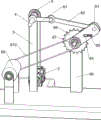
Fig. 1 is a schematic perspective view of the present invention.
Fig. 2 is a schematic perspective view of the motor, the spindle support, the output spindle, and the intermittent motion mechanism of the present invention.
Fig. 3 is a schematic perspective view of the present invention with a portion of the intermittent motion mechanism and the cleaning mechanism removed.
FIG. 4 is a schematic perspective view of the cleaning mechanism and the supporting roller according to the present invention.
FIG. 5 is a schematic perspective view of the bevel gear, the small drum, the clamping rod, the lifting spindle and the fixing plate of the present invention.
Fig. 6 is a schematic partial perspective view of the cutting mechanism of the present invention.
Wherein: 1-mounting seat, 2-motor, 3-spindle supporting frame, 4-output spindle, 5-first belt assembly, 6-intermittent motion mechanism, 61-rotating rod, 62-connecting rod, 63-swinging plate, 64-circular top block, 65-first spring, 66-supporting plate, 67-output rotating shaft, 68-ratchet wheel, 69-first roller, 610-second belt assembly, 611-second roller, 612-conveying belt, 7-cutting mechanism, 71-n type supporting frame, 72-small rotating cylinder, 73-bevel gear, 74-lifting rotating shaft, 741-clamping rod, 75-conical cutting knife, 76-fixing plate, 77-second spring, 78-pressing plate, 8-cleaning mechanism and 81-supporting rod, 82-large drum, 83-brush, 84-third belt assembly, 9-support roller.
Detailed Description
Although the present invention may be described with respect to particular applications or industries, those skilled in the art will recognize the broader applicability of the invention. Those of ordinary skill in the art will recognize other factors such as: terms such as above, below, upward, downward, and the like are used to describe the accompanying drawings and are not meant to limit the scope of the invention, which is defined by the appended claims. Such as: any numerical designation of first or second, and the like, is merely exemplary and is not intended to limit the scope of the invention in any way.
Example 1
The utility model provides a circular glass tailors device, as shown in fig. 1, including mount pad 1, motor 2, spindle support frame 3, output main shaft 4, first belt assembly 5, intermittent motion mechanism 6 and tailorring mechanism 7, mount pad 1 left side forward-mounted has motor 2, mount pad 1 left side front portion is equipped with spindle support frame 3, spindle support frame 3 is located the motor 2 right side, output main shaft 4 is connected to spindle support frame 3 upper portion rotary type, be equipped with first belt assembly 5 between motor 2's the output shaft and the 4 left ends of output main shaft, intermittent motion mechanism 6 sets up on mount pad 1's left side rear portion and output main shaft 4, mount pad 1 right part front side is provided with tailorring mechanism 7, tailorring mechanism 7 is connected with output main shaft 4.
When round glass needs to be cut, a long strip-shaped glass plate is placed on a conveying part of an intermittent motion mechanism 6, a cutting part in a cutting mechanism 7 is lifted upwards manually, the cutting part in the cutting mechanism 7 moves upwards along with the cutting part and is not in contact with the long strip-shaped glass plate, then a motor 2 is started, an output shaft of the motor 2 drives an output spindle 4 to rotate through a first belt component 5, the output spindle 4 drives the intermittent motion mechanism 6 to operate, the conveying part in the intermittent motion mechanism 6 intermittently rotates along with the cutting part, the conveying part in the intermittent motion mechanism 6 drives the long strip-shaped glass plate to intermittently move backwards, meanwhile, the output spindle 4 rotates to drive parts in the cutting mechanism 7 to rotate, and the cutting part in the cutting mechanism 7 rotates along with the conveying part; when the conveying part in the intermittent motion mechanism 6 stopped rotating, the rectangular shape glass board stopped moving, the position that does not cut on the rectangular shape glass board is located the below of the cutting part in the cutting mechanism 7, the part in the cutting mechanism 7 is loosened to the manual work, the pivoted cutting part in the cutting mechanism 7 moves down thereupon and contacts the rectangular shape glass board and cuts out a circular glass, after cutting out the completion, the manual work can lift the cutting part in the cutting mechanism 7 and separate with the rectangular shape glass board, then the intermittent motion mechanism 6 drives the rectangular shape glass board once more and moves one section distance backward and stops, so circulation, alright cut out the circular glass of polylith on the rectangular shape glass board.
Example 2
Generally, as shown in the diagrams of fig. 1 to 3 and fig. 5 to 6, the intermittent mechanism 6 includes a rotating rod 61, a connecting rod 62, a swinging plate 63, a circular top block 64, a first spring 65, a support plate 66, an output rotating shaft 67, a ratchet 68, a first roller 69, a second belt assembly 610, a second roller 611 and a conveyor belt 612, the rotating rod 61 is installed on the left side of the output spindle 4, the rotating rod 61 is located on the right side of the spindle support frame 3, the connecting rod 62 is rotatably connected to the end of the rotating rod 61, the support plate 66 is installed on the rear portion of the left side of the mounting base 1, the output rotating shaft 67 is connected to the upper portion of the support plate 66 through a one-way bearing, the ratchet 68 is installed on the output rotating shaft 67, the swinging plates 63 are rotatably installed on both sides of the ratchet 68, the rear ends of the connecting rod 62 are rotatably connected between the rear portions, all be connected with first spring 65 between the swing board 63 lateral wall of circular kicking block 64 rear side and both sides, circular kicking block 64 and ratchet 68 cooperation, the anterior rotary type in mount pad 1 right side is equipped with first cylinder 69, is connected with second belt assembly 610 between the left side of first cylinder 69 and the output pivot 67 right side, and mount pad 1 right side rear portion rotary type is provided with second cylinder 611, is equipped with conveyer belt 612 between first cylinder 69 and the second cylinder 611.
The long strip-shaped glass plate is placed on the conveyor belt 612, then the motor 2 is started, the output shaft of the motor 2 drives the output main shaft 4 to rotate, the output main shaft 4 drives the rotating rod 61 to rotate, the rotating rod 61 drives the connecting rod 62 to swing back and forth, and the connecting rod 62 drives the swing plate 63 to swing back and forth; since the output rotary shaft 67 is mounted on the support plate 66 through a one-way bearing, the ratchet 68 can rotate only in a single direction. When the swinging plate 63 swings backwards, the circular top block 64 swings backwards along with the swinging plate, so that the ratchet wheel 68 and the output rotating shaft 67 are driven to rotate, the output rotating shaft 67 drives the first roller 69 to rotate through the second belt assembly 610, the first roller 69 drives the second roller 611 to rotate through the conveyor belt 612, the conveyor belt 612 rotates along with the first roller, and the conveyor belt 612 drives the elongated glass plate to move backwards; when the swinging plate 63 moves forward, the swinging plate 63 rotates in a single direction due to the rotation of the output rotating shaft 67, and under the elastic force of the first spring 65, the swinging plate 63 drives the circular jacking block 64 to slide forward on the ratchet wheel 68, at the same time, the ratchet wheel 68 and the output rotating shaft 67 stop rotating, the conveyor belt 612 stops conveying the elongated glass plate, the elongated glass plate stops moving along with the elongated glass plate, meanwhile, the output shaft of the motor 2 drives the cutting component in the cutting mechanism 7 to rotate, when the conveyor belt 612 stops rotating, the elongated glass plate stops moving backwards, the cutting component in the cutting mechanism 7 is manually loosened downwards to enable the cutting component to contact with the elongated glass plate and cut a piece of circular glass, after the cutting is finished, the components in the cutting mechanism 7 are manually jacked upwards, the cutting component in the cutting mechanism 7 moves upwards along with the elongated glass plate to be separated from the contact, and then the swinging plate 63, the conveyor belt 612 starts to continue conveying, the strip-shaped glass plate continues to move backwards, when the conveyor belt 612 stops rotating again, the strip-shaped glass plate stops moving backwards again, the components in the cutting mechanism 7 are loosened manually, and the cutting component in the cutting mechanism 7 moves downwards to contact the strip-shaped glass plate and cuts out a piece of round glass again.
The cutting mechanism 7 comprises an n-type supporting frame 71, a small rotary drum 72, a bevel gear 73, a lifting rotary shaft 74, a conical cutter 75, a fixing plate 76, a second spring 77 and a pressing plate 78, the n-type supporting frame 71 is arranged at the front part of the right side of the mounting seat 1, the small rotary drum 72 is rotatably arranged in the middle of the top of the n-type supporting frame 71, the bevel gears 73 are arranged at the top of the small rotary drum 72 and the right side of the output main shaft 4 respectively, the two bevel gears 73 are meshed, the second springs 77 are connected to the left and right sides below the top wall of the n-type supporting frame 71, the small rotary drum 72 is positioned between the second springs 77 at the two sides, the fixing plate 76 is connected to the tail end of the second spring 77, the lifting rotary shaft 74 is connected to the small rotary drum 72 in a sliding manner, a clamping rod 741 is arranged at the upper part of, the pressing plate 78 is connected with the n-shaped supporting frame 71 in a sliding manner, and the front end of the lifting rotating shaft 74 is provided with a conical cutting knife 75.
When the motor 2 operates, the output shaft of the motor 2 drives the output spindle 4 to rotate, the output spindle 4 drives the bevel gear 73 on the right side to rotate, the bevel gear 73 on the top of the small drum 72 rotates along with the output spindle, the bevel gear 73 on the top of the small drum 72 drives the small drum 72 to rotate, and the small drum 72 drives the lifting rotating shaft 74 and the conical cutter 75 to rotate. Before the motor 2 is started, the pressing plate 78 is manually lifted upwards, the pressing plate 78 drives the fixing plate 76 to move upwards, the second spring 77 is compressed, the pressing plate 78 moves upwards to drive the lifting rotating shaft 74 and the conical cutter 75 to move upwards, and then the conical cutter 75 is separated from contact with the elongated glass plate. When the conveyor belt 612 stops rotating, the elongated glass plate stops moving backwards, the press plate 78 is manually loosened, the fixing plate 76 moves downwards under the action of the second spring 77, the fixing plate 76 drives the press plate 78 to move downwards, the lifting rotating shaft 74 and the conical cutter 75 move downwards along with the moving, the rotating conical cutter 75 contacts the elongated glass plate and cuts the elongated glass plate, the conical cutter 75 can move upwards again after the cutting is finished, and the hand is loosened when the elongated glass plate stops moving backwards again.
Example 3
Specifically, as shown in fig. 1 and 4, the cleaning device further includes a cleaning mechanism 8, the cleaning mechanism 8 includes a support rod 81, a large drum 82, brushes 83 and a third belt assembly 84, the support rods 81 are disposed on the left and right sides of the rear portion of the right side of the mounting base 1, the large drum 82 is rotatably mounted between the upper portions of the support rods 81 on the two sides, a plurality of brushes 83 are uniformly disposed on the outer side of the large drum 82, and the third belt assembly 84 is connected between the right side of the output spindle 4 and the left side of the large drum 82.
After the motor 2 is started, the motor 2 drives the output main shaft 4 to rotate, the output main shaft 4 drives the large-scale rotating drum 82 to rotate through the third belt assembly 84, the brush 83 on the outer side of the large-scale rotating drum 82 cleans the surface of the long-strip-shaped glass plate, and glass debris caused by cutting the surface of the long-strip-shaped glass plate is cleaned.
The conveying belt device further comprises supporting rollers 9, and the supporting rollers 9 are uniformly arranged on the left side and the right side of the conveying belt 612.
After the circular glass of toper cutting knife 75 cutting out, conveyer belt 612 continues to rotate, the supporting roller 9 contact clamp plate 78 outside conveyer belt 612 and with the ascending jack-up of clamp plate 78, fixed plate 76 shifts up, second spring 77 is compressed, clamp plate 78 shifts up and drives toper cutting knife 75 and shifts up, toper cutting knife 75 breaks away from the contact with rectangular shape glass board thereupon, when conveyer belt 612 stall, supporting roller 9 breaks away from the contact with clamp plate 78, under the effect of second spring 77, fixed plate 76 moves down, toper cutting knife 75 moves down thereupon and contacts rectangular shape glass board and realizes the cutting function, just so need not artifically reciprocate toper cutting knife 75 repeatedly, high durability and convenient use.
It should be understood that this example is only for illustrating the present invention and is not intended to limit the scope of the present invention. Further, it should be understood that various changes or modifications of the present invention may be made by those skilled in the art after reading the teaching of the present invention, and such equivalents may fall within the scope of the present invention as defined in the appended claims.
Claims (5)
1. A circular glass cutting device, comprising:
the side part of the mounting seat (1) is provided with a motor (2), and the mounting seat (1) close to one side of the motor (2) is provided with a main shaft supporting frame (3);
the output main shaft (4) is rotatably arranged on the upper part of the main shaft supporting frame (3), and the end part of the output main shaft (4) close to one side of the motor (2) penetrates through the main shaft supporting frame (3);
the first belt assembly (5) is arranged between the end part of the output main shaft (4) close to one side of the motor (2) and the output shaft of the motor (2);
the intermittent motion mechanism (6) is arranged on the side part of the mounting seat (1) close to one side of the main shaft supporting frame (3) and the output main shaft (4);
and the cutting mechanism (7) is arranged on the side part of the mounting seat (1) close to one side of the output main shaft (4), and is connected with the output main shaft (4).
2. The circular glass cutting apparatus according to claim 1, wherein the intermittent motion mechanism (6) comprises:
a rotating rod (61), the output main shaft (4) at one side far away from the first belt component (5) is connected with the rotating rod (61),
the tail end of the rotating rod (61) is rotatably provided with a connecting rod (62);
the support plate (66) is arranged at the side part of the mounting seat (1) close to one side of the connecting rod (62), and the upper part of the side part of the support plate (66) close to one side of the output main shaft (4) is provided with an output rotating shaft (67) through a one-way bearing;
the ratchet wheel (68) is arranged on the output rotating shaft (67), the output rotating shafts (67) on the two sides of the ratchet wheel (68) are rotatably connected with the swinging plate (63), and the side parts of the swinging plate (63) far away from one side of the ratchet wheel (68) are rotatably connected with the tail end of the connecting rod (62);
the circular top block (64) is arranged between the swinging plates (63) on two sides in a sliding manner, a first spring (65) is arranged between the side part of the circular top block (64) on one side far away from the supporting plate (66) and the side wall of the swinging plate (63), and the circular top block (64) is matched with the ratchet wheel (68);
the side part of the mounting seat (1) close to one side of the output main shaft (4) of the first roller (69) is rotatably connected with the first roller (69), and a second belt assembly (610) is arranged between the side part of the first roller (69) close to one side of the ratchet wheel (68) and the end part of the output rotating shaft (67) close to the first roller;
and the second roller (611) is rotatably arranged at the side part of the mounting seat (1) at the side far away from the motor (2), and the conveying belt (612) is wound between the first roller (69) and the second roller (611).
3. The circular glazing cutting device according to claim 2, characterized in that the cutting means (7) comprise:
the n-type support frame (71) is arranged on the mounting seat (1) close to one side of the first roller (69), and the middle of the top of the n-type support frame (71) is rotatably connected with the small rotary drum (72);
a bevel gear (73) which is arranged at the top of the small-sized rotating drum (72) and is meshed with the end part of the output main shaft (4) close to one side of the first roller (69);
the two sides below the top wall of the n-type support frame (71) are provided with second springs (77), the small-sized rotary drum (72) is positioned between the second springs (77) on the two sides, the tail end of each second spring (77) is connected with the fixing plate (76), and the two sides of the top of the fixing plate (76) penetrate through the top wall of the n-type support frame (71) and are connected with the top wall in a sliding manner;
the lifting rotating shaft (74) is arranged in the small-sized rotating drum (72) in a sliding mode and is rotatably connected with the middle of the fixing plate (76), a clamping rod (741) is arranged at the upper portion of the side wall of the lifting rotating shaft (74) close to one side of the main shaft supporting frame (3), and the clamping rod (741) is connected with the inner wall of the small-sized rotating drum (72) in a sliding mode;
the pressing plate (78) is connected with the pressing plate (78) in a rotating mode on the lower portion of the lifting rotating shaft (74), the pressing plate (78) is connected with the n-shaped supporting frame (71) in a sliding mode, and a conical cutting knife (75) is arranged at the end portion, close to one side of the first roller (69), of the lifting rotating shaft (74).
4. The circular glass cutting device according to claim 3, further comprising a cleaning mechanism (8), wherein the cleaning mechanism (8) comprises:
the support rods (81) are rotatably arranged on two sides of the side part of the mounting seat (1) close to one side of the second roller (611), and a large rotary drum (82) is rotatably arranged between the upper parts of the support rods (81) on the two sides;
the outer side of the large-sized rotating drum (82) is uniformly provided with a plurality of brushes (83), and a third belt component (84) is arranged between the side part of the large-sized rotating drum (82) close to one side of the supporting plate (66) and the side part of the output main shaft (4) close to one side of the conveyor belt (612).
5. The circular glass cutting device according to claim 4, further comprising:
and the supporting rollers (9) are uniformly arranged outside the conveyor belt (612).
Priority Applications (1)
| Application Number | Priority Date | Filing Date | Title |
|---|---|---|---|
| CN202010299500.5A CN111499175B (en) | 2020-04-16 | 2020-04-16 | Round glass cutting device |
Applications Claiming Priority (1)
| Application Number | Priority Date | Filing Date | Title |
|---|---|---|---|
| CN202010299500.5A CN111499175B (en) | 2020-04-16 | 2020-04-16 | Round glass cutting device |
Publications (2)
| Publication Number | Publication Date |
|---|---|
| CN111499175A true CN111499175A (en) | 2020-08-07 |
| CN111499175B CN111499175B (en) | 2022-11-04 |
Family
ID=71869310
Family Applications (1)
| Application Number | Title | Priority Date | Filing Date |
|---|---|---|---|
| CN202010299500.5A Active CN111499175B (en) | 2020-04-16 | 2020-04-16 | Round glass cutting device |
Country Status (1)
| Country | Link |
|---|---|
| CN (1) | CN111499175B (en) |
Cited By (5)
| Publication number | Priority date | Publication date | Assignee | Title |
|---|---|---|---|---|
| CN112030534A (en) * | 2020-09-22 | 2020-12-04 | 皎银凤 | Fixed cloth perforating device of tailorring of clothing factory |
| CN112279501A (en) * | 2020-11-10 | 2021-01-29 | 谭远茂 | Glass plate trimming and scratching device |
| CN112497527A (en) * | 2020-11-16 | 2021-03-16 | 曹丽源 | Glass mar equipment |
| CN112829087A (en) * | 2021-01-20 | 2021-05-25 | 罗学英 | Glass scratch device is used in lens production |
| CN113232175A (en) * | 2021-05-25 | 2021-08-10 | 胡仁妹 | Be used for fitment ceramic tile to cut circle machine |
Citations (5)
| Publication number | Priority date | Publication date | Assignee | Title |
|---|---|---|---|---|
| JPS53114815A (en) * | 1977-02-08 | 1978-10-06 | Saint Gobain | Device for cutting glass |
| CN106586145A (en) * | 2017-02-21 | 2017-04-26 | 王秀来 | Folding device of plastic bag opening punch |
| CN107792707A (en) * | 2016-08-31 | 2018-03-13 | 王友炎 | Film cutting apparatus |
| CN109015783A (en) * | 2018-09-06 | 2018-12-18 | 浙江欧易新能源有限公司 | A kind of light guide plate cutter device of dust removal |
| CN110818243A (en) * | 2019-12-28 | 2020-02-21 | 宁波爵盛科技有限公司 | Glass processing device for forming round glass |
-
2020
- 2020-04-16 CN CN202010299500.5A patent/CN111499175B/en active Active
Patent Citations (5)
| Publication number | Priority date | Publication date | Assignee | Title |
|---|---|---|---|---|
| JPS53114815A (en) * | 1977-02-08 | 1978-10-06 | Saint Gobain | Device for cutting glass |
| CN107792707A (en) * | 2016-08-31 | 2018-03-13 | 王友炎 | Film cutting apparatus |
| CN106586145A (en) * | 2017-02-21 | 2017-04-26 | 王秀来 | Folding device of plastic bag opening punch |
| CN109015783A (en) * | 2018-09-06 | 2018-12-18 | 浙江欧易新能源有限公司 | A kind of light guide plate cutter device of dust removal |
| CN110818243A (en) * | 2019-12-28 | 2020-02-21 | 宁波爵盛科技有限公司 | Glass processing device for forming round glass |
Cited By (5)
| Publication number | Priority date | Publication date | Assignee | Title |
|---|---|---|---|---|
| CN112030534A (en) * | 2020-09-22 | 2020-12-04 | 皎银凤 | Fixed cloth perforating device of tailorring of clothing factory |
| CN112279501A (en) * | 2020-11-10 | 2021-01-29 | 谭远茂 | Glass plate trimming and scratching device |
| CN112497527A (en) * | 2020-11-16 | 2021-03-16 | 曹丽源 | Glass mar equipment |
| CN112829087A (en) * | 2021-01-20 | 2021-05-25 | 罗学英 | Glass scratch device is used in lens production |
| CN113232175A (en) * | 2021-05-25 | 2021-08-10 | 胡仁妹 | Be used for fitment ceramic tile to cut circle machine |
Also Published As
| Publication number | Publication date |
|---|---|
| CN111499175B (en) | 2022-11-04 |
Similar Documents
| Publication | Publication Date | Title |
|---|---|---|
| CN111499175B (en) | Round glass cutting device | |
| CN111633768B (en) | Wooden handle pressing anti-skid grain device | |
| CN210877828U (en) | Novel section bar processing equipment | |
| CN111409143B (en) | Fan trimming device | |
| CN111516222A (en) | Injection molding stub bar cutting device is used in washbasin production | |
| CN218079514U (en) | Cleaning device for panels | |
| CN114558816A (en) | Surface cleaning device for large gear machining | |
| CN210283452U (en) | Automatic creasing and cutting machine special for label printing | |
| CN110919383A (en) | Mechanical claw welding and milling assembly equipment | |
| CN112894919A (en) | Paper cutter capable of collecting and cleaning paper scraps during working | |
| CN218802651U (en) | Cutting device used after plastic product plastic suction molding | |
| CN218193947U (en) | Sliding type discharging mechanism for machining | |
| CN112339005B (en) | Automatic potato chip cutting equipment | |
| CN114833391A (en) | Novel building templates side cut equipment | |
| CN212069851U (en) | Glass apron washs tectorial membrane all-in-one | |
| CN219075039U (en) | Cutting mechanism of plate cutting machine | |
| CN217172564U (en) | Polaroid seal repairing code spraying device capable of automatically feeding | |
| CN111620169B (en) | Foil positioning and cutting forming device | |
| CN215248569U (en) | Sticker cutting device for sticker printing machine | |
| CN220638157U (en) | Automatic die cutting machine convenient for cleaning cutters | |
| CN219335094U (en) | Punching device for automobile control arm | |
| CN213907579U (en) | Straw cutter for modern agriculture | |
| CN210234128U (en) | Numerical control die cutting equipment | |
| CN219768363U (en) | Cutting device for white backing plate | |
| CN215943984U (en) | Plastic cell-phone shell silk screen printing equipment |
Legal Events
| Date | Code | Title | Description |
|---|---|---|---|
| PB01 | Publication | ||
| PB01 | Publication | ||
| SE01 | Entry into force of request for substantive examination | ||
| SE01 | Entry into force of request for substantive examination | ||
| TA01 | Transfer of patent application right | ||
| TA01 | Transfer of patent application right |
Effective date of registration: 20221013 Address after: 210000 Xiongzhou Street Industrial Park, Liuhe District, Nanjing City, Jiangsu Province Applicant after: Nanjing Junyou Photoelectric Technology Co.,Ltd. Address before: 330047 Room 1411, Unit 2, Apartment, No. 1688, East Nanjing Road, Qingshanhu District, Nanchang City, Jiangxi Province Applicant before: Huang Zhijun |
|
| GR01 | Patent grant | ||
| GR01 | Patent grant |