CN111491991A - Method for preparing polymer matrix composites - Google Patents
Method for preparing polymer matrix composites Download PDFInfo
- Publication number
- CN111491991A CN111491991A CN201880081394.4A CN201880081394A CN111491991A CN 111491991 A CN111491991 A CN 111491991A CN 201880081394 A CN201880081394 A CN 201880081394A CN 111491991 A CN111491991 A CN 111491991A
- Authority
- CN
- China
- Prior art keywords
- particles
- polymer matrix
- solvent
- matrix composite
- polymer
- Prior art date
- Legal status (The legal status is an assumption and is not a legal conclusion. Google has not performed a legal analysis and makes no representation as to the accuracy of the status listed.)
- Pending
Links
Images


Classifications
-
- C—CHEMISTRY; METALLURGY
- C08—ORGANIC MACROMOLECULAR COMPOUNDS; THEIR PREPARATION OR CHEMICAL WORKING-UP; COMPOSITIONS BASED THEREON
- C08J—WORKING-UP; GENERAL PROCESSES OF COMPOUNDING; AFTER-TREATMENT NOT COVERED BY SUBCLASSES C08B, C08C, C08F, C08G or C08H
- C08J9/00—Working-up of macromolecular substances to porous or cellular articles or materials; After-treatment thereof
- C08J9/28—Working-up of macromolecular substances to porous or cellular articles or materials; After-treatment thereof by elimination of a liquid phase from a macromolecular composition or article, e.g. drying of coagulum
-
- C—CHEMISTRY; METALLURGY
- C08—ORGANIC MACROMOLECULAR COMPOUNDS; THEIR PREPARATION OR CHEMICAL WORKING-UP; COMPOSITIONS BASED THEREON
- C08J—WORKING-UP; GENERAL PROCESSES OF COMPOUNDING; AFTER-TREATMENT NOT COVERED BY SUBCLASSES C08B, C08C, C08F, C08G or C08H
- C08J9/00—Working-up of macromolecular substances to porous or cellular articles or materials; After-treatment thereof
- C08J9/0004—Use of compounding ingredients, the chemical constitution of which is unknown, broadly defined, or irrelevant
-
- C—CHEMISTRY; METALLURGY
- C08—ORGANIC MACROMOLECULAR COMPOUNDS; THEIR PREPARATION OR CHEMICAL WORKING-UP; COMPOSITIONS BASED THEREON
- C08J—WORKING-UP; GENERAL PROCESSES OF COMPOUNDING; AFTER-TREATMENT NOT COVERED BY SUBCLASSES C08B, C08C, C08F, C08G or C08H
- C08J9/00—Working-up of macromolecular substances to porous or cellular articles or materials; After-treatment thereof
- C08J9/0066—Use of inorganic compounding ingredients
-
- C—CHEMISTRY; METALLURGY
- C08—ORGANIC MACROMOLECULAR COMPOUNDS; THEIR PREPARATION OR CHEMICAL WORKING-UP; COMPOSITIONS BASED THEREON
- C08K—Use of inorganic or non-macromolecular organic substances as compounding ingredients
- C08K3/00—Use of inorganic substances as compounding ingredients
- C08K3/18—Oxygen-containing compounds, e.g. metal carbonyls
- C08K3/20—Oxides; Hydroxides
- C08K3/22—Oxides; Hydroxides of metals
-
- C—CHEMISTRY; METALLURGY
- C08—ORGANIC MACROMOLECULAR COMPOUNDS; THEIR PREPARATION OR CHEMICAL WORKING-UP; COMPOSITIONS BASED THEREON
- C08J—WORKING-UP; GENERAL PROCESSES OF COMPOUNDING; AFTER-TREATMENT NOT COVERED BY SUBCLASSES C08B, C08C, C08F, C08G or C08H
- C08J2201/00—Foams characterised by the foaming process
- C08J2201/04—Foams characterised by the foaming process characterised by the elimination of a liquid or solid component, e.g. precipitation, leaching out, evaporation
- C08J2201/052—Inducing phase separation by thermal treatment, e.g. cooling a solution
- C08J2201/0522—Inducing phase separation by thermal treatment, e.g. cooling a solution the liquid phase being organic
-
- C—CHEMISTRY; METALLURGY
- C08—ORGANIC MACROMOLECULAR COMPOUNDS; THEIR PREPARATION OR CHEMICAL WORKING-UP; COMPOSITIONS BASED THEREON
- C08J—WORKING-UP; GENERAL PROCESSES OF COMPOUNDING; AFTER-TREATMENT NOT COVERED BY SUBCLASSES C08B, C08C, C08F, C08G or C08H
- C08J2201/00—Foams characterised by the foaming process
- C08J2201/04—Foams characterised by the foaming process characterised by the elimination of a liquid or solid component, e.g. precipitation, leaching out, evaporation
- C08J2201/054—Precipitating the polymer by adding a non-solvent or a different solvent
- C08J2201/0542—Precipitating the polymer by adding a non-solvent or a different solvent from an organic solvent-based polymer composition
-
- C—CHEMISTRY; METALLURGY
- C08—ORGANIC MACROMOLECULAR COMPOUNDS; THEIR PREPARATION OR CHEMICAL WORKING-UP; COMPOSITIONS BASED THEREON
- C08J—WORKING-UP; GENERAL PROCESSES OF COMPOUNDING; AFTER-TREATMENT NOT COVERED BY SUBCLASSES C08B, C08C, C08F, C08G or C08H
- C08J2205/00—Foams characterised by their properties
- C08J2205/04—Foams characterised by their properties characterised by the foam pores
- C08J2205/05—Open cells, i.e. more than 50% of the pores are open
-
- C—CHEMISTRY; METALLURGY
- C08—ORGANIC MACROMOLECULAR COMPOUNDS; THEIR PREPARATION OR CHEMICAL WORKING-UP; COMPOSITIONS BASED THEREON
- C08J—WORKING-UP; GENERAL PROCESSES OF COMPOUNDING; AFTER-TREATMENT NOT COVERED BY SUBCLASSES C08B, C08C, C08F, C08G or C08H
- C08J2323/00—Characterised by the use of homopolymers or copolymers of unsaturated aliphatic hydrocarbons having only one carbon-to-carbon double bond; Derivatives of such polymers
- C08J2323/02—Characterised by the use of homopolymers or copolymers of unsaturated aliphatic hydrocarbons having only one carbon-to-carbon double bond; Derivatives of such polymers not modified by chemical after treatment
- C08J2323/04—Homopolymers or copolymers of ethene
- C08J2323/06—Polyethene
-
- C—CHEMISTRY; METALLURGY
- C08—ORGANIC MACROMOLECULAR COMPOUNDS; THEIR PREPARATION OR CHEMICAL WORKING-UP; COMPOSITIONS BASED THEREON
- C08K—Use of inorganic or non-macromolecular organic substances as compounding ingredients
- C08K3/00—Use of inorganic substances as compounding ingredients
- C08K3/18—Oxygen-containing compounds, e.g. metal carbonyls
- C08K3/20—Oxides; Hydroxides
- C08K3/22—Oxides; Hydroxides of metals
- C08K2003/2237—Oxides; Hydroxides of metals of titanium
-
- C—CHEMISTRY; METALLURGY
- C08—ORGANIC MACROMOLECULAR COMPOUNDS; THEIR PREPARATION OR CHEMICAL WORKING-UP; COMPOSITIONS BASED THEREON
- C08K—Use of inorganic or non-macromolecular organic substances as compounding ingredients
- C08K2201/00—Specific properties of additives
- C08K2201/001—Conductive additives
-
- C—CHEMISTRY; METALLURGY
- C08—ORGANIC MACROMOLECULAR COMPOUNDS; THEIR PREPARATION OR CHEMICAL WORKING-UP; COMPOSITIONS BASED THEREON
- C08K—Use of inorganic or non-macromolecular organic substances as compounding ingredients
- C08K2201/00—Specific properties of additives
- C08K2201/01—Magnetic additives
Landscapes
- Chemical & Material Sciences (AREA)
- Engineering & Computer Science (AREA)
- Materials Engineering (AREA)
- Health & Medical Sciences (AREA)
- Chemical Kinetics & Catalysis (AREA)
- Medicinal Chemistry (AREA)
- Polymers & Plastics (AREA)
- Organic Chemistry (AREA)
- Inorganic Chemistry (AREA)
- General Chemical & Material Sciences (AREA)
- Compositions Of Macromolecular Compounds (AREA)
- Manufacture Of Porous Articles, And Recovery And Treatment Of Waste Products (AREA)
- Soundproofing, Sound Blocking, And Sound Damping (AREA)
Abstract
The present invention provides a method of making a polymer matrix composite comprising a porous polymer network structure; and a plurality of particles distributed within the polymer network structure, the method comprising: combining a thermoplastic polymer, a solvent in which the thermoplastic polymer is soluble, and a plurality of particles to provide a slurry; forming the slurry into an article; heating the article in an environment to retain at least 90 wt% of the solvent based on the weight of the solvent in the slurry, and inducing phase separation of the thermoplastic polymer from the solvent to provide the polymer matrix composite.
Description
Cross Reference to Related Applications
This application claims the benefit of U.S. provisional patent application 62/587053 filed on 2017, 11, 16, the disclosure of which is incorporated herein by reference in its entirety.
Background
Typically, the maximum particle loading that can be achieved in conventional particle-filled composites (dense polymer films, adhesives, etc.) is no more than about 40 to 60 volume percent, based on the volume of the particles and binder. Incorporation of more than 60 volume percent of particles into conventional particle-filled composites is generally not achievable because such high particle-loaded materials cannot be processed via coating or extrusion methods and/or the resulting composites become very brittle. Conventional composites also typically completely encapsulate the particles with a binder, thereby preventing access to the particle surface and minimizing potential particle-to-particle contact.
High molecular weight polymers, such as Ultra High Molecular Weight Polyethylene (UHMWPE) and polypropylene (UHMWPP), are desirable because they provide excellent molecular entanglement and toughness. However, polymers such as UHMWPE (i.e., polyethylene having an average molecular weight in excess of 1,000,000 g/mol) tend to be difficult to process via extrusion. UHMWPE has a relatively high viscosity even in the molten state, requiring significant mechanical work to shape. The mechanical work required for melt processing of UHMWPE shears the polymer and reduces the polymer molecular weight. Melt processing of UHMWPE typically requires the use of a solvent, typically a hydrocarbon (e.g. mineral oil, decalin or kerosene) as a processing aid. Upon processing with extrusion equipment, mechanical tearing of the chain polyethylene molecules can occur even with the addition of processing aids. The incorporation of highly loaded particles in the polymer melt further amplifies extrusion processing problems such as feeding, mixing, shear, viscosity and attrition. Thus, conventional methods are limited in their ability to produce articles with high particle loadings.
Improved methods and processes capable of manufacturing articles with high particle loadings are desired.
Disclosure of Invention
The present disclosure describes a method of making a polymer matrix composite comprising a porous polymer network structure; and a plurality of particles distributed within the polymer network structure, the method comprising:
combining (e.g., mixing or blending) a thermoplastic polymer, a solvent, and a plurality of thermally conductive particles to provide a slurry;
shaping the slurry into an article (e.g., a layer);
heating the article in an environment to retain in the article at least 90% (in some embodiments, at least 91%, 92%, 93%, 94%, 95%, 96%, 97%, 98%, 99%, or even at least 99.5%) by weight of the solvent based on the weight of the solvent in the article, and to dissolve at least 50% (in some embodiments, at least 55%, 60%, 65%, 70%, 75%, 80%, 85%, 90%, 95%, 96%, 97%, 98%, 99%, or even 100%) by weight of the thermoplastic polymer based on the total weight of the thermoplastic polymer; and
inducing phase separation of the thermoplastic polymer from the solvent to provide the polymer matrix composite.
As used herein, "miscible" refers to the ability of substances to mix in all proportions (i.e., to completely dissolve in each other at any concentration) to form a solution, where for certain solvent-polymer systems, heat may be required to make the polymer miscible with the solvent. Conversely, if a large portion does not form a solution, the substances are immiscible. For example, butanone is significantly soluble in water, but the two solvents are immiscible because they do not dissolve in all proportions.
As used herein, "phase separation" refers to a process in which particles are uniformly dispersed in a homogeneous polymer-solvent solution that is transformed (e.g., by a change in temperature) into a continuous three-dimensional polymer matrix composite. The desired article is formed before the polymer becomes miscible with the solvent, and phase separation is a Thermally Induced Phase Separation (TIPS) process.
In the TIPS process, an elevated temperature is used to turn the non-solvent into a solvent for the polymer, and then the temperature is reduced to return the solvent to the non-solvent for the polymer. Effectively, when sufficient heat is removed, the hot solvent becomes a pore former and loses solvating power. The solvent used in the TIPS process may be volatile or non-volatile.
Unexpectedly, to prepare a polymer matrix composite using the methods described herein, the relatively high particle loading allows for the preparation of a slurry that can be formed into a layer that retains its form when the solvent is heated to become miscible with the polymer. The solvents used are generally volatile and are subsequently evaporated.
Typically, the maximum particle loading that can be achieved in conventional particle-filled composites (dense polymer films, adhesives, etc.) is no more than about 40 to 60 volume percent, based on the volume of the particles and binder. Incorporation of more than 60 volume percent of particles into conventional particle-filled composites is generally not achievable because such high particle-loaded materials cannot be processed via coating or extrusion methods and/or the resulting composites become very brittle. Conventional composites also typically completely encapsulate the particles with a binder, thereby preventing access to the particle surface and minimizing potential particle-to-particle contact. Generally, the response (e.g., thermal, electrical, chemical, biological) from particle-filled composites increases with increasing particle loading, making higher particle loadings desirable. Surprisingly, the high content of solvent and phase separated morphology obtained with the process described herein enables relatively high particle loadings to be achieved with relatively low amounts of high molecular weight binder. The phase-separated morphology of the multipass pores also allows the sample to be gas permeable at relatively low to relatively high particle concentrations. The high particle loading also helps to minimize the formation of a thin non-porous polymer layer that may form during phase separation. In addition, the polymer matrix composites prepared using the methods described herein are relatively flexible and tend not to shed particles. While not wanting to be limited by theory, it is believed that another advantage of embodiments of the polymer matrix composites made using the methods described herein is that the particles are completely coated with no binder, thereby enabling a high degree of particle surface contact without masking due to the porous nature of the binder. It should be noted that the compression of the layer may significantly enhance particle-to-particle contact. Even at elevated temperatures (e.g., 135 ℃), high molecular weight binders do not flow readily in the absence of solvents.
Embodiments of the methods described herein may allow for relatively high particle loadings in the case of processing into desired usable articles. Embodiments of the relatively highly filled articles provided by embodiments of the methods described herein may have relatively low binder contact with the filler particles, allowing for relatively high porosity articles. Such openness can significantly reduce the masking effects present in conventional particle binding systems, as well as facilitate exposure of relatively high surface active particles or active particles in porous articles to liquids or gases.
Embodiments of the polymer matrix composites prepared by the methods described herein may be used, for example, in thermally conductive or thermally insulating films; a sound active device; a conductive device; an electrical insulation means; an electrical insulation device having a high dielectric efficiency; a magnetically permeable medium; a physical expansion medium; an absorption medium; a filter; a material distribution block; ultra low density (rigid or flexible) media; a catalyst support; chromatographic media; a sensor; an indicator; a luminescent medium; a heat absorbing medium and a fire retardant material.
Drawings
Fig. 1 is a schematic illustration of an exemplary polymer matrix composite material described herein.
Fig. 2 is a schematic illustration of another exemplary polymer matrix composite described herein.
Fig. 3 is a schematic illustration of another exemplary polymer matrix composite described herein.
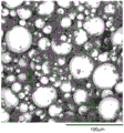
Fig. 4-10 are Scanning Electron Microscope (SEM) micrographs of cross sections of exemplary polymer matrix composites described herein (examples 1,2,3, 4, 5, 8, and 10, respectively).
Fig. 11-13 are Scanning Electron Microscope (SEM) micrographs of cross-sections of exemplary polymer matrix composites described herein (examples 12, 13, and 14, respectively).
Fig. 14, 16, and 18 show Scanning Electron Microscope (SEM) micrographs of cross-sections of exemplary polymer matrix composites described herein (examples 15, 16, and 17, respectively).
Fig. 15A, 17A, and 19A show digital optical camera photographs of a top view of exemplary unexpanded polymer matrix composites described herein (examples 15, 16, and 17, respectively).
Fig. 15B, 17B, and 19B show digital optical camera photographs of a top view of exemplary expanded polymer matrix composites described herein (examples 15, 16, and 17, respectively).
Fig. 20A and 20B show Scanning Electron Microscope (SEM) micrographs of a cross-section of an exemplary polymer matrix composite (example 18) described herein.
Fig. 21A and 21B show Scanning Electron Microscope (SEM) micrographs of a cross section of an exemplary polymer matrix composite (example 19) described herein.
Fig. 22 shows a Scanning Electron Microscope (SEM) micrograph of a cross-section of an exemplary polymer matrix composite (example 20) described herein.
Fig. 23 shows a Scanning Electron Microscope (SEM) micrograph of a cross-section of an exemplary polymer matrix composite (example 21) described herein.
Fig. 24 is a schematic drawing showing a Scanning Electron Microscope (SEM) micrograph of a cross-section of an exemplary polymer matrix composite (example 22) described herein.
Fig. 25 is a schematic drawing showing a Scanning Electron Microscope (SEM) micrograph of a cross-section of an exemplary polymer matrix composite (example 34) described herein.
Fig. 26 is a schematic drawing showing a Scanning Electron Microscope (SEM) micrograph of a cross-section of an exemplary polymer matrix composite (example 35) described herein.
Fig. 27 and 28 show Scanning Electron Microscope (SEM) micrographs of cross-sections of exemplary polymer matrix composites described herein (examples 38 and 39, respectively).
Fig. 29, 30A, 30B, 32, and 33 show Scanning Electron Microscope (SEM) micrographs of cross-sections of exemplary polymer matrix composites described herein (examples 42, 43, 44, and 45, respectively).
Figure 31 shows a digital image of water absorption after placing a disc of the polymer matrix composite (example 43) described herein in 100m L water.
Fig. 34-37 show Scanning Electron Microscope (SEM) micrographs of cross-sections of exemplary polymer matrix composites described herein (examples 46, 47, 48, and 49, respectively).
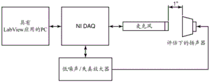
Fig. 38 is a schematic illustration of a test configuration for determining sound pressure level (SP L) for a polymer matrix composite comprising acoustically active particles described herein.
Fig. 39 is a schematic drawing of a Scanning Electron Microscope (SEM) micrograph showing a cross-section of an exemplary polymer matrix composite (example 50) described herein.
Fig. 40 is a schematic drawing showing a Scanning Electron Microscope (SEM) micrograph of a cross-section of an exemplary polymer matrix composite (example 53) described herein.
Detailed Description
The present disclosure describes a method of making a polymer matrix composite comprising a porous polymer network structure; and a plurality of particles distributed within the polymer network structure, the method comprising:
combining (e.g., mixing or blending) a thermoplastic polymer, a solvent, and a plurality of particles to provide a slurry;
shaping the slurry into an article (e.g., a layer);
heating the article in an environment to retain in the article at least 90% (in some embodiments, at least 91%, 92%, 93%, 94%, 95%, 96%, 97%, 98%, 99%, or even at least 99.5%) by weight of the solvent based on the weight of the solvent in the article, and to dissolve at least 50% (in some embodiments, at least 55%, 60%, 65%, 70%, 75%, 80%, 85%, 90%, 95%, 96%, 97%, 98%, 99%, or even 100%) by weight of the thermoplastic polymer based on the total weight of the thermoplastic polymer; and
inducing phase separation of the thermoplastic polymer from the solvent to provide the polymer matrix composite.
In some embodiments, the polymer network structure may comprise, consist essentially of, or consist of at least one thermoplastic polymer. Exemplary thermoplastic polymers include polyurethanes, polyesters (e.g., polyethylene terephthalate, polybutylene terephthalate, and polylactic acid), polyamides (e.g., nylon 6, and polypeptides), polyethers (e.g., polyethylene oxide and polypropylene oxide), polycarbonates (e.g., bisphenol a polycarbonate), polyimides, polysulfones, polyethersulfones, polyphenylene ethers, polyacrylates (e.g., thermoplastic polymers formed by the addition polymerization of one or more monomers comprising acrylate functionality), polymethacrylates (e.g., thermoplastic polymers formed by the addition polymerization of one or more monomers comprising methacrylate functionality), polyolefins (e.g., polyethylene and polypropylene), styrene and styrene-based random and block copolymers, chlorinated polymers (e.g., polyvinyl chloride), fluoropolymers (e.g., polyvinylidene fluoride; tetrafluoroethylene, poly (lactic acid)), poly (lactic acid), poly (ethylene oxide), poly, Copolymers of hexafluoropropylene and vinylidene fluoride; copolymers of ethylene and tetrafluoroethylene; hexafluoropropylene; and polytetrafluoroethylene), and copolymers of ethylene and chlorotrifluoroethylene. In some embodiments, the thermoplastic polymer comprises a homopolymer or a copolymer (e.g., a block copolymer or a random copolymer). In some embodiments, the thermoplastic polymer comprises a mixture of at least two thermoplastic polymer types (e.g., a mixture of polyethylene and polypropylene or a mixture of polyethylene and polyacrylate). In some embodiments, the polymer can be at least one of polyethylene (e.g., ultra-high molecular weight polyethylene), polypropylene (e.g., ultra-high molecular weight polypropylene), polylactic acid, poly (ethylene-co-chlorotrifluoroethylene), and polyvinylidene fluoride. In some embodiments, the thermoplastic polymer is a single thermoplastic polymer (i.e., it is not a mixture of at least two thermoplastic polymer types). In some embodiments, the thermoplastic polymer consists essentially of polyethylene (e.g., ultra-high molecular weight polyethylene) or consists of polyethylene.
In some embodiments, the thermoplastic polymer used to prepare the polymer matrix composites described herein is a particle having a particle size of less than 1000 microns (in some embodiments, in the range of 1 micron to 10 microns, 10 microns to 30 microns, 30 microns to 100 microns, 100 microns to 200 microns, 200 microns to 500 microns, 500 microns to 1000 microns).
In some embodiments, the porous polymer network structure comprises at least one of: polyacrylonitrile, polyurethanes, polyesters, polyamides, polyethers, polycarbonates, polyimides, polysulfones, polyphenylene ethers, polyacrylates, polymethacrylates, polyolefins, styrene or styrene-based random and block copolymers, chlorinated polymers, fluorinated polymers or copolymers of ethylene and chlorotrifluoroethylene. In some embodiments, the porous polymer network structure comprises a number averageThe molecular weight is 5 × 10⁴g/mol to 1 × 10⁷Polymers in the g/mol range (in some embodiments, number average molecular weight of 1 × 10⁶g/mol to 8 × 10⁶g/mol、2×106g/mol to 6 × 10⁶g/mol, or even 3 × 10⁶g/mol to 5 × 10⁶In the range of g/mol). For the purposes of this disclosure, the number average molecular weight can be measured by techniques known in the art (e.g., Gel Permeation Chromatography (GPC)). GPC can be performed in a suitable solvent for the thermoplastic polymer, along with the use of narrow molecular weight distribution polymer standards (e.g., narrow molecular weight distribution polystyrene standards). Thermoplastic polymers are generally characterized as being partially crystalline, exhibiting a melting point. In some embodiments, the melting point of the thermoplastic polymer may be in the range of 120 ℃ to 350 ℃ (in some embodiments, in the range of 120 ℃ to 300 ℃,120 ℃ to 250 ℃, or even 120 ℃ to 200 ℃). The melting point of the thermoplastic polymer can be measured by techniques known in the art (e.g., the onset temperature as measured in a Differential Scanning Calorimetry (DSC) test performed with a 5mg to 10mg sample at a heating scan rate of 10 ℃/min while the sample is under a nitrogen atmosphere).
In some embodiments, the polymer network structure is a continuous network structure (i.e., the polymer phase includes a structure that is open-celled with continuous voids or pores that form interconnections between voids and extend throughout the structure). In some embodiments, at least 2% (in some embodiments, at least 5%, 10%, 20%, 30%, 40%, 50%, 60%, 70%, 80%, 90%, 95%, or even 100%) by volume of the polymer network structure may be a continuous polymer network structure. It should be noted that for the purposes of this disclosure, the volume fraction of the polymer matrix composite comprised of particles is not considered to be part of the polymer network structure. In some embodiments, the polymer network extends between two particles, thereby forming a network of interconnected particles.
The solvent (e.g., the first solvent) is selected such that it forms a miscible polymer-solvent solution. The solvent may be a blend of at least two separate solvents. In some embodiments, when the polymer is a polyolefin (C: (A))E.g., at least one of polyethylene and polypropylene), the solvent may be, e.g., at least one of: mineral oil, tetralin, decalin, o-dichlorobenzene, cyclohexane toluene mixtures, dodecane, paraffin oil/wax, kerosene, isoparaffinic fluids, o-xylene/cyclohexane mixtures (1/1wt/wt), camphene, 1,2,4 trichlorobenzene, octane, orange oil, vegetable oil, castor oil or palm kernel oil. In some embodiments, when the polymer is polyvinylidene fluoride, the solvent may be, for example, at least one of ethylene carbonate, propylene carbonate, or 1,2, 3-triacetoxypropane. The solvent may be removed, for example by evaporation. High vapor pressure solvents are particularly suitable for this removal process. However, if the first solvent has a low vapor pressure, it may be desirable for the second solvent, which has a higher vapor pressure, to extract the first solvent, followed by evaporation of the second solvent. For example, in some embodiments, when mineral oil is used as the first solvent, isopropanol or methyl nonafluorobutyl ether (C) at elevated temperature (e.g., about 60 ℃) is used4F9OCH3) Ethyl nonafluorobutyl ether (C)4F9OC2H5) And trans-1, 2-dichloroethylene (e.g., available under the trade designation NOVEC 72DE from 3M company, st. paul, MN, st.) of st paul, MN can be used as the second solvent to extract the first solvent, followed by evaporation of the second solvent. In some embodiments, when at least one of vegetable oil or palm kernel oil is used as the first solvent, isopropanol at elevated temperatures (e.g., about 60 ℃) may be used as the second solvent. In some embodiments, when ethylene carbonate is used as the first solvent, water may be used as the second solvent.
These additives include viscosity modifiers (e.g., fumed silica, block copolymers, and waxes), plasticizers, heat stabilizers (e.g., such as, for example, BASF, <ttransfer = L ">ttl <t/t >ttudwigshafen, Germany) available from BASF of lade winhich, Germany under the trade name" Irganox 1010 "), antimicrobial agents (e.g., silver and quaternary ammonium), flame retardants, antioxidants, dyes, pigments, and Ultraviolet (UV) stabilizers.
The slurry is typically continuously mixed or blended to prevent or reduce settling or separation of the polymer and/or particles from the solvent. In some embodiments, the slurry is degassed to remove residual air using techniques known in the art.
The slurry can be formed into an article using techniques known in the art, including knife coating, roll coating (e.g., roll coating through a defined nip), and coating through any number of different dies of suitable size or profile.
In some embodiments of the methods described herein, the combining is performed at a temperature below the melting point of the polymer and below the boiling point of the solvent.
In some embodiments of the methods described herein, the heating is performed at least one temperature above the melting point of the miscible thermoplastic polymer-solvent solution and below the boiling point of the solvent.
In some embodiments of the methods described herein, inducing phase separation is performed at least one temperature below the melting point of the polymer in the slurry. While not wanting to be bound, it is believed that in some embodiments, the solvent used to prepare the miscible blend with the polymer may cause a decrease in the melting point in the polymer. The melting point as described herein includes any melting point depression below the polymer solvent system.
In some embodiments of the methods described herein, the polymer network structure may be formed during phase separation. In some embodiments, the polymer network structure may be provided by induced phase separation of miscible thermoplastic polymer-solvent solutions. In some embodiments, phase separation is thermally induced (e.g., via Thermally Induced Phase Separation (TIPS) quenching to a temperature lower than the temperature used during heating). Cooling may be provided, for example, in air, liquid, or on a solid interface, and may be varied to control phase separation. The polymer network structure may be inherently porous (i.e., have pores). The pore structure may be open, enabling fluid communication from an interior region of the polymer network structure to an exterior surface of the polymer network structure and/or between a first surface of the polymer network structure and an opposing second surface of the polymer network structure.
In some embodiments of the methods described herein, the weight ratio of solvent to polymer is at least 9: 1. In some embodiments, the volume ratio of particles to polymer is at least 9: 1. In some embodiments, for ease of manufacturing, it may be desirable to form the layer at room temperature. Generally, during formation using phase separated layers, the relatively small pores are particularly prone to collapse during solvent extraction. The relatively high particle and polymer loading achievable by the methods described herein can reduce pore collapse and produce a more uniform defect-free polymer matrix composite.
In some embodiments of the polymer matrix composites prepared as described herein, the particles are present in a range of from 1 to 99 weight percent (in some embodiments, in a range of from 15 to 99 weight percent, 25 to 98 weight percent, 50 to 98 weight percent, 75 to 98 weight percent, or even 93 to 97 weight percent) based on the total weight of the polymer matrix composite (excluding any solvent), and may depend, for example, on the particular particles used.
The polymer network structure may be described as a porous polymer network or a porous phase separated polymer network. Generally, the porous polymer network (so prepared) comprises an interconnected porous polymer network structure comprising a plurality of interconnected morphologies (e.g., at least one of fibrils, nodes, open cells, closed cells, lobed laces, strands, nodes, spheres, or honeycomb structures). The interconnected polymeric structures may adhere directly to the surface of the particles and act as a binder for the particles. In this regard, the spaces between adjacent particles (e.g., particles or agglomerate particles) may comprise a polymeric structure rather than a solid matrix material, thereby providing the desired porosity.
In some embodiments, the polymer network structure may comprise a three-dimensional network structure comprising an interconnected network of polymeric fibrils. In some embodiments, the average width of the individual fibrils is in the range of 10nm to 100nm (in some embodiments, in the range of 100nm to 500nm, or even in the range of 500nm to 5 microns).
In some embodiments, the particles are dispersed within the polymer network structure such that the outer surface of individual units of the particles (e.g., individual particles or individual agglomerate particles) are largely free from contact with the polymer network structure or are uncoated. In this regard, in some embodiments, the average area coverage percentage of the polymeric network structures on the outer surface of an individual particle (i.e., the percentage of the area of the outer surface in direct contact with the polymeric network structures) is no greater than 50% (in some embodiments, no greater than 40%, 30%, 25%, 20%, 10%, 5%, or even no greater than 1%) based on the total surface area of the outer surface of the individual particle.
In some embodiments, the polymer network structure is impermeable to internal pores or the internal surface area of individual particles (e.g., individual particles or individual agglomerate particles) is largely free from contact with the polymer network structure or is uncoated.
Exemplary particles include acoustically active particles, soft magnetic particles, thermally conductive particles, thermally insulating particles, intumescent particles, functional particles, dielectric particles, indicator particles, polar solvent soluble particles, polar solvent swellable particles, or heat absorbing particles.
Acoustically active particles
As used herein, "acoustically active particles" refers to the ability of a material to interact with a time-varying pressure wave (e.g., sound wave) impinging thereon or propagating therethrough to cause a change in a wave characteristic (e.g., frequency, wavelength, amplitude, velocity), which is manifested as a change in the resonant frequency and/or sound pressure level output of a sound generating device (e.g., a speaker) containing the material3Resonant frequency (F) of a loudspeaker system of the rear volume0) ReduceAt least 10Hz, or will have a length of 1cm3The sound pressure level (SP L) of the rear volume loudspeaker system is improved by at least 0.1 dB.
In some embodiments, the acoustically active particles are present in the polymer matrix composite in a range of 50 wt.% to 99 wt.% (in some embodiments, in a range of 70 wt.% to 98 wt.%, 80 wt.% to 95 wt.%, or even 94 wt.% to 98 wt.%) based on the total weight of the acoustically active particles and the polymer (excluding any solvent).
Exemplary acoustically active particles include molecular sieves, fullerenes and carbon nanotubes, and include metal oxides (e.g., silicon dioxide (SiO)2) Alumina (Al)2O3) Zirconium oxide (ZrO)3) Magnesium oxide (MgO) and black iron oxide (Fe)3O4) Particles of (d). In some embodiments, the acoustically active material can have a composition that is free or substantially free of zeolite and activated carbon.
In some embodiments, the acoustically active material can have an internal porosity. As used herein, "internal porosity" may refer to one or more continuous or discontinuous void volumes within the acoustically active material particles or agglomerates of acoustically active material. The one or more void volumes may intersect the surface of the acoustically active material particles or agglomerates of acoustically active material particles, or may be contained entirely within the acoustically active material particles or agglomerates of acoustically active material particles. The one or more void volumes may be filled with air or another gas or mixture of gases at atmospheric, subatmospheric, or superatmospheric pressure. In some embodiments, the acoustically active material can have an average pore size in a range between 1nm and 100 microns. In some embodiments, the pore size of the active material may have a bimodal distribution, with small pores in the range of 1 nanometer to 100 nanometers and large interparticle pores in the range of 100 nanometers to 100 microns. Conventional aperture analysis techniques (including imaging of cross-sections (e.g. optical, scanning electron or atomic force microscopy) and the use of appropriate software, such as ImageJ software (open source software, as available, for example, on http:// ImageJ. net)Obtained online)) analysis images) can be used for statistical analysis of pore size and pore size distribution. X-ray microtomography and mercury porosimetry may also be used to analyze pore size and/or pore size distribution. In some embodiments, the acoustically active material can have a thickness of greater than 50m2(in some embodiments, greater than 500 m)2(ii)/g; in some embodiments, at 50m2G to 1000m2/g、300m2G to 1000m2/g、500m2G to 1000m2G or even 300m2G to 500m2In the range of/g). Conventional specific surface area analysis techniques, including Brunauer-Emmett-Teller (BET) surface area or oil absorption, may be used for statistical analysis of specific surface area.
In some embodiments, the acoustically active material is hydrophobic. The material may be surface treated or modified to impart hydrophobicity to other hydrophilic materials. In some embodiments, the surface treatment agent comprises a silane or fluorine-based surface treatment agent. In some embodiments, the hydrophobic surface treatment is applied at a concentration that minimizes the consumption of active surface sites while still imparting hydrophobicity. In some embodiments, the total number of active surface sites is calculated based on the theoretical distribution of the surface sites and the measured surface area or by a method such as O2The total number of active surface sites, as measured by chemisorption, alcohol absorption, or similar techniques known to those skilled in the art, attaches the hydrophobic surface treatment agent to active surface sites in the range of 0.1% to 10% (in some embodiments, in the range of 0.1% to 5%, 0.1% to 3%, or even 0.5% to 3%). As used herein, the term "active surface site" refers to a chemical site on the surface of the acoustically active material that is available for ionic or covalent bonding to a modifying chemical species (e.g., isolated oxygen atoms).
In some embodiments, the acoustically active material can be electrically insulating (i.e., having at least 1 × 10)10Resistivity of Ω · m).
In some embodiments, the acoustically active particles have an average particle size (average length of longest dimension) in the range of 100nm to 20 microns (in some embodiments, in the range of 500nm to 10 microns, 100nm to 2 microns, 500nm to 2 microns, 1 micron to 10 microns, or even 1 micron to 5 microns). In some embodiments, the acoustically active material may be in the form of agglomerate particles composed of a plurality of smaller particles bonded together, for example, by cohesion, an inorganic binder, or an organic binder.
The polymer matrix composite comprising acoustically active particles can be used, for example, in electronic devices (e.g., mobile phones, tablets, and laptops) as part of an acoustic device (e.g., a speaker or microphone). Embodiments of the polymer matrix composite can reduce the resonant frequency of the cavity when the resonant frequency is in a range of, for example, about 50Hz to about 1500 Hz. In some embodiments, the polymer matrix composite may be present in the cavity, for example, in the form of a film or mat that may be electrically insulating and hydrophobic. The polymer matrix composites may also be used as acoustically active materials in, for example, medical devices, automotive devices, and communication devices such as headphones and audio-visual devices. For more details, see, e.g., provisional application with U.S. serial No. 62/519,560 filed on 2017, 6, 14, the disclosure of which is incorporated herein by reference.
Soft ferromagnetic particles
As used herein, "soft ferromagnetic particles" refers to magnetic field-oriented materials. The term "soft" describing ferromagnetic particulate materials has its conventional meaning in the art and relates to the ability of a non-magnetic material to become magnetic when placed within a magnetic field (e.g., a weak magnetic field). When the magnetic field is removed, the induced magnetism of the soft ferromagnetic particulate material will substantially disappear (i.e. the material exhibits reversible magnetism in the applied magnetic field). In some embodiments, the coercivity Hc of the soft magnetic particulate material is no greater than 1000A/m (in some embodiments, in the range of 1A/m to 1000A/m (in some embodiments, in the range of 10A/m to 1000A/m or even 30A/m to 1000A/m)). The soft ferromagnetic material can have a narrow hysteresis loop (i.e., a low coercivity value as described above, along with a high magnetic saturation induction in excess of 300mT (in some embodiments, 500mT or even 1.0T), greater than 100 μ0High magnetic permeability (in some embodiments, greater than 1000 μ)0Or even 10,000 mu0) In which μ0Permeability to vacuum, 4 pi × 10-7H/m and has a sufficiently low conductivity so that the applied field penetrates acceptably into the soft ferromagnetic particles at the operating frequency. This maximum allowable level of conductivity depends on the superficial depth of radiation in the particles, which in most cases should be less than about twice the thickness of the soft ferromagnetic particles. The skin depth in meters can be calculated from the following formula (all using MKS units, and where □ equals the electrical conductivity of the sheet (in siemens/meter))

In some embodiments, the soft ferromagnetic particles are present in the polymer matrix composite in a range of from 50 to 99 weight percent (in some embodiments, in a range of from 70 to 98 weight percent, 80 to 95 weight percent, or even 94 to 98 weight percent) based on the total weight of the soft ferromagnetic particles and the polymer (excluding any solvent).
In some embodiments, the soft ferromagnetic particulate material comprises at least one of iron, an Fe-Cr alloy, an Fe-Si alloy (e.g., Fe-Si-Al (e.g., available under the Trade designation "SENDUST" from Tianjin Acoket Trade, Inc., of Tianjin, China, Tianjin Ecotecech Trade, L td., Tianjin, China)), and Fe-Si-Cr), FeCoFeCoB, an iron-based amorphous alloy, a nanocrystalline iron-based oxide, a nanocrystalline iron-based nitride, a nickel-based alloy (e.g., Ni-Fe alloy and Ni-Si alloy), CoNbZr, or a boron-based amorphous alloy.
In some embodiments, the soft ferromagnetic particulate material is in the shape of a sheet. A lamina can be considered an irregularly shaped plate-like structure having first and second major surfaces and a thickness substantially perpendicular to at least one of the first and second major surfaces. In some embodiments, the soft ferromagnetic particulate material is a soft ferromagnetic particulate sheet material, wherein each sheet has a first major surface and a maximum thickness T perpendicular to the first major surface of the sheet. In some embodiments, the soft ironThe magnetic particle sheet material may pass through a median diameter D50(which relates to a length dimension of L) and a maximum thickness T in some embodiments, the soft ferromagnetic particulate material may be an anisotropic soft ferromagnetic particulate material50Divided by the maximum thickness of the anisotropic particles as determined, for example, by image analysis. The value of the maximum thickness can be considered as the median value T for a particular set of soft ferromagnetic particle materialsm. Ratio D50:TmIs the median aspect ratio. In some embodiments, the median aspect ratio D50:TmIn the range of 5:1 to 1000:1 (in some embodiments in the range of 10:1 to 1000:1, 20:1 to 1000:1, 5:1 to 500:1, 10:1 to 500:1, 20:1 to 500:1, 5:1 to 200:1, 10:1 to 200:1, or even 20:1 to 200: 1).
In some embodiments, the image length L i of the flake as viewed and measured in the cross-sectional image of the polymer composite can be considered the length of the flake and the image thickness Ti of the flake can be considered the maximum thickness of the flake as viewed and measured in the cross-sectional image of the polymer composite the image can be, for example, an optical or Scanning Electron Micrograph (SEM). for a particular set of soft ferromagnetic particle flakes, the values of L i and Ti can be considered as the average of the subset of flakes L ia (average image length) and Tia (average image thickness). in some embodiments, L ia/Tia is in the range of 5:1 to 1000:1, 10:1 to 1000:1, 20:1 to 1000:1, 5:1 to 500:1, 10:1 to 500:1, 20:1 to 500:1, 5:1 to 200:1, 10:1 to 200:1, or even 20:1 to 200:1, using standard statistical analysis methods.
In some embodiments, D50In the range of 5 microns to 5000 microns (in some embodiments, in the range of 5 microns to 1000 microns, 5 microns to 500 microns, 5 microns to 200 microns, 10 microns to 5000 microns, 10 microns to 1000 microns, 10 microns to 500 microns, 10 microns to 200 microns, 25 microns to 5000 microns, 25 microns to 1000 microns, 25 microns to 500 microns, or even 25 microns to 200 microns).
In some embodiments of the present invention, the substrate is,the flakes of soft ferromagnetic particle flake material have a median diameter D50And the thermoplastic polymer network structure has an average pore diameter P, and D50>2P. In some embodiments, D50In the range of 25 to 5000 microns, P is between 50 nanometers to 25 microns, and D50>2P (in some embodiments, D)50In the range of 10 micrometers to 5000 micrometers, P in the range of 50 nanometers to 25 micrometers, and D50>2P;D50In the range of 25 micrometers to 5000 micrometers, P in the range of 50 nanometers to 25 micrometers, and D50>4P;D50In the range of 10 micrometers to 5000 micrometers, P in the range of 50 nanometers to 25 micrometers, and D50>4P;D50In the range of 25 micrometers to 5000 micrometers, P in the range of 50 nanometers to 25 micrometers, and D50>6P, or even D50In the range of 10 micrometers to 5000 micrometers, P in the range of 50 nanometers to 25 micrometers, and D50>6P)。
The polymer matrix composite material comprising soft magnetic particles may be used, for example, in wireless power modification applications or any other electronic applications where it is desirable to direct or maintain a magnetic field away from sensitive electronic components and batteries. For more details, see, e.g., application with U.S. serial No. 15/382,834 filed on 12/19/2016 and U.S. patent publication 2018/0174723 published on 21/6/2018, the disclosures of which are incorporated herein by reference.
-thermally conductive particles
As used herein, "thermally conductive particles" refers to particles having a thermal conductivity greater than 2W/(m × K). In some embodiments, the thermally conductive particles are present in the polymer matrix composite in a range from 15 to 99 weight percent (in some embodiments, in a range from 25 to 98 weight percent, 50 to 98 weight percent, 75 to 98 weight percent, or even 93 to 97 weight percent) based on the weight of the thermally conductive particles and the polymer (excluding any solvent).
Exemplary thermally conductive particles include metals, semiconductors, and ceramics. Exemplary thermally conductive particles include at least one of: aluminum, copperSilver, graphite, diamond, SiC, Si3N4、AlN、BeO、MgO、Al2O3Aluminum hydroxide, aluminum oxyhydroxide, hexagonal boron nitride (h-BN), cubic boron nitride (c-BN), ZnO, natural aluminosilicate, or synthetic aluminosilicate.
Exemplary sizes of the thermally conductive particles range from hundreds of nanometers to hundreds of micrometers in size. Exemplary shapes of thermally conductive particles include irregular, plate-like, needle-like, spherical shapes, and agglomerated forms. The size of the agglomerates may range, for example, from a few microns up to and including a few millimeters. The particles may be mixed to have a multimodal size distribution, which may for example allow for an optimal bulk density.
In some embodiments, the thermally conductive particles comprise electrically non-conductive particles (e.g., ceramic particles comprising boron nitride, aluminum trihydrate, silicon carbide, and metal oxides (e.g., aluminum oxide and iron oxide)).
In some embodiments, the thermally conductive particles comprise electrically conductive particles (e.g., metal particles comprising aluminum, copper, nickel, and gold).
In some embodiments, the thermally conductive particles have an average particle size (average length of longest dimension) in the range of 100nm to 2mm (in some embodiments, in the range of 200nm to 1000 nm).
In some embodiments, the thermally conductive particles have a bimodal or trimodal distribution. Multimodal distribution of particles may allow for higher packing efficiency, improved particle-to-particle contact, and thus improved thermal conductivity.
The polymer matrix composite comprising thermally conductive particles so prepared (i.e., prior to any compaction or other post-forming densification) typically has at least 0.3g/cm3(in some embodiments, at least 0.4g/cm3、0.5g/cm3、1g/cm3、2g/cm3、3g/cm3Or even at least 4g/cm3(ii) a In some embodiments, at 0.3g/cm3To 7g/cm3、1g/cm3To 6g/cm3、2g/cm3To 5g/cm3Or even 3g/cm3To 4g/cm3In range).
In some embodiments, the thermal conductivity of the polymer matrix composite comprising thermally conductive particles is improved by compressing the polymer matrix composite thereby increasing the density of the polymer matrix composite. In some embodiments, the compression may be performed at an elevated temperature (e.g., above the glass transition temperature of the polymer matrix, or even in some embodiments, above the melting point of the polymer matrix). In some embodiments, the compressed polymer matrix composite has at least 1g/cm3(in some embodiments, at least 2g/cm3、3g/cm3、4g/cm3、5g/cm3、6g/cm3、7g/cm3、8g/cm3、9g/cm3Or even at least 10g/cm3(ii) a In some embodiments, at 1g/cm3To 10g/cm3、1g/cm3To 9g/cm3、3g/cm3To 8g/cm3Or even 4g/cm3To 7g/cm3In range).
In some embodiments, the thermal conductivity of the polymer matrix composite is improved by compressing the polymer matrix composite thereby increasing the density of the polymer matrix composite. In some embodiments, the compression may be performed at an elevated temperature (e.g., above the glass transition temperature of the polymer matrix, or even in some embodiments, above the melting point of the polymer matrix). In some embodiments, the compressed polymer matrix composite has at least 1g/cm3 (in some embodiments, at least 2 g/cm)3、3g/cm3、4g/cm3、5g/cm3、6g/cm3、7g/cm3、8g/cm3、9g/cm3Or even at least 10g/cm3(ii) a In some embodiments, at 1g/cm3To 10g/cm3、1g/cm3To 9g/cm3、3g/cm3To 8g/cm3Or even 4g/cm3To 7g/cm3In range).
In some embodiments, the polymer matrix composite comprising thermally conductive particles has a porosity of less than 80% (in some embodiments, in the range of 0% to 80%, 0% to 70%, 0% to 60%, 10% to 80%, 10% to 70%, 10% to 60%, 10% to 50%, 10% to 40%, 10% to 30%, or even 5% to 20%).
In some embodiments, the polymer matrix composite comprising thermally conductive particles is in the form of a layer having a thickness in the range of 50 microns to 7000 microns, wherein the thickness does not include the height of any protrusions extending from the base of the layer.
In some embodiments, after compression, the compressed polymer matrix composite has a density of at least 1g/cm3(in some embodiments, at least 2g/cm3、3g/cm3、4g/cm3、5g/cm3、6g/cm3、7g/cm3、8g/cm3、9g/cm3Or even at least 10g/cm3(ii) a In some embodiments, at 1g/cm3To 10g/cm3、1g/cm3To 9g/cm3、3g/cm3To 8g/cm3Or even 4g/cm3To 7g/cm3Within the range of (a).
In some embodiments, the polymer matrix composite comprising thermally conductive particles is compressed to increase its density and thermal conductivity by increasing particle-to-particle contact if electrically conductive particles such as copper are used, the increased particle-to-particle contact can be measured by decreasing electrical resistance as a function of increasing compression in some embodiments, the electrical resistance of the uncompressed polymer matrix composite is in the range of 14 megaohms to at least 100 megaohms in some embodiments, the electrical resistance of the compressed polymer matrix composite is in the range of 0.5 ohms to 13,000 ohms in some embodiments, compressing the polymer matrix composite decreases its electrical resistance (in some embodiments, at least 8 × 10 ohms)9% (in some embodiments, 2.5 × 10⁹%))。
Compression increases the density, which inherently reduces the insulating air volume (or porosity) of the polymer matrix composite containing the thermally conductive particles, and thus will increase thermal conductivity. Also, increased particle-to-particle contact with thermally conductive particles can be measured by increased thermal conductivity.
In some embodiments, the uncompressed polymer matrix comprising thermally conductive particles has a through plane thermal conductivity in the range of 0.2W/(m × K) to 0.8W/(m × K), and an in plane thermal conductivity in the range of 0.73W/(m × K) to 2.5W/(m × K). In some embodiments, the through plane thermal conductivity of the compressed polymer matrix composite is in the range of 0.4W/(m × K) to 11.4W/(m × K); the in-plane thermal conductivity is in the range of 0.87W/(mK) to 74W/(mK).
In some embodiments, compressing the polymer matrix composite comprising thermally conductive particles increases its thermal conductivity by at least 25% (in some embodiments, at least 100%, 1000%, 2000%, 3000%, or even at least 3500%) in the through plane, and by at least 84% (in some embodiments, at least 1000%, 2000%, 3000%, 4000%, 5000%, or even at least 5400%) in the plane.
Polymer matrix composites comprising thermally conductive particles can be used, for example, as thermal interface materials (e.g., thermal conductors in electronic devices such as batteries, motors, refrigerators, circuit boards, solar cells, and heaters)). For more details on the polymer matrix composites comprising thermally conductive particles prepared by the methods described herein, see also co-pending application having U.S. provisional patent application 62/587031 (filed 11/16/2017), the disclosure of which is incorporated herein by reference.
-thermally insulating particles
As used herein, "thermally insulating particles" refers to particles having a thermal conductivity of no greater than 0.1W/(m × K). In some embodiments, the insulating particles are present in the polymer matrix composite in a range from 15 wt% to 99 wt% (in some embodiments, in a range from 5 wt% to 98 wt%, 50 wt% to 98 wt%, 75 wt% to 98 wt%, or even 84 wt% to 91 wt%), based on the total weight of the insulating particles and the polymer (excluding any solvent).
Exemplary insulating particles include ceramics (including glass, crystalline ceramics, and glass ceramics), polymers, and metals. Exemplary insulating particles include at least one of a ceramic (e.g., glass bubbles), vermiculite, perlite, diatomaceous earth, aerogel, or polymer.
Exemplary sizes of the insulating particles range from hundreds of nanometers to thousands of micrometers in size. Exemplary shapes of the insulating particles include irregular, plate-like, needle-like, spherical shapes, and agglomerated forms. The size of the agglomerates may range, for example, from a few microns up to and including a few millimeters. In some embodiments, the insulating particles are in the form of hollow, bubble, or porous materials to trap more air, thereby providing better thermal insulation.
In some embodiments, the insulating particles have an average particle size (average length of longest dimension) in the range of 100nm to 2mm (in some embodiments, in the range of 15 microns to 125 microns or even 30 microns to 60 microns).
In some embodiments, the polymer matrix composite comprising the insulating particles has a porosity of at least 25% (in some embodiments, in the range of 25% to 50%, 30% to 60%, or even 40% to 90%).
In some embodiments, the polymer matrix composite comprising thermally insulating particles is in the form of a layer having a thickness in the range of 50 microns to 7000 microns, wherein the thickness does not include the height of any protrusions extending from the base of the layer.
The polymer matrix composites comprising the insulating particles can be used, for example, in jacketing, refrigeration, and pipe coatings. For more details on the polymer matrix composites comprising thermally insulating particles prepared by the methods described herein, see also co-pending application having U.S. provisional patent application 62/587035 (filed 11/16/2017), the disclosure of which is incorporated herein by reference.
-particles of expanded material
As used herein, "expanded material particles" refers to particles that swell when exposed to heat. The result of the exposure to heat is an increase in particle volume and a decrease in particle density. The variation in particle volume and density can be tested according to ASTM standard E2786(2015), the disclosure of which is incorporated herein by reference.
In some embodiments, the intumescent material particles are present in the polymer matrix composite in a range from 15 to 99 weight percent (in some embodiments, in a range from 25 to 98 weight percent, 50 to 98 weight percent, 75 to 98 weight percent, or even 93 to 97 weight percent) based on the total weight of the intumescent material particles and polymer (excluding any solvent).
The expanded material particles may be in the form of at least one of a polymeric material or an inorganic material capable of significantly increasing in volume as a result of exposure to heat above its activation temperature. Exemplary intumescent material particles include at least one of sodium silicate, intercalated graphite, aluminum hydroxide, magnesium hydroxide, ammonium polyphosphate, clay, or vermiculite.
The selection of the expanded material particles may vary depending on, for example, the desired end use. For example, for temperatures of about 500 ℃, unexpanded vermiculite materials are desirable because they typically begin to expand at temperatures in the range of about 300 ℃ to about 340 ℃ to fill the expansion gap between, for example, an expanded metal housing and a monolith in a catalytic converter. For use below about 500 ℃ (e.g., use in diesel monoliths or particulate filters), expandable graphite or mixtures of expandable graphite with unexpanded vermiculite material may be desirable because expandable graphite typically begins to expand or swell at about 210 ℃. Treated vermiculite is also useful and typically expands at a temperature of about 290 ℃.
Useful intumescent materials also include unexpanded vermiculite ore, treated unexpanded vermiculite ore, partially dehydrated vermiculite ore, expandable graphite (e.g., expandable graphite flakes available under the trade designation "GRAFOI L GRADE 338-5O" from UCAR Carbon co ltd, inc., Cleveland, OH), mixtures of expandable graphite with treated and/or untreated unexpanded vermiculite ore, treated expandable sodium silicate (e.g., insoluble sodium silicate available under the trade designation "EXPANTRO L" from 3M Company, st. paul, MN) of saint paul, minnesota), and mixtures thereof.
The treated unexpanded vermiculite flakes or ore includes unexpanded vermiculite treated by methods such as by ion exchange with ion exchange salts (e.g., ammonium dihydrogen phosphate, ammonium nitrate, ammonium chloride, potassium chloride, and other suitable compounds as are known in the art).
The amount and type of intumescent material incorporated into the polymer matrix composite can significantly increase the cost of the product. Untreated intumescent materials, such as unexpanded vermiculite, are generally less expensive than treated intumescent materials, but may provide different expansion temperatures as well as amounts and rates of expansion.
In some embodiments, the expanded material particles have a layered structure that allows for easy exfoliation. Within each layer of particles, a fluid (e.g., sulfuric acid) may be introduced and held tightly to the surface of the layer (embedded in the layer). When such materials are exposed to heat, the fluid held within the layer expands. The expansion of the fluid pushes against the layers, further separating them (spalling). The observed result of this behavior is bulk membrane volume expansion. The degree of expansion and the temperature at which expansion occurs depend, for example, on the type of fluid embedded in the layer.
In some embodiments, the expanded material is a particle that is predominantly in a solid phase that is converted to include both a solid phase and a gas phase. For example, the intumescent material particles may contain surface adsorbed species that volatilize when heated. Examples of such particles include those associated with water (e.g., calcium sulfate dehydrate). When this type of material is heated, some of the water molecules associated with the surface of the particles change from an adsorbed substance to a vapor phase. The release of the adsorbed substance results in a change in volume of the polymer matrix composite comprising the particles. The generated vapor pushes against the surrounding substrate, resulting in an increase in the volume of the structure.
In some embodiments, the expanded material particles comprise first and second expanded material particles that are different (i.e., different activation temperatures, compositions, and/or microstructures). In some embodiments, the first intumescent material particles comprise at least one of sodium silicate, intercalated graphite, aluminum hydroxide, magnesium hydroxide, ammonium polyphosphate, clay, or vermiculite. In some embodiments, the second intumescent particles comprise at least one of sodium silicate, intercalated graphite, aluminum hydroxide, magnesium hydroxide, ammonium polyphosphate, clay, or vermiculite. Combining two different intumescent material particle types may provide a wider range of thermal activation and allow for more expansion with a lower onset temperature.
In some embodiments, the first expanded material particles have an average particle size (average length of longest dimension) in the range of 500nm to 7000 microns (in some embodiments, in the range of 70 microns to 300 microns, 300 microns to 800 microns, 800 microns to 1500 microns, or even 1500 microns to 7000 microns). In some embodiments, the second intumescent material particles have an average particle size (average length of longest dimension) in the range of 500nm to 1500 microns (in some embodiments, in the range of 70 microns to 300 microns, 300 microns to 800 microns, or even 1500 microns to 7000 microns).
In some embodiments, the first intumescent material particles are present in a range from 15 to 99 weight percent (in some embodiments, in a range from 25 to 98 weight percent, 50 to 98 weight percent, 75 to 98 weight percent, or even 93 to 97 weight percent) and the second intumescent material particles are present in a range from 15 to 99 weight percent (in some embodiments, in a range from 25 to 98 weight percent, 50 to 98 weight percent, 75 to 98 weight percent, or even 93 to 97 weight percent), based on the total weight of the first and second intumescent material particles.
Exemplary sizes of the expanded material particles range from hundreds of nanometers to thousands of micrometers in size. Exemplary shapes of the expanded material particles include irregular and plate-like, spherical, and agglomerated forms. The size of the agglomerates may range, for example, from a few microns up to and including several millimeters. The particles may be mixed to have a multimodal size distribution, which may for example allow for an optimal bulk density.
The polymer matrix composite comprising particles of expanded material so prepared (i.e., prior to any compaction or other post-forming densification) typically has at least 0.3g/cm3(in some embodiments, at 0.3g/cm3To 2.3g/cm3、0.3g/cm3To 2.1g/cm3、0.3g/cm3To 1.5g/cm3Or even 0.3g/cm3To 1g/cm3In range).
In some embodiments, the compressed polymer matrix composite comprising particles of the expanded material has at least 0.3g/cm3(in some embodiments, at 0.3g/cm3To 2.3g/cm3、0.3g/cm3To 2.1g/cm3、0.3g/cm3To 1.5g/cm3Or even 0.3g/cm3To 1g/cm3In range).
In some embodiments, the polymer matrix composite comprising particles of expanded material has a porosity of at least 5% (in some embodiments, in the range of 10% to 80%, 20% to 70%, or even 30% to 60%).
In some embodiments, the polymer matrix composite comprising particles of expanded material is in the form of a layer having a thickness in the range of 50 microns to 11000 microns, wherein the thickness does not include the height of any protrusions extending from the base of the layer.
For more details on flame arrestors, see, for example, U.S. patent 6,820,382(Chambers et al), the disclosure of which is incorporated herein by reference, generally, for more details on fillers, see, for example, U.S. patent 6,458,418 (L anger et al) and 8,080,210(Hornback, III), the disclosure of which is incorporated herein by reference, for more details on polymer matrix composites containing particles of intumescent material prepared by the methods described herein, see also co-pending application having U.S. provisional patent application 62/587039 (filed 11/16/2017), the disclosure of which is incorporated herein by reference.
-functional particles
As used herein, "functional particle" refers to a particle that comprises at least one functional group G capable of providing at least one of an absorbing, adsorbing, complexing, catalyzing, separating, or reagent function to the particle.
Due to the presence of one or more functional groups G, the functional particles are able to interact with target species present within the fluid or gas with which they are in contact. The particles may be organic or inorganic, porous or non-porous, and spherical or non-spherical, or combinations thereof, depending on their intended end use "function". The particles are typically polymeric, although this is not necessary (e.g., they may be metal or glass). The one or more functional groups G may be attached directly to the surface of the particle or may be attached to a linking group, which in turn is attached to the particle. One or more groups G may be incorporated into the particle during its synthesis or may be attached to the particle after its preparation by a variety of methods well known in the art.
In some embodiments, the functional particles are present in the polymer matrix composite in a range of from 1 to 99 wt% (in some embodiments, in a range of from 5 to 99 wt%, 10 to 99 wt%, 5 to 98 wt%, 10 to 98 wt%, 25 to 98 wt%, 50 to 98 wt%, 60 to 98 wt%, 70 to 98 wt%, 80 to 98 wt%, 90 to 98 wt%, 93 to 98 wt%, or even 95 to 98 wt%) based on the total weight of the functional particles and the polymer (excluding any solvent).
Exemplary functional particles include chromatographic particles (e.g., those useful for purifying chemical or biological substances) including organic and inorganic particles comprising functional groups useful for ion exchange, affinity, reverse phase, normal phase, size exclusion, multimodal, hydrophobic interaction, metal affinity, metal chelates, and chiral separation exemplary functional particles (including chromatographic particles) are available from, for example, biobased-Rad, Hercules, CA, of hel, california (e.g., under the trade designations "unoppere", "afgage L", "AFFI-p", "MACRO-PREP", "CFT"), and "CHT"); general electric medicine of Pittsburgh, PA, of Japan, such as GE Healthcare, Pittsburgh, e.g., under the trade designations "CAPTO", "trasbe L", "Pittsburgh, p 730", "seph, and" sephsolk ", such as septori, inc. (e.g., the trade designations" septori ", septori, inc. degum, septori, inc. and seik. e.g., the trade designations" septori, sep.
Chromatographic particles can also be prepared by techniques known in the art (see, e.g., U.S. Pat. Nos. 5,292,840(Heilmann et al), 6,379,952(Rasmussen et al), 7,674,835(Rasmussen et al), 7,674,836(Rasmussen et al), 8,367,198(Wickert et al), 8,592,493(Shannon et al), 8,710,111(Wickert et al), 9,018,267(Shannon et al), and 9,056,316 (L awson et al), the disclosures of which are incorporated herein by reference).
Exemplary functional particles also include water-retaining zwitterionic gel electrolyte functionalized particles useful in antifouling applications. The functionalized particles can be grafted with both positively and negatively charged species to form polyelectrolyte analytes.
Exemplary functional particles also include high surface area catalytic particles characterized by a deposited nanogold catalyst. Deposited on high surface area TiO2The nanogold on the particles will catalyze carbon monoxide to carbon dioxide, hydrogen to water, and formaldehyde to carbon dioxide andand (3) water.
Exemplary functional particles also include low surface area catalytic particles characterized by a deposited nanogold catalyst that will preferentially oxidize carbon monoxide to carbon dioxide. Such selective reactions can be used where it is desired to oxidize CO but not H2For example, for fuel cells (see, for example, U.S. patent 8,314,046(Brady et al) and 7,955,570 (insey et al), the disclosures of which are incorporated herein by reference).
Exemplary functional particles also include nano-silver or nano-silver coated particles that have antimicrobial properties. They can also be used as indicators by blackening in the presence of hydrogen sulphide.
Other exemplary functional particles include guanidine functional particles that can be used to capture biological substances because they maintain ionic interactions even in the presence of high ionic strength useful guanidine functional particles include those made from guanidine functional silanes (see, e.g., U.S. patent 9,657,038 (griess graber et al, U.S. patent publication 2018/0038862 (kshirsar et al), published 2.8.2018; and by crosslinking guanidine functional polyethyleneimine G-PEI (see, e.g., U.S. patent publication 2017/0049926 (L anger-Anderson et al)), the disclosures of which are incorporated herein by reference).
In those embodiments where the functional particles are porous, it may be advantageous to use particles having an average particle size in the size range of 1 micron to 20 microns, as this tends to reduce the residence time required for the target species to diffuse into contact with the functional group G.
Exemplary sizes of the functional particles range from hundreds of nanometers to hundreds of micrometers in size. Exemplary shapes of the functional particles include irregular, plate-like, needle-like, and spherical shapes, as well as agglomerated forms. The size of the agglomerates may range, for example, from a few microns up to and including a few millimeters.
In some embodiments, the functional particles have an average particle size (average length of longest dimension) in the range of 0.1 to 5000 microns (in some embodiments, in the range of 1 to 500 microns, 1 to 120 microns, 40 to 200 microns, or even 5 to 60 microns).
In some embodiments, the functional particles comprise first and second different functional particles (i.e., hydrophobic interactions or cations or anions or affinities) that form a mixed mode separation medium. In some embodiments, the first functional particle comprises a coating or particle derived from an amino (meth) acrylate monomer or derivative thereof, and the second functional particle comprises a hydrophobic functional group present in the amino acids tryptophan, phenylalanine, and leucine. In some embodiments, the first functional particles comprise anion exchange particles and the second functional particles comprise cation exchange particles. In some embodiments, mixed mode functional groups may be coated or polymerized on the same particle. In some embodiments, ionic monomers comprising a weak base, a strong base, a weak base salt, a strong base salt, or a combination thereof may be used in the preparation of the ion exchange particles. Mixed mode media can sometimes provide increased retention or separation capability for a target species as compared to media having only one mode of interaction. Sometimes more than one different functional particle may be used to interact with two or more different target substances simultaneously.
In some embodiments, the first functional particles have an average particle size (average length of longest dimension) in a range from 0.1 to 5000 micrometers (in some embodiments, in a range from 1 to 500 micrometers, 1 to 120 micrometers, 40 to 200 micrometers, or even 5 to 60 micrometers), and the second functional particles have an average particle size (average length of longest dimension) in a range from 0.1 to 5000 micrometers (in some embodiments, in a range from 1 to 500 micrometers, 1 to 120 micrometers, 40 to 200 micrometers, or even 5 to 60 micrometers).
In some embodiments, the first functional particle is present in a range of from 1 to 99 wt% (in some embodiments, in a range of from 5 to 99 wt%, 10 to 99 wt%, 5 to 98 wt%, 10 to 98 wt%, 25 to 98 wt%, 50 to 98 wt%, 60 to 98 wt%, 70 to 98 wt%, 80 to 98 wt%, 90 to 98 wt%, 93 to 98 wt%, or even 95 to 98 wt%) and the second functional particle is present in a range of from 1 to 99 wt% (in some embodiments, 5 to 99 wt%, 10 to 99 wt%, 5 to 98 wt%, 10 to 98 wt%, or even 95 to 98 wt%), based on the total weight of the first and second functional particles, In the range of 25 to 98 wt.%, 50 to 98 wt.%, 60 to 98 wt.%, 70 to 98 wt.%, 80 to 98 wt.%, 90 to 98 wt.%, 93 to 98 wt.%, or even 95 to 98 wt.%).
In some embodiments, the polymer matrix composite comprising functional particles further comprises non-functional particles (i.e., are not functional particles). in some embodiments, the non-functional particles comprise polyamide particles (e.g., available under the trade designation "ORGASO L" from Arkema, inc., King of Prussia, PA, Prussia, PA) to serve as spacers to prevent pore collapse during heating or drying steps with particles that are heat sensitive to hydrocarbon diluents or to dissolve polymeric binders.
In some embodiments, the non-functional particles have an average particle size (average length of longest dimension) in the range of 0.1 to 5000 micrometers (in some embodiments, in the range of 1 to 500 micrometers, 1 to 120 micrometers, 40 to 200 micrometers, or even 5 to 60 micrometers).
In some embodiments, the non-functional particles are present in a range of from 1 to 99 wt% (in some embodiments, in a range of from 5 to 99 wt%, 10 to 99 wt%, 5 to 98 wt%, 10 to 98 wt%, 25 to 98 wt%, 50 to 98 wt%, 60 to 98 wt%, 70 to 98 wt%, 80 to 98 wt%, 90 to 98 wt%, 93 to 98 wt%, or even 95 to 98 wt%) based on the total weight of the functional particles in the polymer matrix composite.
In some embodiments, for a polymer matrix composite comprising functional particles, the polymer matrix composite has an airflow resistance of less than 300 seconds/50 cm at 25 ℃ as measured by the "airflow resistance test" described in the examples3500 micron (in some embodiments, less than 250 seconds/50 cm)3500 micron, 200 second/50 cm3500 micron, 100 second/50 cm3500 micron, 50 second/50 cm3500 micron, 25 second/50 cm3500 micron, 20 second/50 cm3500 micron, 15 second/50 cm3500 micron, 10 second/50 cm3500 micron or even less than 5 seconds/50 cm3500 μm).
In some embodiments, the polymer matrix composite comprising functional particles has a particle size of at least 0.1g/cm3Within the range (in some embodiments, at least 0.15 g/cm)3、0.2g/cm3、0.25g/cm3、0.5g/cm3Or even at least 1g/cm3(ii) a In some embodiments, at 0.1g/cm3To 2g/cm3、0.1g/cm3To 1.5g/cm3、0.1g/cm3To 1g/cm3Or even 0.1g/cm3To 0.5g/cm3In range).
In some embodiments, the polymer matrix composite comprising functional particles has a porosity of at least 5% (in some embodiments, in the range of 5% to 90%, 10% to 90%, 20% to 80%, or even 30% to 60%).
In some embodiments, the polymer matrix composite comprising functional particles has at least 1m2(in some embodiments, at least 5 m)2/g、10m2/g、15m2/g、20m2/g、30m2/g、40m2G or even at least 50m2(ii)/g; in some embodiments, at 50m2G to 500m2In g or even 200m2G to 800m2In the range of/g). The advantage of a larger surface area may be an increased binding capacity. Exemplary particles having a relatively large useful surface area include those reported in U.S. patent 7,582,684(Rasmussen et al), the disclosure of which is incorporated herein by reference.
The polymer matrix composite comprising functional particles can be used, for example, as a filter or purification device (e.g., an absorbent, adsorbent, complexing agent, enzyme or other protein bearing support) or a chromatography article. The polymer matrix composite containing the functional particles may be reusable or disposable depending on the particular application. For more details on the polymer matrix composites comprising functional particles prepared by the methods described herein, see also co-pending U.S. provisional patent application 62/587041 (filed 11/16 2017), the disclosure of which is incorporated herein by reference.
-dielectric particles
As used herein, "dielectric particles" refers to particles having an inherent relative dielectric constant of 1.2 to 1800.
In some embodiments, the dielectric particles are present in the polymer matrix composite in a range of from 5 to 98 weight percent (in some embodiments, in a range of from 10 to 98 weight percent, 20 to 98 weight percent, 25 to 98 weight percent, 50 to 98 weight percent, 75 to 98 weight percent, 80 to 98 weight percent, 90 to 98 weight percent, or even 95 to 98 weight percent) based on the total weight of the dielectric particles and the polymer (excluding any solvent).
Exemplary dielectric particles include inorganic particles, or coatingsCoated with glass microspheres or glass bubbles of metal and metal oxide (in some embodiments coated with aluminum and aluminum oxide). Exemplary dielectric particles include inorganic (e.g., ceramic) dielectric particles comprising barium titanate, alumina, titanium dioxide, or CaCu3Ti4O12At least one of (1).
Exemplary dimensions of the dielectric particles range from tens of nanometers to hundreds of micrometers. Exemplary shapes of the dielectric particles include irregular, plate-like, needle-like, spherical shapes, and agglomerated forms. The size of the agglomerates may range, for example, from a few microns up to and including a few millimeters. The particles may be mixed to have a multimodal size distribution, which may for example allow for an optimal bulk density.
In some embodiments, the dielectric particles have an average particle size (average length of longest dimension) in the range of 10nm to 120 microns (in some embodiments, in the range of 50nm to 100nm, 15 microns to 125 microns, or even 30 microns to 60 microns).
In some embodiments, the dielectric particles have a bimodal or trimodal distribution. Multimodal distribution of particles may allow for higher packing efficiency, improved particle-to-particle contact.
While not wanting to be limited by theory, it is believed that the effect of the filler on the relative dielectric constant of the polymer matrix can be predicted by the mixture rules (see, e.g., Materials Science and engineering Polymers, Oswald et al, 494-496,2012 (Materials Science and Polymers for Engineers, Oswald et al, pp.494-496,2012)).

Wherein Is the volume fraction of dielectric particles in the matrix,eff、mandpthe relative dielectric constants of the polymer matrix composite, the polymer matrix and the dielectric particles, respectively.
Prepared in this wayThe polymer matrix composite containing the dielectric particles (i.e., prior to any compression or other post-forming densification) typically has a particle size of 0.05g/cm3To 6g/cm3Within the range (in some embodiments, at 0.05 g/cm)3To 3g/cm3、0.05g/cm3To 2.5g/cm3、0.05g/cm3To 2g/cm3、0.05g/cm3To 1g/cm3Or even 0.05g/cm3To 0.2g/cm3In range).
In some embodiments, the compressed polymer matrix composite comprising dielectric particles has at least 1g/cm3(in some embodiments, at least 4g/cm3Or even at least 6g/cm3(ii) a In some embodiments, at 1g/cm3To 6g/cm3Or even 4g/cm3To 6g/cm3In range).
In some embodiments, the polymer matrix composite comprising the dielectric particles has a porosity of at least 5% (in some embodiments, at least 10%, 20%, 30%, 35%, 40%, 45%, 50%, 55%, 60%, 65%, 70%, 75%, 80%, 85%, or even at least 90%, in some embodiments, in a range from 25% to 90%).
Polymer matrix composites comprising dielectric particles are useful, for example, as electrical field insulators. For more details on the polymer matrix composites comprising dielectric particles prepared by the methods described herein, see also co-pending application with U.S. provisional patent application 62/587045 (filed 11/16/2017), the disclosure of which is incorporated herein by reference.
-indicator particles
As used herein, "indicator particle" refers to a particle that provides a detectable change in at least one of optical, Ultraviolet (UV), Infrared (IR), mechanical, chemical, or electrical properties upon exposure to a stimulus (e.g., humidity, pH, protein, temperature, pressure, or gas).
In some embodiments, the indicator particles are present in the polymer matrix composite in a range of from 1 to 99 wt% (in some embodiments, in a range of from 5 to 99 wt%, 10 to 99 wt%, 5 to 98 wt%, 10 to 98 wt%, 25 to 98 wt%, 50 to 98 wt%, 60 to 98 wt%, 70 to 98 wt%, 80 to 98 wt%, 90 to 98 wt%, 93 to 98 wt%, or even 95 to 98 wt%) based on the total weight of the indicator particles and the polymer (excluding any solvent).
Exemplary indicator particles include color changing particles (e.g., phenolphthalein (pH indicator)), salts (e.g., cobalt chloride (humidity indicator), copper sulfate II (protein indicator), lead acetate (hydrogen sulfide gas detector)), metals (e.g., silver (hydrogen sulfide gas detector)), metal coated particles (e.g., silver coated particles (hydrogen sulfide gas detector)), zeolites, and activated carbon (chemical absorption, then analytically measured using high performance liquid chromatography (HP L C) and Gas Chromatography (GC) to quantify) — the color change can be visible under normal visible light conditions, or can be visible outside visible light conditions (e.g., under ultraviolet light conditions) — for example, some color changing indicators cause fluorescence that is only visible under ultraviolet light.
Exemplary sizes of the indicator particles range from hundreds of nanometers to hundreds of micrometers in size. Exemplary shapes of the indicator particles include irregular, plate-like, needle-like, spherical shapes, and agglomerated forms. The size of the agglomerates may range, for example, from a few microns up to and including a few millimeters.
In some embodiments, the indicator particles have an average particle size (average length of longest dimension) in the range of 1 micron to 5000 microns (in some embodiments, in the range of 5 microns to 100 microns, 10 microns to 50 microns, or even 20 microns to 40 microns).
In some embodiments, the indicator particles comprise first and second indicator particles that are different (i.e., different composition or microstructure, or particle size). Different indicator particles may be desirable to allow for a wider range of application detection (e.g., measuring pH where it is desirable to have different color responses based on different pH ranges). In some embodiments, it is desirable for the indicator to respond to exposure from multiple analytes (e.g., organic vapors and acid gases used as end-of-life indicators for respirator cartridges).
In some embodiments, the first indicator particles include color changing particles (e.g., phenolphthalein (pH indicator)), salts (e.g., cobalt chloride (humidity indicator), copper sulfate II (protein indicator)), lead acetate (hydrogen sulfide gas detector), metals (e.g., silver (hydrogen sulfide gas detector)), metal coated particles (e.g., silver coated particles (hydrogen sulfide gas detector)), zeolites, and activated carbon (chemical absorption), and wherein the second indicator particles comprise color changing particles (e.g., phenolphthalein (pH indicator)), salts (e.g., cobalt chloride (humidity indicator), copper sulfate II (protein indicator)), metals (e.g., silver (hydrogen sulfide gas detector)), metal coated particles (e.g., silver coated particles (hydrogen sulfide gas detector), zeolites, and activated carbon (chemical absorption)).
In some embodiments, the first indicator particles have an average particle size (average length of longest dimension) in a range from 1 micron to 5000 microns (in some embodiments, in a range from 5 microns to 100 microns, 10 microns to 50 microns, or even 20 microns to 40 microns), and the second indicator particles have an average particle size (average length of longest dimension) in a range from 1 micron to 5000 microns (in some embodiments, in a range from 5 microns to 100 microns, 10 microns to 50 microns, or even 20 microns to 40 microns).
In some embodiments, the first indicator particle is present in a range of from 1 wt% to 99 wt% (in some embodiments, in a range of from 5 wt% to 99 wt%, 10 wt% to 99 wt%, 5 wt% to 98 wt%, 10 wt% to 98 wt%, 25 wt% to 98 wt%, 50 wt% to 98 wt%, 60 wt% to 98 wt%, 70 wt% to 98 wt%, 80 wt% to 98 wt%, 90 wt% to 98 wt%, 93 wt% to 98 wt%, or even 95 wt% to 98 wt%), and the second indicator particle is present in a range of from 99 wt% to 1 wt% (in some embodiments, in a range of from 95 wt% to 1 wt%, 90 wt% to 1 wt%, 95 wt% to 2 wt%, based on the total weight of the first indicator particle and the second indicator particle, In the range of 90 to 2 wt.%, 75 to 2 wt.%, 50 to 2 wt.%, 40 to 2 wt.%, 30 to 2 wt.%, 20 to 2 wt.%, 10 to 2 wt.%, 7 to 2 wt.%, or even 5 to 2 wt.%).
In some embodiments, the polymer matrix composite comprises indicator particles and further comprises non-indicator particles. In some embodiments, the non-indicator particle comprises at least one of an inorganic material or an organic material that does not provide a detectable change upon exposure. The non-indicator particles may act as spacers to prevent pore collapse during the heating or drying step. They may also be used to dilute the response of the indicator particles. They can also be used as thickeners to increase the viscosity during forming.
In some embodiments, the non-indicator particles have an average particle size (average length of longest dimension) in the range of 0.005 to 5000 micrometers (in some embodiments, in the range of 0.005 to 500 micrometers, 0.1 to 200 micrometers, or even 5 to 60 micrometers).
In some embodiments, the non-indicator particles are present in a weight fraction in the range of from 1 to 99 (in some embodiments, in the range of from 1 to 90, 1 to 50, 1 to 20, or even 1 to 10), based on the total weight of the polymer matrix composite.
The polymer matrix composite containing indicator particles so prepared (i.e., prior to any compaction or other post-formation densification) typically has a particle size of at 0.05g/cm3To 4g/cm3Within the range (in some embodiments, at 0.05 g/cm)3To 3g/cm3、0.05g/cm3To 2.5g/cm3、0.05g/cm3To 2g/cm3、0.05g/cm3To 1g/cm3Or even 0.05g/cm3To 0.2g/cm3In range).
In some casesIn an embodiment, the compressed polymer matrix composite comprising indicator particles has at least 1g/cm3(in some embodiments, at least 4g/cm3Or even at least 6g/cm3(ii) a In some embodiments, at 1g/cm3To 6g/cm3Or even 4g/cm3To 6g/cm3In range).
In some embodiments, the polymer matrix composite comprising indicator particles has a porosity of at least 5% (in some embodiments, at least 10%, 20%, 30%, 35%, 40%, 45%, 50%, 55%, 60%, 65%, 70%, 75%, 80%, 85%, or even at least 90%, in some embodiments, in a range from 25% to 90%).
The polymer matrix composite material comprising the indicator particle can be used, for example, as a sensor (e.g., an end-of-life indicator for a respirator cartridge, protein detection, pH measurement, pressure sensing, or humidity sensor). For more details on the polymer matrix composites comprising indicator particles prepared by the methods described herein, see also co-pending U.S. provisional patent application 62/587046 (filed 11/16/2017), the disclosure of which is incorporated herein by reference.
Polar solvent soluble particles and polar solvent swellable particles
As used herein, "soluble particles" refers to particles that are completely soluble in water or at least form a hydrogel. The soluble particles may also be only partially soluble in water (i.e., at least 75% by weight soluble in water at 20 ℃). As used herein, "swellable particles" refers to particles that crosslink or form a hydrogel upon exposure to water. For example, in deionized and distilled water, the swellable particles can absorb up to 300 times their weight (30 to 60 times their own volume) and can become up to 99.9% liquid. In ionic solutions, absorbency can be reduced to about 50 times its weight. The total absorbency and swelling capacity are controlled by the type and extent of the cross-linking agent used to prepare the gel. Low density, crosslinked swellable particles generally have a higher absorption capacity and swell to a greater extent. Highly dense, crosslinked swellable polymer particles exhibit lower absorption capacity and less swelling, but the particle gel strength is higher and the particle shape can be maintained even under moderate pressure.
In some embodiments, some particles may be insoluble, but become soluble with changes in temperature or pH. Some particles in the polymer matrix composite may also change solubility due to ion metathesis reactions, chemical reactions, or contact with surfactants.
In some embodiments, the nanoparticles may be released from nanoparticles containing soluble or swellable particles, even though the nanoparticles themselves may not be soluble.
In some embodiments, the at least one of a polar solvent soluble particle or a polar solvent swellable particle is present in the polymer matrix composite in a range of from 1 wt% to 99 wt% (in some embodiments, in a range of from 25 wt% to 98 wt%, 50 wt% to 98 wt%, 60 wt% to 98 wt%, 70 wt% to 98 wt%, 80 wt% to 98 wt%, 93 wt% to 98 wt%, or even 95 wt% to 98 wt%), based on the total weight of the at least one of a soluble particle or a soluble particle and the polymer (excluding any solvent).
Exemplary soluble particles include water-soluble resins, salts, inorganic and organic materials. Exemplary soluble particles comprise at least one of: amino acids, proteins, salts, carbohydrates, water-soluble polymers, drugs, fragrances, dyes, vitamins, fertilizers, pesticides, detergents, lubricants, absorbents (e.g., superabsorbents), hydrogels, coagulants, preservatives, flocculants, corrosion inhibitors, nutrients, acids or bases.
Exemplary polar solvent swellable particles include absorbent and superabsorbent polymers and salts having various crosslink densities. Exemplary polar solvent swellable particles include starch grafted copolymers of polyacrylonitrile, poly (acrylic acid), partially sodium salt grafted poly (ethylene oxide), polyacrylamide copolymers, ethylene maleic anhydride copolymers, crosslinked carboxymethylcellulose, polyvinyl alcohol copolymers, crosslinked polyethylene oxide.
Exemplary sizes of the soluble or swellable particles range from hundreds of nanometers to hundreds of micrometers in size. Exemplary shapes of the soluble or swellable particles include irregular, platy, acicular, spherical shapes, and agglomerated forms. The size of the agglomerates may range, for example, from a few microns up to and including a few millimeters.
In some embodiments, the soluble or swellable particles have an average particle size (average length of longest dimension) in the range of 0.1 microns to 5000 microns (in some embodiments, in the range of 1 micron to 500 microns, 1 micron to 120 microns, 40 microns to 200 microns, or even 5 microns to 60 microns).
In some embodiments, at least one of the soluble particles or swellable particles comprises different first and second types of (e.g., soluble salt and swellable hydrogel) particles. It may be advantageous to have more than one type of particle, for example, for a bandage, it may be desirable to have swellable hydrogel particles that absorb body fluids and second soluble particles that disinfect the wound, such as preservatives.
In some embodiments, the first soluble particle comprises at least one of an amino acid, protein, salt, carbohydrate, water soluble polymer, drug, fragrance, dye, vitamin, fertilizer, pesticide, detergent, lubricant, absorbent, coagulant, flocculant, corrosion inhibitor, nutrient, acid, or base, and the second, different soluble particle comprises at least one of an amino acid, protein, salt, carbohydrate, water soluble polymer, drug, fragrance, dye, vitamin, fertilizer, pesticide, detergent, lubricant, absorbent, coagulant, flocculant, corrosion inhibitor, nutrient, acid, or base.
In some embodiments, the first swellable particles comprise at least one of an absorbent (e.g., a superabsorbent) or a hydrogel and the second, different swellable particles comprise at least one of an absorbent (e.g., a superabsorbent) or a hydrogel.
In some embodiments, the first soluble particles comprise at least one of an amino acid, a protein, a salt, a carbohydrate, a water soluble polymer, a drug, a fragrance, a dye, a vitamin, a fertilizer, an insecticide, a detergent, a lubricant, an absorbent, a coagulant, a flocculant, a corrosion inhibitor, a nutrient, an acid, or a base, and the second swellable particles comprise at least one of an absorbent (e.g., a superabsorbent) or a hydrogel.
In some embodiments, the first soluble or swellable particles have an average particle size (average length of longest dimension) in a range from 0.1 micron to 5000 microns (in some embodiments, in a range from 1 micron to 500 microns, 1 micron to 120 microns, 40 microns to 200 microns, or even 5 microns to 60 microns), and the second soluble or swellable particles have an average particle size (average length of longest dimension) in a range from 0.1 microns to 5000 microns (in some embodiments, in a range from 1 micron to 500 microns, 1 micron to 120 microns, 40 microns to 200 microns, or even 5 microns to 60 microns).
In some embodiments, the first soluble particles are present in a range of from 1 wt% to 99 wt% (in some embodiments, in a range of from 25 wt% to 98 wt%, 50 wt% to 98 wt%, 60 wt% to 98 wt%, 70 wt% to 98 wt%, 80 wt% to 98 wt%, 93 wt% to 98 wt%, or even 95 wt% to 98 wt%), based on the total weight of the first and second indicator particles, and wherein the second soluble particle is present in a range of from 1 wt% to 99 wt% (in some embodiments, in a range of from 25 wt% to 98 wt%, 50 wt% to 98 wt%, 60 wt% to 98 wt%, 70 wt% to 98 wt%, 80 wt% to 98 wt%, 93 wt% to 98 wt%, or even 95 wt% to 98 wt%).
In some embodiments, the polymer matrix composite comprising at least one of polar solvent-soluble particles or polar solvent-swellable particles further comprises particles that are both insoluble and non-swellable. In some embodiments, insoluble/non-swellable particles are included in nanoparticles, such as at least one of a protein, a biological tag, and a drug. It may be desirable to trap, for example, small water-insoluble particles within larger soluble particles to serve as a delivery mechanism. When the soluble particle dissolves, it will release the insoluble nanoparticle.
In some embodiments, the insoluble/non-swellable particles have an average particle size (average length of longest dimension) in the range of 0.1 to 5000 microns (in some embodiments, in the range of 1 to 500 microns, 1 to 120 microns, 40 to 200 microns, or even 5 to 60 microns). The porous particles can, for example, take any of a variety of shapes, including hollow, agglomerated, tubular, and rod-shaped. In some embodiments, the porous particles have pores ranging from mesopores to macropores, and a surface area of at least 1m2/g。
The polymer matrix composite so prepared comprising at least one of polar solvent-soluble particles or polar solvent-swellable particles (i.e., prior to any compression or other post-formation densification) typically has at least 0.5g/cm3(in some embodiments, at least 0.5g/cm3、1.0g/cm3、2.0g/cm3、3.0g/cm3Or even at least 4g/cm3(ii) a In some embodiments, at 0.5g/cm3To 4g/cm3、0.5g/cm3To 3g/cm3、0.5g/cm3To 2g/cm3Or even 0.5g/cm3To 1.0g/cm3In range).
In some embodiments, the polymer matrix composite comprising at least one of polar solvent-soluble particles or polar solvent-swellable particles has a porosity of at least 5% (in some embodiments, at least 10%, 20%, 30%, 35%, 40%, 45%, 50%, 55%, 60%, 65%, 70%, 75%, 80%, 85%, or even at least 90%, in some embodiments, in a range from 25% to 90%).
Polymer matrix composites comprising at least one of polar solvent soluble particles or polar solvent swellable particles, wherein at least one of the soluble particles or swellable particles comprises a reagent material (e.g., at least one of an active agent or a release (or releasable) agent), such as at least one of the following, can be used, for example, in delivery devices comprising polymer matrix composites: amino acids, proteins, salts, carbohydrates, water-soluble polymers, drugs, fragrances, dyes, vitamins, fertilizers, pesticides, detergents, surfactants, lubricants, absorbents (e.g., superabsorbents), hydrogels, coagulants, flocculants, corrosion inhibitors, nutrients, acids, bases, preservatives, indicators, or as a microbial growth medium. The polymer matrix composite comprising at least one of polar solvent soluble particles or polar solvent swellable particles has sufficient versatility to be used as a stand alone medium or assembled into a device.
In particular, the polymer matrix composite comprising at least one of polar solvent-soluble particles or polar solvent-swellable particles enables the presence of more than one function (e.g., an analyte, a nutrient, an indicator, or a structure for cell culture growth) in the porous membrane layer. In addition, embodiments of the polymer matrix composite comprising at least one of polar solvent soluble particles or polar solvent swellable particles are capable of absorbing fluids and releasing components used in the wound dressing, such as preservatives. For example, a combination of 75% silver nitrate and 25% potassium nitrate particles embedded in a polymer matrix composite will cause a chemical reaction that cauterizes tissue and destroys bacteria when in contact with a bleeding wound.
Other uses for silver nitrate particles in polymer matrix composites comprising at least one of polar solvent soluble particles or polar solvent swellable particles include the introduction of ions commonly used for halide extraction:
Ag+(aqueous solution) + X-(aqueous solution) → AgX (solid)
Wherein X-Is Cl-、Br-Or I-。
The color of the precipitate changes with the halide: white (silver chloride), yellowish/cream (silver bromide), yellow (silver iodide).
Polymer matrix composites made from high molecular weight water soluble resins such as those available under The trade designation "UCARF L OC" or "PO L YOX" from The Dow Chemical Company, Midland, MI, Midland, michigan, can effectively adsorb onto many colloidal materials and act as effective flocculants.
-heat absorbing particles
As used herein, "endothermic particle" refers to a particle comprising bound water, wherein the bound water desorbs at a temperature of at least 90 ℃.
In some embodiments, the heat absorbing particles are present in the polymer matrix composite comprising heat absorbing particles in a range of from 15 to 99 weight percent (in some embodiments, in a range of from 15 to 99 weight percent, 25 to 98 weight percent, 50 to 98 weight percent, 75 to 98 weight percent, or even 93 to 97 weight percent) based on the total weight of the heat absorbing particles and the polymer (excluding any solvent).
Exemplary endothermic particles comprise an endothermic material comprising a solid phase that upon heating transforms into both a solid phase and a gas phase, which results in an endotherm. In some embodiments, the particles decompose during absorption. "endothermic material" refers to a compound that absorbs heat, typically by releasing water of hydration, by undergoing a phase change that absorbs heat (i.e., liquid to gas), or by other chemical change where a reaction requires net heat absorption to occur. Typically, the endothermic particle has an endotherm of at least 200J/g. Exemplary heat sink particles include at least one of: sodium bicarbonate, calcium sulfate dihydrate, aluminum trihydrate, magnesium sulfate octahydrate, ammonium oxalate, or sodium silicate.
Exemplary sizes of the heat sink particles range from hundreds of nanometers to hundreds of micrometers in size. Exemplary shapes of the heat absorbing particles include irregular, plate-like, needle-like, spherical shapes, and agglomerated forms. The size of the agglomerates may range, for example, from a few microns up to and including a few millimeters. The particles may be mixed to have a multimodal size distribution, which may for example allow for an optimal bulk density.
In some embodiments, the endothermic particles have an average particle size (average length of longest dimension) in the range of from 300nm to 700 microns (in some embodiments, in the range of from 5 microns to 300 microns, 5 microns to 150 microns, or even 1 micron to 300 microns).
In some embodiments, the heat sink particles comprise first and second heat sink particles that are different (i.e., different composition or microstructure, or particle size). In some embodiments, the first heat absorbing particles comprise sodium bicarbonate, calcium sulfate dihydrate, aluminum trihydrate, magnesium sulfate octahydrate, ammonium oxalate, or sodium silicate, and wherein the second heat absorbing particles comprise sodium bicarbonate, calcium sulfate dihydrate, aluminum trihydrate, magnesium sulfate octahydrate, ammonium oxalate, or sodium silicate.
In some embodiments, the first heat absorbing particles have an average particle size (average length of longest dimension) in a range from 300nm to 700 microns (in some embodiments, in a range from 5 microns to 300 microns, 5 microns to 150 microns, or even 1 micron to 300 microns), and the second heat absorbing particles have an average particle size (average length of longest dimension) in a range from 300nm to 700 microns (in some embodiments, in a range from 5 microns to 300 microns, 5 microns to 150 microns, or even 1 micron to 300 microns).
In some embodiments, the heat absorbing particles are present in a range of 15 to 99 wt% (in some embodiments, in a range of 25 to 98 wt%, 50 to 98 wt%, 75 to 98 wt%, or even 93 to 97 wt%), and the second heat absorbing particles are present in a range of 15 to 99 wt% (in some embodiments, in a range of 25 to 98 wt%, 50 to 98 wt%, 75 to 98 wt%, or even 93 to 97 wt%), based on the total weight of the first and second heat absorbing particles.
The polymer matrix composite comprising heat absorbing particles so prepared (i.e. prior to any compression) typically has at least 0.3g/cm3(in some embodiments, at 0.3g/cm3To 2g/cm3、0.3g/cm3To 1.5g/cm3Or even 0.3g/cm3To 1g/cm3In range).
In some embodiments, the compressed polymer matrix composite has 0.3g/cm3To 2.5g/cm3Or even 1.5g/cm3To 4g/cm3The density of (c).
In some embodiments, the polymer matrix composite comprising heat sink particles has a porosity of at least 5% (in some embodiments, at least 10%, 20%, 30%, 35%, 40%, 45%, 50%, 55%, 60%, 65%, 70%, 75%, 80%, 85%, or even at least 90%, in some embodiments, in a range from 25% to 90%).
Polymer matrix composites containing heat absorbing particles are useful, for example, as fillers, thermal energy absorbers, and passive battery safety components. For more details on the polymer matrix composites comprising heat absorbing particles prepared by the methods described herein, see also co-pending U.S. provisional patent application 62/587054 (filed 11/16 2017), the disclosure of which is incorporated herein by reference.
In some embodiments, the energy absorbed by the polymer matrix composite is improved by compressing the polymer matrix composite thereby increasing the density of the polymer matrix composite.
In some embodiments, the methods described herein further comprise removing at least a portion of the solvent from the shaped article after inducing phase separation of the thermoplastic polymer from the solvent (in some embodiments, removing at least 5, 10, 15, 20, 25, 30, 35, 40, 45, 50, 55, 60, 65, 70, 75, 80, 85, 90, 95, 96, 97, 98, 99, 99.5, or even 100 percent by weight of the solvent based on the weight of the solvent in the shaped article).
In some embodiments of the methods described herein, at least 90 weight percent of the solvent is removed based on the weight of the solvent in the shaped article, the shaped article has a first volume prior to removing at least 90 weight percent of the solvent based on the weight of the solvent in the shaped article, the shaped article has a second volume after removing at least 90 weight percent of the solvent based on the weight of the solvent in the shaped article, and the difference between the first volume and the second volume (i.e., (first volume minus second volume) divided by the first volume multiplied by 100) is less than 10% (in some embodiments, less than 9%, 8%, 7%, 6%, 5%, 4%, 3%, 2%, 1%, 0.75%, 0.5%, or even less than 0.3%). The volatile solvent can be removed from the polymer matrix composite, for example, by evaporating the solvent from at least one major surface of the polymer matrix composite. The evaporation may be assisted, for example, by the addition of at least one of heat, vacuum, or a gas stream. The evaporation of the flammable solvent can be accomplished in a solvent grade oven. However, if the first solvent has a low vapor pressure, the first solvent may be extracted using a second solvent having a high vapor pressure, followed by evaporation of the second solvent. For example, in some embodiments, when mineral oil is used as the first solvent, isopropanol or methyl nonafluorobutyl ether (C) at elevated temperature (e.g., about 60 ℃) is used4F9OCH3) Ethyl nonafluorobutyl ether (C)4F9OC2H5) And trans-1, 2-dichloroethylene (available under the trade designation NOVEC 72DE from 3M Company (3M Company, st. paul, MN), may be used as the second solvent to extract the first solvent, followed by evaporation of the second solvent. In some embodiments, when at least one of vegetable oil or palm kernel oil is used as the first solvent, isopropanol at elevated temperatures (e.g., about 60 ℃) may be used as the second solvent. In some embodiments, when ethylene carbonate is used as the first solvent, water may be used as the second solvent.
In some embodiments of the method, the article has a first major surface and a second major surface, wherein the ends are perpendicular to the first major surface and the second major surface, and the ends are unconstrained during solvent removal (i.e., no constraint is required during extraction or stretching). This can be done, for example, by drying a portion of the layer in an oven without constraint. Continuous drying may be achieved, for example, by drying a portion of the layer supported on the belt as it is conveyed through the oven. Alternatively, for example to facilitate removal of the non-volatile solvent, a portion of the layer may be continuously transported through a bath of compatible volatile solvent, thereby exchanging the solvent, and then allowing the layer to dry without constraint. However, not all of the non-volatile solvent needs to be removed from the layer during solvent exchange. Small amounts of non-volatile solvents may remain and act as plasticizers for the polymer.
In some embodiments of the method, the shaped and phase separated article has a porosity of at least 5% (in some embodiments, at least 10%, 20%, 30%, 35%, 40%, 45%, 50%, 55%, 60%, 65%, 70%, 75%, 80%, 85%, or even at least 90%, in some embodiments, in a range from 25% to 90%) after solvent removal. This porosity is caused by phase separation of the polymer from the solvent, which initially leaves no unfilled voids because the pores in the polymer matrix composite are filled with solvent. After the solvent is completely or partially removed, or the article is stretched, the void spaces in the polymer matrix composite are exposed. Particle-to-particle interactions can minimize collapse or deformation of the porous polymer matrix composite due to capillary induced negative pressure during solvent drying.
In some embodiments of the method, the solvent is not removed from the shaped article (even after inducing phase separation of the thermoplastic polymer from the solvent). This can be achieved, for example, by using a non-volatile solvent (e.g., mineral oil or wax) rather than completing the extraction/evaporation step. If unfilled pores are desired in the solvent-containing composite, they can optionally be stretched to open pores within the polymer and solvent matrix.
In some embodiments of the methods described herein, inducing phase separation comprises thermally inducing phase separation. In the case of thermally induced phase separation (solid-liquid or liquid-liquid), the phase separation is induced by cooling the blend below its melting point. Cooling may be provided, for example, in air, liquid, or on a solid interface, and may be varied to control phase separation.
After inducing phase separation, the polymer network structure may be stretched or compressed to, for example, tune the gas flow resistance of the polymer matrix composite. In some embodiments, the method further comprises at least one of stretching or compressing the polymer matrix composite. Stretching or compression of the polymer matrix composite may be achieved by conventional calendering or tentering processes known in the art.
In some embodiments in which the network structure is plastically deformed by at least a compressive force, vibrational energy may be imparted during application of the compressive force. In some of these embodiments, the polymer composite is in the form of a strip having an infinite length, and the step of applying a compressive force is performed as the strip passes through the nip. A tensile load may be applied during passage through this nip. For example, a nip may be formed between two rolls, wherein at least one roll applies vibrational energy; between the roller and the strip, at least one of which applies vibration energy; or between two strips, at least one of which applies vibration energy. The application of the compressive force and the vibrational energy can be accomplished in a continuous roll-to-roll manner or in a step and repeat manner. In other embodiments, the compressive force step is performed on, for example, discrete layers between the plate and the platen, wherein at least one of the plate and the platen applies vibrational energy. In some embodiments, the vibrational energy is in the ultrasonic range (e.g., 20kHz), but other ranges are deemed suitable. For more details on plastically deforming a network structure, see U.S. patent publication 2018/0174723, published in 2018, 6-month, 21 (Acharya et al), the disclosure of which is incorporated herein by reference.
In some embodiments, the polymer matrix composite prepared by the methods described herein has a density of at 0.05g/cm3To 10g/cm3Within the range (in some embodiments, at 1 g/cm)3To 10g/cm3、0.5g/cm3To 2g/cm3Or even 3g/cm3To 6g/cm3In range).
In some embodiments, the polymer matrix composites are prepared by the methods described herein, which have a porosity of at least 5% (in some embodiments, at least 10%, 15%, 20%, 30%, 40%, 50%, 60%, 70%, 80%, or even 90%, in some embodiments, in the range of 20% to 90%).
In some embodiments, the particles of the polymer matrix composite are in the form of a layer having a thickness in the range of 50 microns to 7000 microns, wherein the thickness does not include the height of any protrusions extending from the base of the layer.
In some embodiments, the polymer matrix composites prepared by the methods described herein can be wrapped around a 0.5mm (in some embodiments, 0.6mm, 0.7mm, 0.8mm, 0.9mm, 1mm, 2mm, 3mm, 4mm, 5mm, 1cm, 5cm, 10cm, 25cm, 50cm, or even 1m) rod without breaking.
In some embodiments, the polymer matrix composites described herein have first and second opposed planar major surfaces. In some embodiments, the polymer matrix composites described herein have opposing first and second major surfaces, wherein the first major surface is non-planar (e.g., curved or no flat surface protrusions therebetween). Referring to fig. 1, an exemplary polymer matrix composite 100 described herein has a first major surface 101 and a second major surface 102 that are opposed. The first major surface 101 is non-planar.
The flat major surface and the non-flat major surface can be provided, for example, by coating the slurry onto a patterned substrate (e.g., a pad, belt, mold, or tool), thereby preventing evaporation of the solvent and activation of the polymer by heating. Alternatively, for example, the structure may be formed after phase separation has occurred before and/or after the solvent is removed by molding or shaping the film with a patterning tool.
In some embodiments, the polymer matrix composites described herein have a first protrusion extending outwardly from the first major surface, and in some embodiments, have a second protrusion extending outwardly from the second major surface. In some embodiments, the first protrusion is integral with the first major surface, and in some embodiments, the second protrusion is integral with the second major surface. Exemplary projections include at least one of a post, rail, hook, cone, continuous rail, continuous multi-directional rail, hemisphere, cylinder, or multi-lobed cylinder. In some embodiments, the protrusion has a cross-section in at least one of: circular, square, rectangular, triangular, pentagonal, other polygonal, sinusoidal, chevron, or multi-lobed. Referring to fig. 2, exemplary polymer matrix composites 200 described herein have a first protrusion 205 extending outwardly from first major surface 201 and a second protrusion 206 extending outwardly from second major surface 202.
The protrusions may be provided, for example, by coating the slurry on between patterned substrates (e.g., a liner, belt, mold, or tool), thereby preventing evaporation of the solvent and activation of the polymer by heating. Alternatively, for example, the structure may be formed after phase separation has occurred before and/or after solvent is removed by molding or shaping the film between patterning tools.
In some embodiments, the polymer matrix composites described herein have a first depression extending into the first major surface, and in certain embodiments, have a second depression extending into the second major surface. Exemplary depressions include at least one of a groove, slot, or inverted pyramid, hole (including through or blind holes), or dimple. Referring to fig. 3, exemplary polymer matrix composite 300 described herein has a first depression 307 extending into first major surface 301 and a second depression 308 extending into second major surface 302.
The depressions can be provided, for example, by coating the slurry onto the patterned substrate between (e.g., a pad, belt, mold, or tool) to prevent evaporation of the solvent and activation of the polymer by heating. Alternatively, for example, the structure may be formed after phase separation has occurred before and/or after solvent is removed by molding or shaping the film between patterning tools.
In some embodiments, the polymer matrix composites described herein further comprise a reinforcing material (e.g., attached to, partially within, and/or within the polymer matrix composite). Exemplary reinforcing materials include fibers, strands, nonwovens, wovens, fabrics, meshes, and films. The reinforcement material may be laminated to the polymer matrix composite, for example, by thermal, adhesive, or ultrasonic lamination. The reinforcing material may be embedded within the polymer matrix composite, for example, during the coating process. The reinforcing material may be located, for example, between major surfaces of the composite, on one major surface, or on both surfaces. More than one type of reinforcing material may be used.
In some embodiments of the methods described herein, the porous polymer network structure is prepared by induced phase separation of miscible thermoplastic polymer-solvent solutions. In some embodiments of the methods described herein, the induced phase separation is thermally induced phase separation.
Exemplary embodiments
1. A method of making a polymer matrix composite comprising a porous polymer network structure; and a plurality of particles distributed within the polymer network structure, the method comprising:
combining (e.g., mixing or blending) a thermoplastic polymer, a solvent, and a plurality of thermally conductive particles to provide a slurry;
shaping the slurry into an article (e.g., a layer);
heating the article in an environment to retain in the article at least 90% (in some embodiments, at least 91%, 92%, 93%, 94%, 95%, 96%, 97%, 98%, 99%, or even at least 99.5%) by weight of the solvent based on the weight of the solvent in the article, and to dissolve at least 50% (in some embodiments, at least 55%, 60%, 65%, 70%, 75%, 80%, 85%, 90%, 95%, 96%, 97%, 98%, 99%, or even 100%) by weight of the thermoplastic polymer based on the total weight of the thermoplastic polymer; and
inducing phase separation of the thermoplastic polymer from the solvent to provide the polymer matrix composite.
2. The method of exemplary embodiment 1, further comprising removing at least a portion of the solvent from the shaped article after inducing phase separation of the thermoplastic polymer from the solvent (in some embodiments, removing at least 5, 10, 15, 20, 25, 30, 35, 40, 45, 50, 55, 60, 65, 70, 75, 80, 85, 90, 95, 96, 97, 98, 99, 99.5, or even 100 percent by weight of the solvent based on the weight of the solvent in the shaped article).
3. The method of exemplary embodiment 2, wherein at least 90 weight percent of the solvent is removed based on the weight of the solvent in the shaped article, wherein the shaped article has a first volume prior to removal of at least 90 weight percent of the solvent based on the weight of the solvent in the shaped article, wherein the shaped article has a second volume after removal of at least 90 weight percent of the solvent based on the weight of the solvent in the shaped article, and wherein the difference between the first volume and the second volume (i.e. (the first volume minus the second volume) divided by the first volume multiplied by 100) is less than 10% (in some embodiments, less than 9%, 8%, 7%, 6%, 5%, 4%, 3%, 2%, 1%, 0.75%, 0.5%, or even less than 0.3%).
4. The method of exemplary embodiment 3, wherein the article has a first major surface and a second major surface, wherein ends are perpendicular to the first major surface and the second major surface, and wherein the ends are unconstrained during the solvent removal.
5. The method of any preceding exemplary embodiment, wherein the shaped and phase separated article has a porosity of at least 5% (in some embodiments, at least 10%, 20%, 30%, 35%, 40%, 45%, 50%, 55%, 60%, 65%, 70%, 75%, 80%, 85%, or even at least 90%, in some embodiments, in a range from 25% to 90%) after the solvent removal.
6. The method of exemplary embodiment 1, wherein solvent is not removed from the shaped article (even after inducing phase separation of the thermoplastic polymer from the solvent).
7. The method according to any preceding exemplary embodiment, wherein said inducing phase separation comprises thermally inducing phase separation.
8. The method of any preceding exemplary embodiment, wherein the polymer in the slurry has a melting point, wherein the solvent has a boiling point, and wherein combining is performed below the melting point of the polymer in the slurry and below the boiling point of the solvent.
9. The method of any preceding exemplary embodiment, wherein the polymer in the slurry has a melting point, and wherein the induced phase separation is performed below the melting point of the polymer in the slurry.
10. The method of any preceding exemplary embodiment, further comprising at least one of stretching or compressing the polymer matrix composite.
11. The method of any of exemplary embodiments 1-9, further comprising applying vibrational energy to the polymer matrix composite while applying the compressive force.
12. The method of any preceding exemplary embodiment, wherein the polymer matrix composite has a thickness at 0.05g/cm3To 10g/cm3Within the range (in some embodiments, at 1 g/cm)3To 10g/cm3、0.5g/cm3To 2g/cm3Or even 3g/cm3To 6g/cm3In range).
13. The method according to any preceding exemplary embodiment, wherein the polymer matrix composite has a porosity of at least 5% (in some embodiments, at least 10%, 20%, 30%, 40%, 50%, 60%, 70%, 80%, or even 90%; in some embodiments, in a range of 20% to 90%).
14. The method of any preceding exemplary embodiment, wherein the particles are acoustically active particles.
15. The method of exemplary embodiment 14, wherein the acoustically active particles comprise acoustically active metal oxide particles.
16. The method according to exemplary embodiments 1 to 13, wherein the particles are soft magnetic particles.
17. The method of any preceding exemplary embodiment, wherein the porous polymer network structure comprises at least one of: polyacrylonitrile, polyurethanes, polyesters, polyamides, polyethers, polycarbonates, polyimides, polysulfones, polyphenylene ethers, polyacrylates, polymethacrylates, polyolefins, styrene or styrene-based random and block copolymers, chlorinated polymers, fluorinated polymers or copolymers of ethylene and chlorotrifluoroethylene.
18. The method of any preceding exemplary embodiment, wherein the porous polymer network structure comprises a plurality of interconnected morphologies (e.g., at least one of fibrils, nodules, nodes, open cells, closed cells, lobed laces, strands, nodes, spheres, or honeycomb structures).
19. The method of any preceding exemplary embodiment, wherein the porous polymer network structure comprises a number average molecular weight of 5 × 10⁴g/mol to 1 × 10⁷In the g/mol range (in some embodiments, at 1 × 10)6g/mol to 8 × 10⁶g/mol、2×106g/mol to 6 × 10⁶g/mol or even 3 × 10⁶g/mol to 5 × 10⁶In the g/mol range).
20. The method of any preceding exemplary embodiment, wherein the polymer matrix composite is in the form of a layer having a thickness in a range of 50 microns to 7000 microns.
21. The method according to any preceding exemplary embodiment, wherein the porous polymer network structure is prepared by induced phase separation of miscible thermoplastic polymer-solvent solutions.
22. The method according to exemplary embodiment 21, wherein the induced phase separation is thermally induced phase separation.
23. The method of any preceding exemplary embodiment, wherein the particles are present at a weight fraction in a range from 15 to 99 (in some embodiments, in a range from 25 to 98, 50 to 98, 75 to 98, or even 93 to 97), based on the total weight of the polymer matrix composite.
24. The method of any preceding exemplary embodiment, wherein the polymer matrix composite has first and second opposed planar major surfaces.
25. The method of any preceding exemplary embodiment, wherein the polymer matrix composite has opposing first and second major surfaces, wherein the first major surface is non-planar (e.g., curved or no flat surface projections therebetween).
26. The method of exemplary embodiment 24 or 25, wherein the first major surface has a first protrusion extending outwardly from the first major surface. In some embodiments, the protrusion is integral with the first major surface.
27. The method of exemplary embodiment 26, wherein the first protrusion is at least one of a post, a rail, a hook, a cone, a continuous rail, a continuous multi-directional rail, a hemisphere, a cylinder, or a multi-lobed cylinder.
28. The method of any of exemplary embodiments 24-27, wherein the first major surface has a first recess extending into the first major surface.
29. The method of exemplary embodiment 28, wherein the first recess is at least one of a groove, a slot, an inverted pyramid, a hole (including a through hole or a blind hole), or a dimple.
30. The method of any of exemplary embodiments 26-29, wherein the second major surface has a second protrusion extending outwardly from the second major surface.
31. The method of exemplary embodiment 30, wherein the second protrusion is at least one of a post, a rail, a hook, a cone, a continuous rail, a continuous multi-directional rail, a hemisphere, a cylinder, or a multi-lobed cylinder.
32. The method of any of exemplary embodiments 26-31, wherein the second major surface has a second recess extending into the second major surface.
33. The method of exemplary embodiment 32, wherein the second recess is at least one of a groove, a slot, an inverted pyramid, a hole (including a through hole or a blind hole), or a dimple.
34. The method of any preceding exemplary embodiment, wherein the polymer matrix composite is wrapped around a 0.5mm (in some embodiments, 0.6mm, 0.7mm, 0.8mm, 0.9mm, 1mm, 2mm, 3mm, 4mm, 5mm, 1cm, 5cm, 10cm, 25cm, 50cm, or even 1m) rod without breaking.
35. The method of any preceding exemplary embodiment, wherein the polymer matrix composite comprises at least one of a viscosity modifier (e.g., fumed silica, block copolymers, and waxes), a plasticizer, a heat stabilizer (e.g., such as, for example, BASF, <tttransition = L ">t &/t >tudwighfafen, Germany) available under the trade name" Irganox 1010 "from BASF of ludwigshafen, Germany), an antimicrobial agent (e.g., silver and quaternary ammonium), a flame retardant, an antioxidant, a dye, a pigment, or an Ultraviolet (UV) stabilizer.
Advantages and embodiments of this invention are further illustrated by the following examples, but the particular materials and amounts thereof recited in these examples, as well as other conditions and details, should not be construed to unduly limit this invention. All parts and percentages are by weight unless otherwise indicated.
Examples
Test method
Impedance testing method
Using a probe of 0.93cm3Cavity-connected Knowles Electronics 2403-3The resonant frequency of the speaker with which the chamber is in contact is compared to the system resonance of the chamber filled with the test material. The resonant frequency offset is calculated by subtracting the resonant frequency of the filled speaker module from the resonant frequency of the empty speaker module. A positive value for the shift in the resonant frequency refers to a decrease in the resonant frequency (i.e., a shift to lower frequencies).
Sound pressure level (SP L) testing method
Connected to 0.93cm by driving3The loudspeaker for the chamber (model 2403-rmsThe voltage profile was the same for each material tested and was generated by a PC using software available from National Instruments, Austin, TX, under the trade designation "L ABVIEW 2016", from Austin, Tex, using a program based on a module (24-bit analog I/O DAQ) under the trade designation"advanced Signal PROCESSING toolkit TIME series analysis" ("ADVANCEDSIGNA L PROCESSING TOO L KIT TIME-SERIES ANA L YSIS") (model NI-USB-4431) was obtained from National Instruments (National Instruments) with amplification using a low noise/distortion audio amplifier (AudioEngine (model N22) from AudioEngine, Austin, Tex.) this system was also used to record G.R.A.S. Sound and vibration (G.R.A.S. Sound and vibration) from a condenser microphone (model 42 AB; G.R.A.S. Sound and vibration (G.R.A.S.Sound, Tex.) from Temp, Ohio&Vibration, Twinsburg, OH) positioned at about 2.54cm from the fixture fig. 38 provides a schematic of the test configuration the average SP L improvement was calculated by first collecting the SP L curves for the speaker module with the hollow cavity and then collecting the SP L curves for the same speaker module with the test material filling the cavity, subtracting the SP L curves obtained for the empty speaker module from the SP L curves obtained for the filled speaker module, and calculating the SP L difference over the 300Hz-350Hz range.
Airflow resistance test
Airflow resistance was measured using a densitometer (gurley precision Instruments, Troy, NY) obtained as model 4110 from gurley precision Instruments, Troy, NY) and a timer (gurley precision Instruments) obtained as model 4320 from gurley precision Instruments). The sample was held in the tester. Reset timer and photo eye, and release drum, let air pass through water (1215N/m) with 4.88 inches (12.4cm)2) 1 square inch (6.5 cm) of constant force2) And (4) a circle. Recording through 50cm3The time of the air. In some cases, the airflow resistance was normalized to that of a 500 micron thick film by dividing by the film thickness (in microns) and multiplying by 500 microns. Film thickness was measured as described below in the "density and porosity methods" section.
Bubble point pressure test
Bubble point pressure is a common technique for characterizing the largest pores in porous membranes. A disc of 47mm diameter was cut and the sample was soaked in mineral oil to completely fill and wet the holes in the sample. The wet sample was then placed in a holder (47 mm; stainless steel holder part #2220 from Pall Corporation, Port Washington, NY). The pressure was slowly increased at the top of the sample using a pressure controller and the gas flow was measured at the bottom using a gas flow meter. When the flow from the baseline flow increases significantly, the pressure is re-encoded. This is reported as pounds of bubble point pressure per square inch (psi) (centimeters of mercury, cm Hg or pascal, Pa). This technique is a modification of ASTM F316-03(2006) "Standard Test Methods for Pore Size Characteristics of Membrane filters by Bubble Point and Mean Flow Port Test" and includes an automatic pressure controller and Flow meter to quantify when the Bubble Point pressure has been reached, the disclosure of ASTM F316-03(2006) being incorporated herein by reference. The pore diameter was calculated according to ASTM using the following formula:
limiting pore diameter (μm) — (surface tension in dynes/cm 0.415)/(pressure in psi).
A factor of 0.415 is included because pressure is in psi. A surface tension of 34.7 dynes/cm was used for the mineral oil.
Density and porosity testing
The Density of the sample was calculated using a Method similar to ASTM F-1315-17(2017), "Standard Test Method for Density of ashee Gasket Material", which is: discs of 47mm diameter were cut, weighed on an analytical balance of appropriate resolution (typically 0.0001 grams), and measured on a thickness gauge having a self weight of 7.3psi (50.3KPa) (available as model 49-70 from Testing Machines, inc. new Castle, DE, US) and a 0.63 inch (1.6cm) diameter flat anvil at a dwell time of about 3 seconds and a resolution of +/-0.0001 inch, with the disclosure of ASTM F-1315-17(2017) incorporated herein by reference. The density is then calculated by dividing the mass by the volume, which is calculated from the thickness and diameter of the sample. The theoretical density of the polymer matrix composite is calculated by the mixture rule using the known densities and weight fractions of the components of the polymer matrix composite. Using the theoretical density and the measured density, the porosity is calculated as:
porosity ═ 1- (measured density/theoretical density) ] × 100.
Thermal conductivity test
Direct thermal diffusivity measurements were made using the flash light analysis method according to ASTM E1461(2013) (the disclosure of which is incorporated herein by reference), using a flash photothermal physical properties analyzer ("HYPERF L ASH L FA 467" obtained from north american relaxation resistant instrument LL C of boston, massachusetts.) each sample set included a reference sample (obtained under the trade designation "AXM-5Q pocogrophite" from Poco Graphite, Decatur, TX) as a method control for diffusivity measurement.) the samples were coated with a 3-5 micron sprayed Graphite layer (obtained under the trade designation "DGF 123DRY GRAPHITE FI L M SPRAY" from Miracle Products Corporation of Cleveland, OH) on both the light incident and detection sides, with a 3-5 micron sprayed Graphite layer (obtained under the trade designation "DSC 123M), surface diffusivity measured under the standardized test" from surface of kelland, chard, "obtained from chargewale Power Products Corporation, chard Products, Cleveland OH," and calculated as a single pass through time spectrum in a plane using a thermal pulse scanning instrument (DSC) as a short time correction curve, calculated from the infrared spectroscopy in a DSC curve (the DSC curve) using a DSC-equivalent thermal transition curve (DSC-equivalent) and a thermal transition curve (DSC-linear thermal transition curve) as a test curve, and calculated in a single pass through a test plane (DSC curve), using a test instrument) as a test curve, and a thermal transition curve (DSC curve, and a thermal transition curve, as a test curve, and a method, and a thermal transition curve, a test curve, and a method, a thermal transition curve, as a test curve, and a method, and a thermal transition curve, and a method, wherein the test method, and a method is calculated in a method, and a method is calculated in a method, and a method of.Five emissions were obtained for each sample at 25 ℃. Measured Density (. rho.) (according to 2.54cm (1 inch) disk geometry), specific Heat Capacity (c)P) The product of (by differential scanning calorimetry) and (α) diffusivity provides thermal conductivity, i.e.,
k(W/m/K)=ρ(g/cm3)×cP(J/K/g)×α(mm2/s)。
resistance testing
The resistance was measured using a conductivity meter (obtained under the trade designation "WAVETEK DM25 XT" from union photoelectric Corporation, San Diego, CA, San Diego, San vetek Corporation, San Diego, california). The probe of the conductivity meter was placed on the edge of a 27-mm diameter disk, which was placed on a paper sheet and allowed to equilibrate for 5 seconds. The resulting resistance (in ohms) was recorded.
Adiabatic testing
The sample was placed in a measurement chamber of a thermal flow METER (obtained from TA Instruments, Waters Corporation, New Castle, DE) under the trade designation "L aspect FOX 50HEAT F L OW METER" from neccassel, tera.) the instrument records the thickness of the sample held in the sample chamber the equilibrium thermal flow measurements were obtained at an upper plate temperature of 70 ℃ and a lower plate temperature of 50 ℃.
Dielectric testing
The sample was placed between two gold plated electrodes, the positive electrode diameter was 2.54cm (1 inch) and the ground electrode diameter was 5.1cm (2 inches), a weight of 1400 grams was placed on the electrodes to obtain good contact, the positive electrode was connected to the positive terminal, and the ground electrode was connected to the negative terminal (available as model 72-960 from temma, Tokyo, Japan) in inductance-capacitance-resistance (L CR), the frequency was selected to be 1kHz, and the capacitance in pF (picofarad) was recorded directly from the display.
The dielectric constant (K) is calculated from the measured capacitance (C) using the following formula:
K=C*d/e0*A
wherein d is the thickness of the sample in meters and A is the cross-section in square metersArea of face, and e08.85pF/m, dielectric constant of free space.
Endothermic test
The endothermic properties of the material were measured using a differential scanning calorimeter (obtained from Shimadzu Scientific Instruments, Columbia, Md.) under the trade designation "DTG-60 AH TGA/DTA". The cell had previously been calibrated using an indium powder reference run at 10 deg.c/min. The sample was run under a nitrogen flow of 20ml/min at a ramp rate of 10 deg.C/min. 10mg of the sample was placed in a copper pan and allowed to run under unsealed conditions. The endothermic reaction was recorded. Integration of the area under the curve allows the amount of energy removed per unit weight (J/g) of the composite to be calculated.
Volume expansion test
A starting sample of 4.5cm × 1.7.7 cm × thickness (cm) was cut using a razor blade.the sample was loaded into a conventional laboratory oven that had reached an equilibrium temperature of 250 ℃. the sample was placed in the oven for 15 minutes.
Magnetic testing
I. Static magnetic Properties-magnetic test I
Before magnetic measurements were taken, polymer composite samples were cut into 6mm disks.vibrate sample magnetometer (obtained as 7400-S from lakeside cryoelectronics (L ake Shore cryonics, Westerville, OH)) for recording hysteresis loops (M-H curves.) apply a magnetization field H in the plane of the sample.
Dynamic magnetic Property-magnetic test II
Samples of the polymer composite were cut into torus with an outer diameter of 18mm and an inner diameter of 5 mm. Magnetic test fixture (available as 16454A from saint Ke, Calif.) was usedLara is a Dekkech technologies, Santa Clara, Calif.) and an impedance meter (available as E4990A from Dekk technologies, Keysight technologies) to measure relative permeability μrReal and imaginary parts of. The data were analyzed according to the manual of 16454A.
Example 1
A 120 milliliter (4 ounce) glass jar was filled with 3 grams of Ultra High Molecular Weight Polyethylene (UHMWPE) (obtained under the trade designation "GUR-2126" from Celanese Corporation, Irving, TX) and 56.7 grams of BORON NITRIDE (obtained under the trade designation "3M BORON NITRIDE COO L ING FI LL ER AGG L OMERATES 50" from 3M Company, st.paul, MN)) and was agitated with an acoustic MIXER (obtained under the trade designation "L abramonoatacastor" from resodyne Corporation, bunte, MT "), with 70% strength for 1 minute after being placed in a pressurized oven with a pressurized air heated platen to a temperature sufficient to melt the top of the PET liner (r) and to a temperature sufficient to melt the top of the heated platen liner (r) of the heated platen liner with a pressurized air heated platen liner under the melt pressure sufficient to melt the melt of the polymer (UHMWPE) and then the melt of the melt in.
Referring to fig. 4, there is shown a Scanning Electron Microscope (SEM) digital image of a cross-section of a polymer matrix composite taken with an SEM (available under the trade designation "PHENOM" from FEI Company, Hillsboro, OR) of hill breuer, ohio.) a cross-section sample was prepared by liquid nitrogen freeze fracturing followed by gold sputter coating with a sputter coater (available under the trade designation "EMITECH K550X" from quirum Technologies, L aughton eastsusssussex, England, russell).
The resulting polymer matrix composite was 23.7 mils (603 micrometers) thick and had a measured density of 0.524g/cm3(as determined by the Density and porosity test), a porosity of 75.2% (as determined by the Density and porosity test), a Gurley airflow of 4 seconds/50 cm3(as determined by the "airflow resistance test"), a pore size of 2.2 microns (as determined by the "bubble point pressure test"), a specific heat capacity of 0.818J/K/g (as determined by the "thermal conductivity test"), and a through-plane thermal diffusivity of 3.440mm2S, in-plane thermal diffusivity of 2.398mm2(as determined by the "thermal conductivity test") and a through-plane thermal conductivity of 1.475W/(m K) and an in-plane thermal conductivity of 1.028W/(m K) (as determined by the "thermal conductivity test").
Example 2
Example 2 is a 27mm diameter disc punched from the polymer matrix composite of example 1 the disc is placed between two release liners and then between two sheets of metal plates the sample is compressed for 15 seconds at ambient temperature (about 25 ℃) under a pressure of 6804 kilograms (7.5 tons) IN a hydraulic press (obtained under the trade designation "WABASH-GENESIS model L G30H-15-L P" from WABASH MPI (WABASH MPI, WABASH, IN) of WABASH, indiana.
Referring to fig. 5, an SEM digital image of a cross-section of the polymer matrix composite is shown.
The resulting dense polymer matrix composite was tested as described in example 1. The dense polymer matrix composite was 6.5 mils (165 micrometers) thick and had a measured density of 1.547g/cm3The porosity was 24.3%, the specific heat capacity was 0.850J/K/g, and the through-plane thermal diffusivity was 7.347mm2S and an in-plane thermal diffusivity of 16.777mm2S, and a through plane thermal conductivity of 9.657W/(mK) and an in plane thermal conductivity of 22.051W/(mK).
Example 3
Example 3 was prepared and tested as described in example 2, except that the slurry COATED onto the PET liner ("COATED PETRO LL # 33716020500") was 1.25 grams UHMWPE ("GUR-2126"), 23.74 grams alumina (available under the trade designation "a L umim OXIDE TRIMODA L SPHERICA L TA6T 1" neocycas available from the City of gillyte, Japan military county (nippon steel, Himeji City, Hyogo, Japan)) and 8 grams low odor kerosene.
Referring to fig. 6, an SEM digital image of a cross-section of a polymer matrix composite is shown.
The resulting compressed polymer matrix composite was 21.7 mils (551 microns) thick and had a density of 2.351g/cm3The porosity was 35.7%, the specific heat capacity was 0.833J/K/g, and the through plane thermal diffusivity was 0.563mm2S and in-plane thermal diffusivity of 1.489mm2And a through plane thermal conductivity of 1.122W/(m K) and an in plane thermal conductivity of 2.101W/(m K).
Example 4
Example 4 was prepared and tested as described in example 2, except that the slurry was 0.628 grams of UHMWPE ("GUR-2126"), 11.86 grams of aluminum hydroxide (obtained under the trade designation "MO L DX a 110" from the churbo group of Atlanta, georgia (j.m. huber Corporation, Atlanta, GA)), and 8 grams of low-odor kerosene.
Referring to fig. 7, an SEM digital image of a cross-section of the polymer matrix composite is shown.
The resulting compressed polymer matrix composite was 16.0 mils (406.4 microns) thick and had a measured density of 1.695g/cm3The porosity was 29.7%, the specific heat capacity was 1.191J/K/g, and the through-plane thermal diffusivity was 1.006mm2S and an in-plane thermal diffusivity of 2.228mm2And a through plane thermal conductivity of 2.031W/(m K) and an in plane thermal conductivity of 4.497W/(m K).
Example 5
Example 5 was prepared and tested as described in example 2, except that the slurry was 0.628 grams of UHMWPE ("GUR-2126"), 11.87 grams of silicon carbide (obtained under the trade designation "E L ECTROCARB800W B L ACK SIC" from Electro abrases, Buffalo, NY) and 9.15 grams of low-odor kerosene.
Referring to fig. 8, an SEM digital image of a cross-section of the polymer matrix composite is shown.
The resulting compressed polymer matrix composite was 18.0 mils (457.2 microns) thick and had a measured density of 1.518g/cm3The porosity is 50.8%, the specific heat capacity is 0.681J/K/g, and the thermal diffusivity through the plane is 0.449mm2S and in-plane thermal diffusivity of 1.969mm2And a through plane thermal conductivity of 0.477W/(m K) and an in plane thermal conductivity of 2.094W/(m K).
Example 6
Example 6 was prepared and tested as described in example 1, except that the slurry was 0.628 grams UHMWPE ("GUR-2126"), 11.85 grams silicon carbide (obtained under the trade designation "E L ECTROCARB1200/F B L ACK SIC" from Electro Abrasives (Buffalo, NY) from Buffalo, new york) and 9.0 grams low-odor kerosene.
The resulting uncompressed polymer matrix composite was 29.2 mils (741.7 micrometers) thick and had a density of 1.036g/cm3Porosity of 67.2%, gurley flow of 16.2 seconds/50 cm3The specific heat capacity was 0.643J/K/g, and the through-plane thermal diffusivity was 0.312mm2S and in-plane thermal diffusivity of 1.444mm2And a through plane thermal conductivity of 0.208W/(m K) and an in plane thermal conductivity of 0.962W/(m K).
Example 7
Example 7 was prepared and tested as described in example 6, except it was compressed as described in example 2.
The resulting compressed polymer matrix composite was 15.8 mils (401.3 microns) thick and had a density of 1.546g/cm3The porosity was 51.1%, the specific heat capacity was 0.678J/K/g, and the through-plane thermal diffusivity was 0.39mm2S and an in-plane thermal diffusivity of 3.623mm2And a through plane thermal conductivity of 0.409W/(mK) and an in plane thermal conductivity of 3.802W/(mK).
Example 8
Example 8 was prepared and tested as described in example 1, except that the slurry was 1.5 grams UHMWPE ("GUR-2126"), 70 grams COPPER (available under the trade designation "COPPER POWDER, dendrodic, 3MICRON, 99.7%" from Aldrich Chemical Company, St L ouis, MO, St), and 36 grams low odor kerosene.
Referring to fig. 9, an SEM digital image of a cross-section of the polymer matrix composite is shown.
The resulting uncompressed polymer matrix composite was 31.2 mils (792.5 microns) thick and had a density of 1.535g/cm3Porosity of 79.9%, Gurley airflow of 4.8 seconds/50 cm3The aperture is 2.1 microns, the specific heat capacity is 0.392J/K/g, and the thermal diffusivity of the through plane is 0.530mm2S and an in-plane thermal diffusivity of 2.240mm2S, through-plane thermal conductivity of 0.319W/(m K) and in-plane thermal conductivity of 1.348W/(m K), and electrical resistance of 14 megaohms (as determined by the "resistance test").
Example 9
Example 9 was prepared and tested as described in example 8, except that it was compressed as described in example 2, except that the pressure was increased to 27,215 kilograms (30 tons) at 245 ° f (118 ℃) for 30 seconds.
The resulting compressed polymer matrix composite was 7.4 mils (188.0 microns) thick and had a density of 6.003g/cm3The porosity was 17.9%, the specific heat capacity was 0.392J/K/g, and the through-plane thermal diffusivity was4.723mm2S and an in-plane thermal diffusivity of 30.047mm2(s), through plane thermal conductivity 11.357W/(m K) and in plane thermal conductivity 70.718W/(m K), and electrical resistance 0.5 ohm.
Example 10
Example 10 was prepared and tested as described in example 1 except that the slurry was 1.5 grams UHMWPE ("GUR-2126"), 55 grams synthetic DIAMOND (obtained under the trade designation "L S-MA0SYNTHETIC META L BOND DIAMOND POWDER, UNCOATED,100/120 MESH" from L ANDS supervisory company (L ANDS supervisory co., New York, NY)), 55 grams synthetic DIAMOND (obtained under the trade designation "L S-MA0 synthticmetica L BOND DIAMOND POWDER, UNCOATED,120/140 MESH" from L ANDS supervisory company), and 21 grams low odor kerosene.
Referring to fig. 10, an SEM digital image of a cross-section of the polymer matrix composite is shown.
The resulting uncompressed polymer matrix composite was 33.7 mils (856 microns) thick and had a density of 2.052g/cm3Porosity of 35.5%, Gurley airflow of 14.2 seconds/50 cm3The aperture is 6.0 microns, the specific heat capacity is 0.525J/K/g, and the thermal diffusivity of the through plane is 0.604mm2S and an in-plane thermal diffusivity of 2.331mm2And a through plane thermal conductivity of 0.651W/(mK) and an in plane thermal conductivity of 2.511W/(mK).
Example 11
Example 11 was prepared and tested as described in example 10, except that it was compressed as described in example 2, except that the pressure was increased to 27,215 kilograms (30 tons) at 245 ° f (118 ℃) for 30 seconds.
The resulting compressed polymer matrix composite was 27.6 mils (710 microns) thick and had a density of 2.052g/cm3The porosity was 27.5%, the specific heat capacity was 0.525J/K/g, and the through-plane thermal diffusivity was 0.986mm2S and an in-plane thermal diffusivity of 2.211mm2And a through plane thermal conductivity of 1.065W/(m K) and an in plane thermal conductivity of 2.382W/(m K).
Example 12
A 120 milliliter (4 ounce) glass jar was charged with 1.5 grams UHMWPE ("GUR-2126") and 15 grams glass bubbles (obtained under the trade designation "3M S G L ASS BUBB L ES" from 3M Company, st. paul, MN) of saint paul, minnesota and shaken at 70% strength for 1 minute with an acoustic MIXER ("L abra resourstic MIXER"), 17.5 grams of low odor was added to the mixture and stirred with a hand spatula until a uniform slurry was obtained, the slurry was applied with a spatula at room temperature (about 25 ℃) to a 3 mil (75 micron) thermally stable polyethylene terephthalate (PET) liner ("COATED PET RO LL # 2") with a spatula at room temperature (about 75 ℃) to a 3 mil (75 micron) thermally stable polyethylene terephthalate (PET) liner ("coatel # LL # 4") to sandwich the slurry and then the 3 mil (75 micron) thermally stable PET liner ("coatel PET # LL # 4") was applied on top to sandwich the composite slurry between a 3 mil (neat) polyester liner ("COATED with a 36 mil (r) rod (" COATED with an air-COATED roll) and then placed under an air-filled with a gap between a single-COATED adhesive tape (a single-COATED adhesive) to a single-COATED adhesive tape forming pad ("COATED with a single-roll coating adhesive slurry (" COATED with a single-COATED adhesive coating adhesive ("COATED with a coating adhesive (" co-forming adhesive coating adhesive ("co-adhesive coating adhesive (" co coating ") to form a coating adhesive coating (" co coating adhesive coating ("co coating adhesive coating") to form a coating ("co coating adhesive coating (" co coating ") to form a coating (" co coating adhesive coating (.
Referring to fig. 11, an SEM digital image of a cross-section of a polymer matrix composite is shown.
The resulting polymer matrix composite had a thickness of 30.4 mils (770 microns) and a measured density of 0.33g/cm3(as determined by the Density and porosity test) and a porosity of 47.9% (as determined by the Density and porosity test) "Measured) and gurley airflow of 20.2 seconds/50 cm3(as determined by the "airflow resistance test"). The thermal conductivity at 580 microns thickness was 0.095W/(m K) (as determined by the "adiabatic test").
Example 13
Example 13 was prepared and tested as described in example 12, except that the slurry was 2 grams of UHMWPE ("GUR-2126"), 35.5 grams of silica gel (available from Alfa Aesar, Ward Hill, MA under the trade designation "SI L ICA GE L60, 0.036-0.071MM, <tttransfer =" L ">tl <t/t >t14004") and 61 grams of low-odor kerosene.
Referring to fig. 12, an SEM digital image of a cross-section of the polymer matrix composite is shown.
The resulting polymer matrix composite had a thickness of 34 mils (863.6 microns) and a density of 0.4196g/cm3Porosity 82.6%, pore size 8.0 microns (as determined by bubble point pressure), and gurley gas flow 5.9 seconds/50 cm3. The thermal conductivity at 740 microns thickness was 0.1011W/(m K).
Example 14
Example 14 was prepared and tested as described in example 12, except that the slurry was 3 grams UHMWPE ("GUR-2126"), 35.5 grams unexpanded vermiculite (available under the trade designation "VERMICU L ITE TYPE D" from 3M Company (3M Company)) and 30 grams low-odor kerosene.
Referring to fig. 13, an SEM digital image of a cross-section of the polymer matrix composite is shown.
The resulting polymer matrix composite had a thickness of 34 mils (863.6 microns) and a density of 1.05g/cm3Porosity 52.7%, pore size 10.3 microns, and gurley flow 129.2 seconds/50 cm3. The thermal conductivity at 740 microns thickness was 0.1217W/(m K).
Example 15
A 120 milliliter (4 ounce) glass jar was charged with 1.49 grams UHMWPE ("GUR-2126") and 20.01 grams of intercalated crystalline graphite (obtained under the trade designation "graffiard 160-50N" from graftet International stock control inc. (Independence, OH)) and shaken with 70% strength for 1 minute with an acoustic MIXER ("L ABRAM resonace oxygen therapy mix") 14 grams of low odor kerosene was added to the mixture and stirred with a hand spatula until a uniform slurry was obtained, the slurry was applied with a spatula to a 3 mil (75 micron) thermally stable PET liner ("coatpet RO LL # 2") at room temperature (about 25 ℃) with a spatula, then the 3 mil (75 micron) thermally stable PET liner ("coatet RO LL # 38964") was applied on top to sandwich the 3 mil (75 micron) thermally stable PET liner ("coatet # 5 # 33716020500") to sandwich the slurry between the bottom of the melt-a slurry ("melt-a-melt-a slurry-melt-a melt-melt.
Referring to fig. 14, an SEM digital image of a cross-section of the polymer matrix composite is shown.
The resulting polymer matrix composite had a thickness of 30.9 mils (784.9 microns) and a measured density of 0.8556g/cm3(as determined by the Density and porosity test), a porosity of 58.2% (as determined by the Density and porosity test), and a volume of 615mm3(as determined by the "volume expansion test").
The resulting film was then placed in a laboratory oven that had reached an equilibration temperature of 250 ℃ for 15 minutes. This causes the intercalated crystalline graphite to expand. The resulting volume expansion was 63.5 times (as determined by the "volume expansion test").
See fig. 15A (pre-expansion) and fig. 15B (post-expansion) which are digital photographs of a top view of a polymer matrix composite taken with an optical camera.
Example 16
Example 16 was prepared and tested as described in example 15, except that the slurry was 1.5 grams UHMWPE ("GUR-2126"), 20.04 grams expandable graphite (obtained under the trade designation "ASBURY 3772" from abbery carbon corporation, abbery, NJ), and 19 grams low odor kerosene.
The resulting polymer matrix composite had a thickness of 37.6 mils (955 microns) and a density of 0.710g/cm3A porosity of 65.5 and a volume of 765mm3。
Referring to fig. 16, a Scanning Electron Microscope (SEM) digital image of a cross-section of the polymer matrix composite is shown.
The resulting film was then placed in a laboratory oven that had reached an equilibration temperature of 250 ℃ for 15 minutes. This causes the intercalated crystalline graphite to expand. The resulting volume expansion was 20.6 times.
See fig. 17A (pre-expansion) and 17B (post-expansion) which are digital photographs of a top view of a polymer matrix composite taken with an optical camera.
Example 17
Example 17 was prepared and tested as described in example 15, with a slurry of 3 grams UHMWPE ("GUR-2126"), 35.5 grams expandable vermiculite (available under the trade designation "TYPE D VERMICU L ITE" from 3M Company (3M Company)) and 30 grams low-odor kerosene.
Referring to fig. 8, a Scanning Electron Microscope (SEM) digital image of a cross-section of the polymer matrix composite is shown.
The resulting polymer matrix composite had a thickness of 33.8 mils (858.5 microns) and a density of 1.045g/cm3Porosity 52.7 and volume 661mm3。
The resulting film was then placed in a laboratory oven that had reached an equilibrium temperature of 350 ℃ for 15 minutes. This causes the intercalated crystalline graphite to expand. The resulting volume expansion was 5.6 times.
See fig. 19A (pre-expansion) and fig. 19B (post-expansion) which are digital photographs of a top view of a polymer matrix composite taken with an optical camera.
Example 18
A 120 milliliter (4 ounce) glass jar was charged with 1.5 grams of UHMWPE and 15.0 grams of functional azlactone particles (obtained from 3M Company (3M Company) under the trade designation "EMPHAZE AB-1 BEADS") and shaken with an acoustic MIXER ("L abram odor absorbent resin MIXER") at 70% strength for 1 minute, 47.0 grams of low odor was added to the mixture and stirred with a hand spatula until a homogeneous slurry was obtained, the slurry was applied with a spatula to a 3 mil (75 micron) thermally stable PET liner ("COATED PET RO LL # 2") at room temperature (about 25 ℃), then a 3 mil (75 micron) thermally stable PET liner ("coatpet RO LL # 33716020500") was applied on top to sandwich the slurry, the slurry was then sandwiched between PET liners by using a notched rod set to a 36 mil (914.4 micron) gap, a notched rod rail guide rail is placed between the PET liners to obtain a 30 mil (914 micron) gap, a slurry was placed on top of a 3 mil (75 micron) thermally stable PET liner ("coatable PET RO) to sandwich a single phase composite substrate (" coatable PET liner "), and then the slurry was placed back into a single phase composite substrate with an aluminum substrate (E) filled with a pressurized oven, and placed from the slurry, and pressed to a pressurized oven, the bottom of a pressurized oven, the slurry was placed on a pressurized oven, and pressed to form a laminated PET liner (" laminated PET liner ") to a laminated PET liner (" laminated PET liner ") to form a laminated PET liner (" laminated PET liner ") to a laminated PET liner (" laminated PET liner ") to form a laminated PET liner (" laminated PET liner ") to a laminated PET liner (.
See FIGS. 20A and 20BFig. 20B, an SEM digital image of a cross-section of the polymer matrix composite taken with an SEM. The azlactone-functional particles shown are porous. The surface area including the area from the internal porosity of the particles was about 350m2/g。
The resulting polymer matrix composite had a thickness of 33.9 mils (0.86 mm) and a density of 0.29g/cm3(as determined by the "Density and porosity test"), a pore size of 10.3 microns (as determined by the "bubble point pressure test"), and a gurley airflow of 4.5 seconds/50 cm3(as determined by the "airflow resistance test").
Example 19
Example 19 was prepared as described in example 18, except that 30 grams of jet milled cross-linked guanylated polyethyleneimine (G-PEI), prepared as described in the example of U.S. patent publication 2017/0049926 (L anger-Anderson et al), was used in place of the functional azlactone particles ("EMPHAZE AB-1 BEADS"), the disclosure of which is incorporated herein by reference, and 15 grams of 5 micron polyamide (obtained under the trade designation "orgso L" from Arkema, King of Prussia, PA, King), particles of 5 micron polyamide were added and 25 grams of low odor kerosene was used.
Referring to fig. 21A and 21B, Scanning Electron Microscope (SEM) digital images of cross-sections of the polymer matrix composite are shown. The initial functional G-PEI particles were initially not porous. The larger and darker jet milled G-PEI particles dispersed in the matrix at least partially dissolved or swelled during the phase separation process and were separated by the smaller white polyamide filler particles as shown in the figure.
The resulting polymer matrix composite had a thickness of 30.0 mils (0.76 mm) and a pore size of 6.3 microns.
The static protein binding capacity of polymer matrix composite samples was analyzed by incubating the composite disks overnight in a solution of the test analyte each disk was prepared by die cutting a 6mm diameter disk from a polymer matrix composite sheet die each disk was placed in a 5m L centrifuge tube having a concentration of 4.5m L of about3.0mg/ml of Bovine Serum Albumin (BSA) test solution (obtained as catalog # A-7906 from Sigma Aldrich of St.Louis, Mo., SigmaAldrich, St. L ouis, MO) in 25 mM Tris (hydroxymethyl) aminomethane (TRIS) buffer, 50 mM NaCl, pH 8.0. the tubes were capped and rolled over overnight (14 hours) on a rotary mixer (obtained as "L ABQUAKE" from Thermal sciences, Waltham, MA, Waltham, Mass.) the supernatant solution was analyzed using a UV-VIS photometer at 280nm (with background correction applied at 325 nm.) the static binding capacity of each substrate was determined by comparison with the absorption of the starting BSA solution and the results were in mg of bound BSA/cm3The volume of the composite material is calculated as a unit. Three discs were analyzed on each of two different days. BSA binding capacity (average of six measurements) 133mg/cm3。
Example 20
Example 20 was prepared as described in example 18, except that the functional azlactone particles ("EMPHAZE AB-1 BEADS") were replaced with 5 grams of low density glass bubbles (obtained from 3M Company (3M Company) under the trade designation "3 MG L ASS BUBB L ES K1") having a dot pattern coating of nano-silver prepared as described in the example of us patent 8,698,394(McCutcheon et al, the disclosure of which is incorporated herein by reference), and 23 grams of low odor kerosene were used.
Referring to fig. 22, a Scanning Electron Microscope (SEM) digital image of a cross-section of the polymer matrix composite is shown. SEM shows the lobed lace polymer matrix structure surrounding the coated glass bubbles.
The resulting polymer matrix composite had a thickness of 29.6 mils (0.75 microns) and a density of 0.09g/cm3Pore size 4.1 microns and gurley flow 5.9 seconds/50 cm3。
Example 21
Example 21 was prepared as described in example 18, except that 25 grams of guanylated perlite particles (obtained from Sigma aldrich corp., St. L ouis, MO, under the trade designation "PER L ITE 4106" from Sigma aldrich, St, 9.22 days 2016) were used in place of the functional azlactone particles, and 40 grams of low-odor kerosene was used, the disclosure of which is incorporated herein by reference, and was prepared as described in example 1 of PCT publication WO2016/149233(Griesgraber et al), published 2016, 9.22.d.
Referring to fig. 23, a Scanning Electron Microscope (SEM) digital image of a cross-section of the polymer matrix composite is shown.
The resulting polymer matrix composite had a thickness of 29.1 mils (0.74 microns) and a density of 0.49g/cm3Pore size of 10.3 microns and gurley flow of 5.9 seconds/50 cm3。
Example 22
A 120 milliliter (4 ounce) glass jar was charged with 1.5 grams UHMWPE and 15 grams aluminum and alumina COATED glass bubbles (glass bubbles are available from 3M Company (3M Company) under the trade designation "3M SCOTCH L ITE S60G L ASS BUBB L ES"), and COATED as described in the examples of U.S. patent 8,698,394(McCutcheon et al), the disclosure of which is incorporated herein by reference, and shaken with 70% strength for 1 minute with an acoustic MIXER ("L ABRAM resoutostic MIXER"), 17.5 grams low odor kerosene was added to the mixture and stirred with a hand spatula until a uniform flattening slurry was obtained, the slurry was applied with a spatula at room temperature (about 25 ℃) to a 3 mil (75 micron) thermally stable PET liner ("COATED RO LL # 33716020500") at room temperature (about 25 ℃) and then the 3 mil (75 micron) thermally stable PET liner was applied to the top of the PET liner by placing the slurry in a 3 mil (75 micron) thermally stable PET liner in a 3 mil (75 micron) thermal transfer roll of the slurry to a single phase composite roll forming a composite roll ("co-roll" c "with a roll" insert the slurry in a roll "c forming roll" and then placing the roll "insert the slurry in a roll" forming roll "with a roll" and removing the slurry by using an experimental roll "insert the slurry" insert the roll "with a roll" of UHMWPE slurry "at a roll" forming roll "and then insert the roll" forming a roll "and placing the roll" to form a roll "and then insert the slurry to form a roll" and then insert the composite roll "insert the roll" with a roll "forming a roll" and then insert the slurry in a roll "insert the roll" and insert the slurry to a roll "and insert the roll" forming roll "insert the roll" forming a roll "and insert the slurry to a roll" forming roll "and insert the slurry" forming a roll "forming roll" after the slurry with a roll "forming a roll" forming roll "and then insert the slurry to a roll" forming a roll.
Referring to fig. 24, a Scanning Electron Microscope (SEM) digital image of a cross-section of the polymer matrix composite taken with a SEM is shown.
The resulting polymer matrix composite had a thickness of 32.5 mils (826 micrometers) and a measured density of 0.36g/cm3(as determined by the "density and porosity test"), a porosity of 42.9% (as determined by the "density and porosity test"), a pore size of 28.8 microns (as determined by the "bubble point pressure test"), a gurley gas flow of 21.1 seconds/50 cm3(as determined by the "airflow resistance test"), a capacitance of 92 picofarads (as determined by the "dielectric test"), and a dielectric constant of 17.0 (as determined by the "dielectric test"). The dielectric property data for the first five examples are reported in table 1 below.
TABLE 1

Example 23
Example 23 was prepared and tested as described in example 22, except that 25 wt% of the coated glass bubbles were replaced with uncoated glass bubbles ("3 mscoch L ITE S60G L ASS BUBB L ES").
The resulting polymer matrix composite had a thickness of 32.0 mils (813 micrometers) and a measured density of 0.36g/cm3Porosity of 42.9%, pore size of 36 μm, and gurley flow of 52.1 sec/50 cm3And a dielectric constant of 13.6. The dielectric property data for example 23 is reported in table 1 above.
Example 24
Example 24 was prepared and tested as described in example 22, except that 50 wt% of the coated glass bubbles were replaced with uncoated glass bubbles ("3 mscoch L ITE S60G L ASS BUBB L ES").
The resulting polymer matrix composite had a thickness of 30.9 mils (785 microns) and a measured density of 0.36g/cm3Porosity of 42.9%, pore size of 12 μm, and gurley flow of 56.8 sec/50 cm3And a dielectric constant of 8.8. The dielectric property data for example 24 is reported in table 1 above.
Example 25
Example 25 was prepared and tested as described in example 22, except that 75 wt% of the coated glass bubbles were replaced with uncoated glass bubbles ("3 mscoch L ITE S60G L ASS BUBB L ES").
The resulting polymer matrix composite had a thickness of 28.7 mils (729 microns) and a measured density of 0.35g/cm3Porosity of 44.4%, pore size of 48 μm, and gurley flow of 26.4 sec/50 cm3And a dielectric constant of 6.75. The dielectric property data for example 25 is reported in table 1 above.
Example 26
Example 26 was prepared and tested as described in example 22, except that all the dielectric particles were uncoated glass bubbles ("3M SCOTCH L ITE S60G L ASS BUBB L ES").
The resulting polymer matrix composite had a thickness of 30.4 mils (772 microns) and a measured density of 0.33g/cm3Porosity 47.9%, pore size 6.9 microns, gurley flow 20.2 seconds/50 cm3And a dielectric constant of 7.3. The dielectric property data for example 26 is reported in table 1 above.
Examples 27 to 31
Examples 27-31 were prepared as described in examples 22-26, except that barium titanate (under the trade designation "99% BaTiO) was used3A0882 "from GFS Chemicals, Columbus, OH, Columbus, Ohio) replaces the coated glass bubbles and 60 micron polyamide particles (available under the trade designation" ORGASO L2002 ES 6NAT 3 "from Arkema, Inc.; Arkema) replaces the uncoated glass bubblesThe change and wetting characteristics also adjusted the total weight of binder, particles and diluent (slurry) in the jar. The weight of the polymeric binder, particles and diluent is given in table 2 below.
TABLE 2

Dielectric measurements and results of polymer matrix composites punched from 47mm disks are recorded in table 2 (above).
The samples prepared and tested in Table 2 (above) were then compressed between steel plates at room temperature (about 25 deg.C) with 27,215 kilograms (30 tons) of pressure for 30 seconds in a hydraulic press ("WABASH-GENESIS MODE L G30H-15-L P") the thickness and dielectric constant were again measured and recorded in Table 3 below.
TABLE 3

Examples 32 and 33
Examples 32 and 33 were prepared and tested as described in example 27, except that the concentration of barium titanate was increased as shown in table 4 below.
TABLE 4

Example 34
Example 34 was prepared as described in example 22 except that this weight of low odor kerosene was replaced with mineral oil (obtained under the trade designation "KAYDO L" (product number 637760) from brentag Great lake, walwatosa, Wi, waontag L akes inc., Wi) prior to the evaporation step, mineral oil was exchanged with isopropanol.
Referring to fig. 25, an SEM digital image of a cross-section of the polymer matrix composite is shown.
The resulting polymer matrix composite had a thickness of 33.1.0 mils (841 microns), andgurley airflow is 50.5 seconds/50 cm3。
Example 35
Example 35 was prepared as described in example 22, except that UHMWPE ("GUR-2126") was used having a weight of 21 grams, and low-odor kerosene was 21 grams.
Referring to fig. 26, an SEM digital image of a cross-section of the polymer matrix composite is shown.
The resulting polymer matrix composite had a thickness of 33.0 mils (838 microns).
Example 36
A 120 milliliter (4 ounce) glass jar was charged with 1.5 grams of UHMWPE and 74.0 grams of calcium sulfate desiccant particles (under the trade designation "calcium sulfate desiccant-anhydrous indicating desiccant" ("DRIERITE DESICCANT-anhydrous chemical dryer") obtained from w.a. hammond desiccant limited (w.a. hammond dry Company L TD, Xenia, OH)), manually pressed into a powder with a mortar and pestle, and shaken at 70% strength for 1 minute with an acoustic MIXER ("L ABRAM resoonacci MIXER"), 25.0 grams of low odor kerosene was added to the mixture and stirred with a hand spatula until a uniform slurry was obtained, the slurry was applied to a 3 mil (75 micron) thermally stable PET liner ("coatut slurry") with a spatula at room temperature (about 25 ℃) and then pressed into a slurry with a heated nip bar ("ram") using a heated platen press to form a slurry having a gap between the top of the slurry and the top of the slurry ("75 mil) and the slurry was placed back into a heated nip-forming oven with an air-heated nip bar (" ram ") to form a slurry having a gap between the top of the slurry (" 7 mil ") of the slurry and the slurry, and the top of the slurry was pressed into a slurry (" c of a slurry forming PET slurry ("c 75 mil-roll" (wet PET) to form a slurry, and then placed into a slurry of a slurry having a slurry in a slurry of a slurry ("co-filled PET pad of a slurry (" co-PET slurry "forming oven 100 mil" forming oven with a slurry ("co-roll" laid film forming oven, and then placed under room temperature ("co-roll" laid under a slurry "laid under a gap forming oven, and then a gap forming oven, and a gap forming bar (" laid under a gap forming bar "of a gap forming bar (" laid under a gap forming bar "of a gap forming bar (" 3675 mil forming material ("laid under a gap forming bar" of a gap forming material ("laid under a gap forming bar" of a gap forming bar "of.
The resulting polymer matrix composite had a thickness of 69.4 mils (1.76 mm) and a density of 1.18g/cm measured immediately after solvent evaporation (before allowing any ambient moisture absorption)3(as determined by the "Density and porosity test") and a density of 1.26g/cm after allowing it to equilibrate at ambient humidity3Density, measured after complete saturation with liquid water, of 1.38g/cm3And the gurley flow measured immediately after the solvent evaporation was 38.6 seconds/50 cm3(as determined by the "airflow resistance test").
The polymer matrix composite layer film was light blue when dry and changed from off-white to pink hue after allowing it to equilibrate at ambient humidity and eventually saturate with liquid water. The moisture absorption and color change of the polymer matrix composite is reversible upon drying and rewetting.
Example 37
Example 37 was prepared as described in example 36, except that 23.0 grams of amino acid L-lysine monohydrochloride particles (obtained from Sigma, Saint L ouis, MO) under the trade designation "L-lysine monohydrochloride, L-5626" ("L-L YSINE monohydroxyh L ORIDE, <tttranslation =" L "&tttl &/t >t-5626") were used in place of the calcium sulfate desiccant particles ("calcium sulfate desiccant-ANHYDROUS indicating desiccant" ("DRIERITE DESICCANT-anorthos INDICATING DRIERITE"), and 2 grams of phenolphthalein particles (obtained from EMD chemical company under the trade designation "phenolphthalein, PX 0520-1" ("phynophtha L EIN, PX 0520-1") were added, and placed in a low odor notch using a gazette slurry (EMD chemical mil, inc. wo 24. sec., inc. gazewston, inc. 914).
Obtained byThe thickness of the polymer matrix composite was 31.1 mils (0.79 mm). The density of the polymer matrix composite was 0.62g/cm3Pore size was 4.2 microns (as determined by the "bubble point pressure test") and gurley airflow was 19.0 seconds/50 cm3Air.
When exposed to water (0.1N potassium hydroxide) at a pH greater than 8, the color of the polymer matrix composite layer was white and changed to a red hue.
Example 38
Example 38 was prepared as described in example 36, except that 20.0 grams of amino acid L-lysine monohydrochloride particles ("L-lysine monohydrochloride, L-5626" ("L-L YSINE monohydroxyroch L ORIDE, <tt translation = L" >t L &/t >t-5626 ") were used and phenolphthalein particles were omitted the slurry was prepared using 26 grams of kerosene.
The resulting polymer matrix composite had a thickness of 29.6 mils (0.75 mm). The density of the polymer matrix composite was 0.62g/cm3And the gurley flow is 21.0 seconds/50 cm3Air.
Referring to fig. 27, SEM digital images of cross sections of example 38 polymer matrix composite with lobed lace binder 401, phenolphthalein 402, and L-lysine monohydrochloride 403) are shown.
The polymer matrix composite layer is white in color and does not change color when exposed to water having a pH greater than 8.
Example 39
Example 39 was prepared as described in example 36, except that the calcium sulfate desiccant particles ("calcium sulfate desiccant-ANHYDROUS indicating desiccant" ("DRIERITE DESICCANT-anhydous INDICATING DRIERITE") were replaced with 8.0 grams of low density glass bubbles (available under the trade designation "3 MG L ASS BUBB L ES K1 from 3M Company (3M Company)) and coated as described in the examples of U.S. patent 8,698,394(McCutcheon et al), the disclosure of which is incorporated herein by reference, and 42 grams of low odor kerosene was used.
The resulting polymer matrix composite had a thickness of 29.6 mils (0.75 mm). The density of the polymer matrix composite was 0.09g/cm3Pore size 4.1 microns and gurley flow 5.9 seconds/50 cm3Air.
Referring to fig. 28, a Scanning Electron Microscope (SEM) digital image of a cross-section of the polymer matrix composite of example 39 is shown.
Example 40
Example 40 was prepared as described in example 35, except that the calcium sulfate desiccant particles ("calcium sulfate desiccant-ANHYDROUS indicating desiccant" ("DRIERITE DESICCANT-ANHYDROUS INDICATING DRIERITE")) were replaced with 117.0 grams of zinc sulfide phosphorescent particles (available under the trade designation "NATURA L GREEN EMITTING 6 SSU" from UnitedMineral & Chemical Corporation, L yndhurst, NJ) and 30 grams of kerosene was used the notched bar gap was set to 36 mils (914.4 microns).
The resulting polymer matrix composite had a thickness of 34.1 mils (0.87 mm). The density of the polymer matrix composite was 1.85g/cm3And the gurley flow is 3.0 seconds/50 cm3Air.
The resulting polymer matrix composite was exposed to normal office lighting. The lamp was then turned off and the sample illuminated.
EXAMPLE 41
Example 41 was prepared as described in example 40, except that a wet laid resin bonded nonwoven web (available under the trade designation "UNIB L END 135" from Midwest filtration corporation, Cincinnati, Ohio) was placed on a bottom liner, where the slurry was absorbed into the nonwoven, leaving a smooth top surface after the top liner was removed.
The resulting polymer matrix composite had a thickness of 34.6 mils (0.88 mm). The density of the polymer matrix composite was 1.37g/cm3And the gurley flow is 7.1 seconds/50 cm3Air.
Example 42
A 120 milliliter (4 ounce) glass jar was charged with 1.5 grams of UHMWPE and 20.0 grams of amino acid L-lysine monohydrochloride particles (obtained under the trade designation "L-5626" from Sigma of st louis, missouri (Saint L ouis, MO)), and shaken with an acoustic MIXER ("L ABRAM resonace odor MIXER") at 70% strength for 1 minute 26.0 grams of low odor was added to the mixture and stirred with a hand spatula until a uniform slurry was obtained, the slurry was applied with a spatula at room temperature (about 25 ℃) to a 3 mil (75 micron) thermally stable PET liner ("COATED PET LL # 33716020500"), then a 3 mil (75 micron) thermally stable PET liner was applied on top to sandwich the slurry, the sandwich slurry was then applied on top to a 3 mil (75 micron) thermally stable PET liner ("coatro PET LL # 36914") using a notched rod slurry set to a 36 mil (914 micron) gap, the notch was then spread between PET liner rail rod, to a rail rod, a rail rod was placed into a composite material having an effective solvent-filled wet-filled tray ("COATED with a slurry") and was placed back into the composite material ("COATED with a pressurized oven (" COATED with an aluminum-COATED adhesive coating oven ("COATED adhesive coating oven") to form a laminated PET liner ("COATED adhesive, and then placed under a laminated PET liner (" laminated PET liner "to form a laminated PET liner (" laminated PET liner "laminated PET liner at room temperature, and then the laminated PET liner" laminated PET liner, after forming process, the laminated PET liner was placed under a laminated PET liner for a laminated PET liner ("laminated PET liner, the laminated PET.
Referring to fig. 29, an SEM digital image of a cross-section of the polymer matrix composite is shown.
The resulting polymer matrix composite had a thickness of 29.6 mils (0.75 mm) and a density of 0.62g/cm3(as determined by the "Density and porosity test"), a pore size of 4.2 microns (as determined by the "bubble point pressure test"), and a Gurley airflow of 21.0 seconds/50 cm3Air (as determined by the "airflow resistance test").
Example 43
Example 43 was prepared as described in example 42, except that L-lysine monohydrochloride particles were replaced with 30 grams of poly (acrylic acid), partially sodium salt grafted poly (ethylene oxide) (obtained from Sigma-Aldrich) and 25 grams of low odor kerosene was used-the notch bar gap was set to 50 mils (1.27 mm).
The resulting polymer matrix composite had a thickness of 45.0 mils (0.76 mm). The density of the polymer matrix composite material is 0.78g/cm3. Referring to fig. 30A and 30B, SEM digital images of cross-sections of UHMWPE with ultra-high molecular weight polyethylene ("GUR-2126") and 20 grams of low-odor kerosene were used.
Referring to fig. 32, an SEM digital image of a cross-section of the polymer matrix composite is shown.
The resulting polymer matrix composite had a thickness of 36.7 mils (0.93 mm). The density of the polymer matrix composite material is 1.14g/cm3And the gurley flow is 7.3 seconds/50 cm3Air. The porosity was calculated to be 66.4% (as determined by the "density and porosity test") and the pore size was 5.5 microns (as determined by the "bubble point pressure test").
Example 45
Example 45 was prepared as described in example 44, except that 45 grams of copper (II) sulfate pentahydrate (ACS, 98.0% -102.0% crystalline, 14178, available from Alfa Aesar) was used in place of the anhydrous copper (II) sulfate particles.
Referring to fig. 33, an SEM digital image of a cross-section of the polymer matrix composite is shown.
The resulting polymer matrix composite had a thickness of 40.6 mils (1.03 mm) and a density of 1.06g/cm3And the gurley flow is 10.8 seconds/50 cm3Air. The porosity was calculated to be 51.6% and the pore diameter was 5.0 μm.
Example 46
A 120 milliliter (4 ounce) glass jar was charged with 1.75 grams UHMWPE ("GUR-2126") and 23.2 grams calcium sulfate dihydrate (under the trade designation "calcium sulfate dihydrate, ACS, 98.0% -102.0% POWDER," 36700 "(" CA L sum SU L FATEDIHYDRATE, ACS, 98.0-102.0% POWDER,36700 "), obtained from Alfa Aesar corporation (Alfa Aesar)), and shaken at 70% strength for 1 minute with an acoustic MIXER (" L abra resutustic MIXER ") to add 23 grams of low odor kerosene to the mixture and stirred with a hand spatula until a uniform slurry was obtained, then the slurry was applied with a spatula to a 3 mil (75 micron) thermally stable PET liner (" coate RO LL #33716020500 ") at room temperature (about 25 ℃) with a spatula, then a 3 mil (75 micron) thermally stable PET liner (" coate RO # LL # 4835 ") was applied to the top to a 3 mil (75 micron) thermally stable PET liner (" coate RO # 483 # 12 ") to flatten the slurry with a single phase solvent stick (" coate # 12 ") to form a composite liner having a gap between a gap of a gap between a gap of the melt-filled PET liner (" cof # 12 micron laminate PET liner ("cof # 19") and a gap of a melt-slurry ("co-melt-paste (" co-melt-.
Referring to fig. 34, an SEM digital image of a cross-section of the polymer matrix composite is shown.
The resulting polymer matrix composite had a thickness of 31.2 mils (792.5 microns) and a measured density of 0.873g/cm3(as determined by the Density and porosity test), a porosity of 58.4% (as determined by the Density and porosity test), and a gurley airflow resistance of 223 seconds/50 cm3(such as Tong)As determined by the "airflow resistance test"), a bubble point pore size of 1.9 microns (as determined by the "bubble point pressure test") and an energy removal of 461J/g (as determined by the "endothermic test").
Example 47
Example 47 was prepared and tested as described in example 46, except that the slurry was 3.5 grams UHMWPE ("GUR-2126"), 46.5 grams SODIUM BICARBONATE ("SODIUM BICARBONATE, 7412-12") obtained from maculon Fine Chemicals, centrvalley, pennsylvania, and 19.5 grams low odor kerosene.
Referring to fig. 35, an SEM digital image of a cross-section of the polymer matrix composite is shown.
The resulting polymer matrix composite had a thickness of 27.6 mils (701 microns) and a density of 0.664g/cm3Porosity of 67% and gurley airflow resistance of 58 seconds/50 cm3The bubble point pore size was 3.3 microns and the energy removal was 704J/g.
Example 48
Example 48 was prepared and tested as described in example 46, except that the slurry was 1.75 grams UHMWPE ("GUR-2126"), 23.25 grams calcium sulfate dihydrate (available under the trade designation "calcium sulfate clay No. 1" ("tera a L BA No.1, CA L cimsu L FATE" from american gypsum Company, Chicago, I L, illinois) and 17.5 grams low odor kerosene.
Referring to fig. 36, an SEM digital image of a cross-section of the polymer matrix composite is shown.
The resulting polymer matrix composite had a thickness of 45.4 mils (1153 microns) and a density of 0.7729g/cm3The porosity was 64.2% and the gurley airflow resistance was 234 seconds/50 cm3Bubble point pore size was 1.9 microns and energy removal was 211J/g.
Example 49
Example 49 was prepared and tested as described in example 46, except that the slurry was 3.5 grams of UHMWPE ("GUR-2126"), 46.5 grams of aluminum TRIHYDRATE ("SB 30 aluminum TRIHYDRATE" ("SB 30A L UMINUM TRIHYDRATE") obtained from the churbo group of Atlanta, georgia (Huber Corporation, Atlanta, Ga), and 25 grams of low-odor kerosene.
Referring to fig. 37, an SEM digital image of a cross-section of the polymer matrix composite is shown.
The resulting polymer matrix composite had a thickness of 46.5 mils (1181 micrometers) and a density of 0.995g/cm3Porosity of 54.3% and gurley airflow resistance of 1 second/50 cm3Bubble point pore size was 24 microns and energy removal was 761J/g.
Example 50
A gallon (3.8 liter) tank is charged with 22 grams of UHMWPE ("GUR-2126") and 471 grams of magnetic metal foil (obtained under the trade designation "SENDUST SP-3B" from Mate corporation of okada (Mate co., L TD, Okayama, Japan)) and tumbled with a mixer (obtained under the trade designation "MIX-MASTER 5" from INDCO corporation of New olbarny, indiana (INDCO., New Albany, IN)) for one hour 507 grams of low odor kerosene is added to the mixture and stirred with a hand spatula until a uniform slurry is obtained, then the slurry is applied with a spoon at room temperature (about 25 ℃) to a 3 mil (75 micron) thick, 12 inch (30.5cm) wide thermally stable polyethylene terephthalate (PET) liner ("COATED PET LL # 29") and then applied with a 12 mil (30 inch) wide thermal stabilizer slurry (RO) to a 3 mil (75 micron) thick, 12 inch (30.5cm) wide thermal stabilizer polyethylene terephthalate (PET) liner ("COATED PET) is placed through a heated air-heated, air-heated, and forced air-cooled, heated, and forced, or forced to a heated, air-cooled, heated, air-heated, and forced, heated, or forced, heated, or forced, to a temperature to form a temperature to a temperature of a suitable range of a suitable for forming material, such as a suitable for forming system for forming material, such as a suitable for forming PET liner (" PET liner.
Referring to fig. 39, an SEM digital image of a cross-section of the polymer matrix composite is shown.
The resulting polymer matrix composite had a thickness of 34.5 mils (875 micrometers) and a measured density of 0.77g/cm3(as determined by the Density and porosity test), a porosity of 83.1% (as determined by the Density and porosity test), and a Gurley airflow of 4.5 seconds/50 cm3(as determined by the "airflow resistance test"), a relative permeability at one megahertz of 12.4 (as determined by the "magnetic test II"), a saturation induction of 0.1 tesla (as determined by the "magnetic test I"), and a coercivity of 0.92 oersteds (73.2 amps/meter) (as determined by the "magnetic test I").
Example 51
Example 51 was prepared and tested as described in example 50, except that an 18mm diameter sheet of polymer matrix composite was punched out, placed between two release liners, and then between two metal sheets the sample was compressed in a hydraulic press ("WABASH-GENESIS MODE L G30H-15-L P") at ambient temperature (about 25 ℃) at a pressure of 9072 kilograms (10 tons) for 15 seconds.
The resulting polymer matrix composite had a thickness of 7.5 mils (190 micrometers) and a measured density of 3.5g/cm3(as determined by the "density and porosity test"), a relative permeability at one megahertz of 75.0, a saturation induction of 0.5 tesla, and a coercivity of 4.4 oersteds (350 amps/meter).
Example 52
Alumina particles (available under the trade designation "verse L V-250" from UOP limited of desoglans, illinois (UOP LL C, Des Plaines, I L)) were heat treated by placing them in alumina crucibles and heating them in a preheated kiln at 750 ℃ (available under the trade designation "DRAGON 24" from Paragon Industry, Mesquite, TX) for 1 hour before cooling them the heat treated particulate silane was then treated as follows.a 12 round bottom L flask equipped with mechanical stirring was inerted with nitrogen and a thermocouple controlled heating mantle was charged with 4800 grams of deionized water and 1200 grams of ethanol (available from JT beck Valley of pennsylvania Center (JTBaker, Center valey, PA)) under moderate stirring, the heat treated particles were slowly added to form a uniform slurry using 1500 grams of heat treated alumina particles to form a homogeneous slurry and the resulting slurry was heated in a uv slurry using a gravimetric filter from a gravimetric sieve mill under the trade designation "vw 80, a pH adjustment from a gravimetric blender, a gravimetric hopper 80, a gravimetric filter, and the resulting mixture was then heated in a dry filtered by a gravimetric funnel using a gravimetric filter from a gravimetric funnel under moderate stirring mill 100, a gravimetric sieve, a gravimetric funnel, filtered mixture, filtered by a gravimetric filter, a dry procedure under the slurry obtained from a gravimetric method, a batch analyzer, wherein the mixture was used by a batch analyzer, wherein the mixture was used to a batch analyzer, and the mixture was heated for 1.
1.3 grams of UHMWPE ("GUR-2126") and 21.7 grams of paraffin wax (available under the trade designation "ISOPAR G" from brentag Great lake, Inc., Wauwatosa, WI) were charged to a plastic mixing CUP (available under the trade designation "MAX 60 CUP" from FlackTek, Inc., L andrum, SC Inc., of landlem, south carolina) for a speed mixer (available under the trade designation "speedmolix DAC600.2 VAC-P" from FlackTek, Inc.), and mixed at 1000rpm for 15 seconds, followed by 2200rpm for 120 seconds.
The slurry in the plastic mixing CUP ("MAX 60 CUP") was then run on a speed mixer at 800rpm at 720 torr for 15 seconds followed by running at 800rpm at 30 torr for 180 seconds after mixing, the slurry was applied to a 3 mil (75 micron) thermally stable PET liner ("COATED PET RO LL # 33716020500") with a spatula at room temperature (about 25 ℃) after mixing, then a 3 mil (75 micron) thermally stable PET liner ("COATED RO PET LL # 33716020500") was applied on top to sandwich the slurry, the slurry was then spread between the PET liners by using a notched rod set to a 30 mil (762 micron) gap after mixing, the notched rod guide rails were wider than the PET liners to obtain an effective wet film thickness of 24 (610 microns) and the slurry was placed back on the PET liner using a downward pressure rod with an increased pressure to form a single phase composite slurry ("COATED polyethylene liner") and placed on a pressurized oven to a pressurized environment, and the slurry was allowed to cool back into the oven for about 10 minutes to form a single phase composite slurry, and the slurry was placed on a single phase composite substrate ("COATED on top of a polyester liner (" COATED polyethylene liner ") to form a COATED polyethylene film, and then placed on a COATED film forming oven, the COATED film was placed on the COATED film, and the COATED film, the COATED.
The resulting polymer matrix composite had a thickness of 21.6 mils (549 microns) and a measured density of 0.32g/cm3(as determined by the Density and porosity test), a porosity of 91% (as determined by the Density and porosity test), and a Gurley airflow of 7.7 seconds/50 cm3(as determined by the "airflow resistance test"), and a pore size of 2.8 microns (as determined by the "bubble point test"), a dwell frequency shift of 261 hz (as determined by the "impedance test method"), and a sound pressure level of 2.66 db (as determined by the "sound pressure level (SP L) test method").
The resulting polymer matrix composite was then exposed to 85 ℃ and 85% relative humidity for 10 days, then the samples were retested for acoustic performance, and the dwell frequency was shifted to 190 hertz (as determined by the "impedance test method") and the sound pressure level was 2.65 decibels (as determined by the "sound pressure level (SP L) test method").
Example 53
A one gallon (3.8 liter) metal can was charged with 1229 grams of paraffin ("ISOPAR G"). 400 grams of silane treated heat treated alumina (prepared as described in example 52) was added to the mixture while fully incorporating 54.5 grams of UHMWPE ("GUR-2126") and then, while still stirring, was added to the mixture and stirred with an air mixer until a uniform slurry was obtained, and the can was sealed and slowly rolled overnight at 10rpm using a 13 inch (33cm) high capacity laboratory bottle grinder (Cole-Parmer Vernon Hills, I L) obtained from illinois) using a Cole-parr @ 14 rpm composite bottle mill ("co-r @ 14") then the slurry was removed from the can and placed in a 2 liter glass reactor flask and covered with a reaction flask head and clamped after the slurry was removed from the can with a mechanical air mixer equipped with a stirring bar and was placed in a 2 liter glass reactor and held in a peristaltic pump under vacuum to a 2 bar ("RO-60") and was passed through a heated air mixer ("co-roll") to form a slurry of PET liner ("co-roll") at room temperature, and then placed between a heated and heated to a heated slurry was formed into a slurry (heated PET liner at room temperature such as a heated PET liner ("co-roll) between 60 mm dry film thickness, and was maintained at room temperature, then placed between 60 mm 2mm, 60 mm, 75 mm, 60 mm, 75 mm, 60 mm, 75 mm, 60 mm, 75 mm, 60 mm, 12mm, 60 mm, 12mm, 1, 12mm, 60 mm, 12mm, 60, 1mm, 1mm, 12mm, c, 2mm, 60 mm, c, 1mm, 12mm, c, 12mm, c, 12mm, 12.
Referring to fig. 40, an SEM digital image of a cross-section of the polymer matrix composite is shown.
The resulting polymer matrix composite had a thickness of 29.6 mils (752 microns) and a measured density of 0.33g/cm3(as determined by the Density and porosity test), a porosity of 90% (as determined by the Density and porosity test), and a Gurley airflow of 12.9 seconds/50 cm3(as determined by the "airflow resistance test"), and a pore size of 1.6 microns (as determined by the "bubble point test"), a dwell frequency shift of 125.8 hertz (as determined by the "impedance test method"), and a sound pressure level of 1.57 decibels (as determined by the "sound pressure level (SP L) test method").
The resulting polymer matrix composite was then exposed to 65 ℃ and 90% relative humidity for 5 days, then the samples were retested for acoustic performance, and the dwell frequency was shifted to 118.4 hertz (as determined by the "impedance test method") and the sound pressure level was 1.62 decibels (as determined by the "sound pressure level (SP L) test method").
Example 54
A one gallon (3.8 liter) metal can was charged with 1196 grams of paraffin wax ("ISOPAR G"). The paraffin was slowly stirred with an air mixer while completely incorporating 65.1 grams of UHMWPE ("GUR-2126"), and then 400 grams of heat-treated alumina (prepared as described in example 52) was added while still stirring. The jar was sealed and allowed to roll slowly overnight on a 13 inch (33cm) high capacity laboratory jar mill.
The slurry was then removed from the tank and placed in a 2 liter glass reactor, the removed slurry was vigorously stirred with a stir bar air mixer and held under vacuum of-0.6 bar for 5 minutes, the slurry was pumped with a peristaltic pump and hose and applied as a continuous linear stream at room temperature (about 25 ℃) to a 3 mil (75 microns), 12 inch (30.5cm) wide, thermally stable PET liner ("COATEDPET RO LL # 33716020500"), then a 3 mil (75 microns), 12 inch (30.5cm) wide, thermally stable PET liner ("COATEDPET RO LL # 33716020500") was applied on top to sandwich the slurry, then the slurry was spread between the moving PET liners via a notched rod set to a 31 mil (787 microns) gap, the PET liner was pulled from the wound support with a tension of 5 pounds (2.3kg) to obtain an effective wet film thickness of about 25 mils (microns), the sandwiched, shaped slurry was passed through a 5 foot gap air conveyor under a flotation air pressure of 5 pounds (2.3kg) to form a composite polymeric substrate ("matted polymeric liner") and then the slurry was removed from the composite substrate ("matted polymeric liner") through a flotation oven at room temperature of 60 ° f, and allowed to evaporate the composite substrate ("matted polymeric liner") to form a composite material, and then passed through a flotation oven, and removed from the composite oven, such as a flotation oven, a flotation.
The resulting polymer matrix composite had a thickness of 27.7 mils (704 microns) and a measured density of 0.254g/cm3(as determined by the Density and porosity test), a porosity of 92.5% (as determined by the Density and porosity test), and a Gurley airflow of 2.7 seconds/50 cm3(as determined by the "air flow resistance test") and a pore size of 2.3 microns (as determined by the "bubblePoint test, "measured), the dwell frequency shift was 133.9 hertz (as measured by the" impedance test method "), and the sound pressure level was 2.07 decibels (as measured by the" sound pressure level (SP L) test method ").
The resulting polymer matrix composite was then exposed to 65 ℃ and 90% relative humidity for 5 days, then the samples were retested for acoustic performance, and the dwell frequency shifted to 96.9 hertz (as determined by the "impedance test method") and the sound pressure level was 1.36 decibels (as determined by the "sound pressure level (SP L) test method").
Foreseeable variations and modifications of the present disclosure will be apparent to those skilled in the art without departing from the scope and spirit of the invention. The present invention should not be limited to the embodiments shown in this application for illustrative purposes.
Claims (22)
1. A method of making a polymer matrix composite comprising a porous polymer network structure; and a plurality of particles distributed within the polymer network structure, the method comprising:
combining a thermoplastic polymer, a solvent, and a plurality of thermally conductive particles to provide a slurry;
forming the slurry into an article;
heating the article in an environment to retain at least 90 wt% of the solvent in the article based on the weight of the solvent in the article and to dissolve at least 50 wt% of the thermoplastic polymer based on the total weight of the thermoplastic polymer; and
inducing phase separation of the thermoplastic polymer from the solvent to provide the polymer matrix composite.
2. The method of claim 1, further comprising removing at least a portion of the solvent from the shaped article after inducing phase separation of the thermoplastic polymer from the solvent.
3. The method of claim 2, wherein at least 90 weight percent of the solvent is removed based on the weight of the solvent in the shaped article, wherein the shaped article has a first volume prior to removing at least 90 weight percent of the solvent based on the weight of the solvent in the shaped article, wherein the shaped article has a second volume after removing at least 90 weight percent of the solvent based on the weight of the solvent in the shaped article, and wherein the difference between the first volume and the second volume is less than 10%.
4. The method of claim 3, wherein the article has a first major surface and a second major surface, wherein ends are perpendicular to the first major surface and the second major surface, and wherein the ends are unconstrained during the solvent removal.
5. The method of claim 3 or 4, wherein the shaped and phase separated article has a porosity of at least 5% after the solvent removal.
6. The method of claim 1, wherein no solvent is removed from the shaped article.
7. The method of any preceding claim, wherein the inducing phase separation comprises at least one of thermally inducing phase separation.
8. The process of any preceding claim, wherein the polymer in the slurry has a melting point, wherein the solvent has a boiling point, and wherein combining is conducted below the melting point of the polymer in the slurry and below the boiling point of the solvent.
9. The method according to any preceding claim, wherein the polymer in the slurry has a melting point, and wherein the inducing phase separation is performed below the melting point of the polymer in the slurry.
10. The method of any preceding claim, further comprising at least one of stretching or compressing the polymer matrix composite.
11. The method of any one of claims 1 to 9, further comprising applying vibrational energy to the polymer matrix composite while applying the compressive force.
12. The method of any preceding claim, wherein the polymer matrix composite has a density of at 0.05g/cm3To 10g/cm3Density within the range.
13. The method of any preceding claim, wherein the polymer matrix composite has a porosity of at least 5%.
14. The method of any preceding claim, wherein the particles are acoustically active particles.
15. The method of claim 14, wherein the acoustically active particles comprise acoustically active metal oxide particles.
16. The method of claims 1 to 13, wherein the particles are soft magnetic particles.
17. The method of any preceding claim, wherein the porous polymer network structure comprises at least one of: polyacrylonitrile, polyurethanes, polyesters, polyamides, polyethers, polycarbonates, polyimides, polysulfones, polyphenylene ethers, polyacrylates, polymethacrylates, polyolefins, styrene or styrene-based random and block copolymers, chlorinated polymers, fluorinated polymers or copolymers of ethylene and chlorotrifluoroethylene.
18. The method of any preceding claim, wherein the porous polymer network structure comprises a plurality of interconnected morphologies.
19. The method of any preceding claim, wherein the porous polymer network structure comprises a number average molecular weight of 5 × 10⁴g/mol to 1 × 10⁷A polymer in the g/mol range, and wherein the polymer matrix composite is in the form of a sheet having a thickness in the range of 50 microns to 7000 microns.
20. The method according to any preceding claim, wherein the porous polymer network structure is prepared by induced phase separation of miscible thermoplastic polymer-solvent solutions.
21. The polymer matrix composite according to claim 20, wherein the induced phase separation is thermally induced phase separation.
22. The method of any preceding claim, wherein the particles are present in a weight fraction in the range of from 15 to 99, based on the total weight of the polymer matrix composite.
Applications Claiming Priority (3)
| Application Number | Priority Date | Filing Date | Title |
|---|---|---|---|
| US201762587053P | 2017-11-16 | 2017-11-16 | |
| US62/587,053 | 2017-11-16 | ||
| PCT/IB2018/059002 WO2019097449A1 (en) | 2017-11-16 | 2018-11-15 | Method of making polymer matrix composites |
Publications (1)
| Publication Number | Publication Date |
|---|---|
| CN111491991A true CN111491991A (en) | 2020-08-04 |
Family
ID=64870533
Family Applications (1)
| Application Number | Title | Priority Date | Filing Date |
|---|---|---|---|
| CN201880081394.4A Pending CN111491991A (en) | 2017-11-16 | 2018-11-15 | Method for preparing polymer matrix composites |
Country Status (7)
| Country | Link |
|---|---|
| US (1) | US11807732B2 (en) |
| EP (1) | EP3710523B1 (en) |
| JP (1) | JP7317007B2 (en) |
| KR (1) | KR20200098531A (en) |
| CN (1) | CN111491991A (en) |
| TW (1) | TW201925296A (en) |
| WO (1) | WO2019097449A1 (en) |
Cited By (5)
| Publication number | Priority date | Publication date | Assignee | Title |
|---|---|---|---|---|
| CN112002562A (en) * | 2020-09-22 | 2020-11-27 | 青岛科技大学 | Preparation of self-healing hydrogel electrolyte with ion channel and application of self-healing hydrogel electrolyte in all-solid-state supercapacitor |
| CN113388080A (en) * | 2021-06-21 | 2021-09-14 | 南通美韦德生命科学有限公司 | Medical silica gel antiskid area |
| CN113825791A (en) * | 2019-05-15 | 2021-12-21 | 3M创新有限公司 | (Co) polymer matrix composites comprising thermally conductive particles and non-volatile diluents and methods of making the same |
| CN113904297A (en) * | 2021-08-30 | 2022-01-07 | 深圳供电局有限公司 | Fireproof and explosion-proof isolation belt and application thereof |
| CN117417667A (en) * | 2023-11-09 | 2024-01-19 | 海南热带海洋学院 | Super-amphiphobic composite coating for marine equipment and preparation method thereof |
Families Citing this family (9)
| Publication number | Priority date | Publication date | Assignee | Title |
|---|---|---|---|---|
| WO2018231687A1 (en) | 2017-06-14 | 2018-12-20 | 3M Innovative Properties Company | Acoustically active materials |
| US11745167B2 (en) | 2017-11-16 | 2023-09-05 | 3M Innovative Properties Company | Polymer matrix composites comprising functional particles and methods of making the same |
| CN111357061B (en) | 2017-11-16 | 2022-04-12 | 3M创新有限公司 | Polymer matrix composites comprising dielectric particles and methods of making the same |
| KR102594035B1 (en) * | 2018-08-06 | 2023-10-25 | 삼성디스플레이 주식회사 | Display device |
| KR20220009981A (en) | 2019-05-15 | 2022-01-25 | 쓰리엠 이노베이티브 프로퍼티즈 컴파니 | Film comprising polymeric elements interconnecting particles |
| US20220213372A1 (en) * | 2019-05-15 | 2022-07-07 | 3M Innovative Properties Company | (co)polymer matrix composites comprising thermally-conductive particles and endothermic particles and methods of making the same |
| JP2022532352A (en) | 2019-05-15 | 2022-07-14 | スリーエム イノベイティブ プロパティズ カンパニー | Orientation of magnetic filler to optimize film properties |
| WO2021035117A1 (en) * | 2019-08-21 | 2021-02-25 | Ut-Battelle, Llc | Indirect additive manufacturing process for fabricating bonded soft magnets |
| WO2021146794A1 (en) * | 2020-01-22 | 2021-07-29 | Stevens David Terence Michael | Immobilization of insoluble particles in polymer |
Citations (7)
| Publication number | Priority date | Publication date | Assignee | Title |
|---|---|---|---|---|
| US4539256A (en) * | 1982-09-09 | 1985-09-03 | Minnesota Mining And Manufacturing Co. | Microporous sheet material, method of making and articles made therewith |
| EP0365111A2 (en) * | 1988-10-14 | 1990-04-25 | Minnesota Mining And Manufacturing Company | Method of preparing particle-filled microporous articles |
| CN101238166A (en) * | 2005-07-01 | 2008-08-06 | 金文申有限公司 | Process for production of porous reticulated composite materials |
| CN102449809A (en) * | 2009-03-19 | 2012-05-09 | 安特克研发国际公司 | Freestanding, heat resistant microporous film for use in energy storage devices |
| CN103608389A (en) * | 2011-06-16 | 2014-02-26 | 3M创新有限公司 | Microporous materials with fibrillar mesh structure and methods of making and using the same |
| CN106463679A (en) * | 2014-06-10 | 2017-02-22 | 东丽电池隔膜株式会社 | Battery separator and production method therefor |
| CN106574071A (en) * | 2014-08-21 | 2017-04-19 | W·W·严 | Microporous sheet product and methods for making and using same |
Family Cites Families (111)
| Publication number | Priority date | Publication date | Assignee | Title |
|---|---|---|---|---|
| US3954927A (en) | 1973-02-05 | 1976-05-04 | Sun Ventures, Inc. | Method of making porous objects of ultra high molecular weight polyethylene |
| JPS5522282U (en) | 1978-07-31 | 1980-02-13 | ||
| US4791037A (en) | 1986-08-15 | 1988-12-13 | W. R. Grace & Co.-Conn. | Carbon electrode |
| US5059637A (en) | 1987-01-22 | 1991-10-22 | Minnesota Mining And Manufacturing Company | Endothermic fire protective material |
| US5292840A (en) | 1987-03-13 | 1994-03-08 | Minnesota Mining And Manufacturing Company | Polymeric supports |
| US4833172A (en) | 1987-04-24 | 1989-05-23 | Ppg Industries, Inc. | Stretched microporous material |
| US5248461A (en) | 1989-01-13 | 1993-09-28 | Stamicarbon B.V. | Process of making microporous films of UHMWPE |
| US5120154A (en) | 1989-08-28 | 1992-06-09 | Minnesota Mining And Manufacturing Company | Trafficway conformable polymeric marking sheet |
| US5389434A (en) | 1990-10-02 | 1995-02-14 | Minnesota Mining And Manufacturing Company | Electromagnetic radiation absorbing material employing doubly layered particles |
| US5196262A (en) | 1990-10-10 | 1993-03-23 | Ppg Industries, Inc. | Microporous material |
| US5993935A (en) | 1991-10-11 | 1999-11-30 | 3M Innovative Properties Company | Covalently reactive particles incorporated in a continous porous matrix |
| JPH06306286A (en) | 1993-02-26 | 1994-11-01 | Kureha Chem Ind Co Ltd | Soft magnetic resin composition |
| US5529747A (en) | 1993-11-10 | 1996-06-25 | Learflux, Inc. | Formable composite magnetic flux concentrator and method of making the concentrator |
| US6468678B1 (en) | 1994-11-17 | 2002-10-22 | 3M Innovative Properties Company | Conformable magnetic articles for use with traffic bearing surfaces methods of making same systems including same and methods of use |
| US5567757A (en) | 1995-07-18 | 1996-10-22 | Rjf International Corporation | Low specific gravity binder for magnets |
| JPH0993034A (en) | 1995-09-22 | 1997-04-04 | Tokin Corp | Compound magnetic substance, manufacture of the same and electromagnetic interference suppresser |
| CN1270056C (en) | 1997-02-06 | 2006-08-16 | 美国3M公司 | Pollution control device |
| US6171723B1 (en) | 1997-10-10 | 2001-01-09 | 3M Innovative Properties Company | Batteries with porous components |
| JPH11176680A (en) | 1997-12-11 | 1999-07-02 | Tokin Corp | Manufacture of core |
| US6153674A (en) | 1998-01-30 | 2000-11-28 | 3M Innovative Properties Company | Fire barrier material |
| JP2000004097A (en) | 1998-06-16 | 2000-01-07 | Tokin Corp | Manufacture of composite magnetic material sheet |
| US6379952B1 (en) | 1999-02-01 | 2002-04-30 | 3M Innovative Properties Company | Method for cell selection utilizing azlactone-functional supports |
| KR20010102230A (en) | 1999-02-19 | 2001-11-15 | 쿤츠 조엘 | Electrically conductive, freestanding microporous polymer sheet |
| JP2002541632A (en) | 1999-03-31 | 2002-12-03 | コーニンクレッカ フィリップス エレクトロニクス エヌ ヴィ | Microporous electrode or separator for non-aqueous battery and method for producing the same |
| US6652805B2 (en) | 1999-07-02 | 2003-11-25 | Holl Technologies Company | Highly filled composites of powdered fillers and polymer matrix |
| EP1259131B1 (en) | 1999-07-27 | 2010-05-26 | Claude Q.C. Hayes | Thermally protective liner |
| US6423666B1 (en) | 1999-10-05 | 2002-07-23 | Bio-Rad Laboratories, Inc. | Large-pore chromatographic beads prepared by suspension polymerization |
| JP2001168246A (en) | 1999-11-30 | 2001-06-22 | Three M Innovative Properties Co | Heat conductive sheet and manufacturing method thereof |
| JP2001196770A (en) | 2000-01-12 | 2001-07-19 | Omron Corp | Control unit |
| US6562448B1 (en) | 2000-04-06 | 2003-05-13 | 3M Innovative Properties Company | Low density dielectric having low microwave loss |
| US6820382B1 (en) | 2000-05-03 | 2004-11-23 | 3M Innovative Properties Company | Fire stop and its use |
| AU2001222589A1 (en) | 2000-06-09 | 2001-12-24 | 3M Innovative Properties Company | Materials and methods for creating waterproof, durable aqueous inkjet receptive media |
| JP3785350B2 (en) | 2001-01-19 | 2006-06-14 | Tdk株式会社 | Method for manufacturing sheet-like article, method for manufacturing composite magnetic body |
| US7229683B2 (en) | 2003-05-30 | 2007-06-12 | 3M Innovative Properties Company | Thermal interface materials and method of making thermal interface materials |
| US7744991B2 (en) | 2003-05-30 | 2010-06-29 | 3M Innovative Properties Company | Thermally conducting foam interface materials |
| US9105382B2 (en) | 2003-11-14 | 2015-08-11 | Tundra Composites, LLC | Magnetic composite |
| US7098253B2 (en) | 2004-05-20 | 2006-08-29 | 3M Innovative Properties Company | Macroporous ion exchange resins |
| JP5175022B2 (en) | 2004-06-14 | 2013-04-03 | スリーエム イノベイティブ プロパティズ カンパニー | Multi-layer thermal conductive sheet |
| US20060099454A1 (en) | 2004-11-08 | 2006-05-11 | Tdk Corporation | Method for producing electromagnetic wave absorbing sheet, method for classifying powder, and electromagnetic wave absorbing sheet |
| US7445735B2 (en) | 2004-12-07 | 2008-11-04 | Daramic Llc | Method of making microporous material |
| US8058202B2 (en) | 2005-01-04 | 2011-11-15 | 3M Innovative Properties Company | Heterogeneous, composite, carbonaceous catalyst system and methods that use catalytically active gold |
| US7953240B2 (en) | 2005-05-24 | 2011-05-31 | Panasonic Corporation | Loudspeaker apparatus |
| US7718716B2 (en) | 2005-10-14 | 2010-05-18 | 3M Innovative Properties Company | Chromonic nanoparticles containing bioactive compounds |
| BRPI0617633B1 (en) | 2005-10-19 | 2018-01-16 | 3M Innovative Properies Company | MULTI-LAYER MOUNTING VEHICLES AND POLLUTION CONTROL DEVICES CONTAINING THEM |
| US7674835B2 (en) | 2005-12-21 | 2010-03-09 | 3M Innovative Properties Company | Method of making macroporous anion exchange resins |
| WO2007106664A2 (en) | 2006-02-28 | 2007-09-20 | 3M Innovative Properties Company | Low pressure drop, highly active catalyst systems using catalytically active gold |
| EP2003924B1 (en) | 2006-04-03 | 2012-04-25 | Panasonic Corporation | Speaker system |
| US7674836B2 (en) | 2006-07-28 | 2010-03-09 | 3M Innovative Properties Company | Method of making macroporous cation exchange resins |
| JP4974609B2 (en) | 2006-08-22 | 2012-07-11 | 旭化成イーマテリアルズ株式会社 | Film-like electronic equipment |
| WO2008067267A2 (en) | 2006-11-29 | 2008-06-05 | 3M Innovative Properties Company | Microsphere-containing insulation |
| US7940447B2 (en) | 2006-12-04 | 2011-05-10 | 3M Innovative Properties Company | Electrochromic device |
| CN101687943B (en) | 2007-06-29 | 2012-04-18 | 3M创新有限公司 | A functional polymer with a pendant color changing indicator |
| WO2009014015A1 (en) | 2007-07-20 | 2009-01-29 | Kuraray Chemical Co., Ltd. | Material for speaker device and speaker device using it |
| KR101518090B1 (en) | 2007-11-09 | 2015-05-06 | 쓰리엠 이노베이티브 프로퍼티즈 컴파니 | Porous polymeric resins |
| EP2240406A4 (en) | 2007-12-19 | 2015-06-24 | 3M Innovative Properties Co | Precisely-shaped porous particles |
| JP2009204682A (en) | 2008-02-26 | 2009-09-10 | Teijin Ltd | Heat dissipation reflective sheet |
| US8431671B2 (en) | 2008-03-26 | 2013-04-30 | 3M Innovative Properties Company | Structured polydiorganosiloxane polyamide containing devices and methods |
| CN102123789B (en) | 2008-06-26 | 2014-03-19 | 3M创新有限公司 | Solid support with a grafted chain |
| US8292023B2 (en) | 2009-02-13 | 2012-10-23 | Nokia Corporation | Enclosing adsorbent material |
| JP5526558B2 (en) | 2009-02-23 | 2014-06-18 | パナソニック株式会社 | SPEAKER DEVICE, ELECTRONIC DEVICE AND VEHICLE USING THIS SPEAKER DEVICE, AND METHOD FOR MANUFACTURING SHEET-TYPE PRESSURE ADJUSTING BODY |
| MX2011008962A (en) | 2009-02-26 | 2011-09-27 | 3M Innovative Properties Co | Methods and articles for detecting deoxyribonuclease activity. |
| US8885863B2 (en) | 2009-05-19 | 2014-11-11 | Visionarist Co., Ltd. | Loudspeaker device |
| US8692639B2 (en) | 2009-08-25 | 2014-04-08 | Access Business Group International Llc | Flux concentrator and method of making a magnetic flux concentrator |
| EP2293592A1 (en) | 2009-09-01 | 2011-03-09 | Nxp B.V. | Acoustic material for a small loudspeaker cabinet |
| JP5879686B2 (en) | 2009-10-15 | 2016-03-08 | 東レ株式会社 | Method for producing core-shell particles, core-shell particles, paste composition using the same, and sheet composition |
| US20110115429A1 (en) | 2009-11-13 | 2011-05-19 | Nokia Corporation | Wireless Charging Adapter Compatible With Wall Charger And Wireless Charging Plate |
| US20130004967A1 (en) | 2009-11-23 | 2013-01-03 | Halverson Kurt J | Microwell array articles and methods of use |
| CN102656646B (en) | 2009-12-14 | 2016-08-10 | 3M创新有限公司 | There is the dielectric substance of nonlinear dielectric constant |
| JP2011199574A (en) | 2010-03-19 | 2011-10-06 | Panasonic Corp | Audio speaker device |
| EP2553688A1 (en) | 2010-03-31 | 2013-02-06 | 3M Innovative Properties Company | Electronic articles for displays and methods of making same |
| US9430998B2 (en) | 2010-06-01 | 2016-08-30 | Nokia Technologies Oy | Radio apparatus comprising an agglomeration of acoustically adsorbing members |
| WO2011163070A1 (en) | 2010-06-25 | 2011-12-29 | 3M Innovative Properties Company | Semi-interpenetrating polymer network |
| US9633304B2 (en) | 2010-08-12 | 2017-04-25 | Féinics Amatech Teoranta | Booster antenna configurations and methods |
| EP2424270B1 (en) | 2010-08-23 | 2014-05-21 | Knowles Electronics Asia PTE. Ltd. | Loudspeaker system with improved sound |
| BR112013006113A2 (en) | 2010-09-23 | 2018-05-08 | 3M Innovative Properties Co | porous chemical indicator for gaseous medium |
| JP2012204440A (en) | 2011-03-24 | 2012-10-22 | Nitto Denko Corp | Magnetic element for wireless power transmission and manufacturing method of the same |
| WO2012132841A1 (en) | 2011-03-29 | 2012-10-04 | ソニー株式会社 | Power supply device, power supply system, and electronic device |
| JP5873963B2 (en) | 2011-04-12 | 2016-03-01 | パナソニックIpマネジメント株式会社 | Acoustic speaker device |
| US8470898B2 (en) | 2011-05-31 | 2013-06-25 | GM Global Technology Operations LLC | Methods of making lithium ion battery separators |
| US9681996B2 (en) | 2011-08-11 | 2017-06-20 | 3M Innovative Properties Company | Wetness sensors |
| WO2013077981A1 (en) | 2011-11-21 | 2013-05-30 | 3M Innovative Properties Company | Polymeric particles for storage and delivery of active agents |
| JP6062691B2 (en) | 2012-04-25 | 2017-01-18 | Necトーキン株式会社 | Sheet-shaped inductor, multilayer substrate built-in type inductor, and manufacturing method thereof |
| JP2014022245A (en) * | 2012-07-20 | 2014-02-03 | Hitachi Maxell Ltd | Lithium ion secondary battery and manufacturing method thereof |
| US8687836B2 (en) | 2012-08-31 | 2014-04-01 | Bose Corporation | Loudspeaker system |
| KR101535199B1 (en) | 2012-11-30 | 2015-07-09 | 주식회사 엘지화학 | Slurry with improved dispersibility and its use |
| KR20150091160A (en) | 2012-12-04 | 2015-08-07 | 쓰리엠 이노베이티브 프로퍼티즈 컴파니 | Guanidine-functionalized particles and methods of making and using |
| JP5522282B2 (en) | 2013-02-18 | 2014-06-18 | パナソニック株式会社 | Speaker device and electronic apparatus and vehicle using the same |
| EP2961440B1 (en) | 2013-02-26 | 2018-05-02 | 3M Innovative Properties Company | Biological indicator for monitoring a low-temperature sterilization process |
| US9148719B2 (en) | 2013-03-06 | 2015-09-29 | Htc Corporation | Portable electronic device |
| US8794373B1 (en) | 2013-03-15 | 2014-08-05 | Bose Corporation | Three-dimensional air-adsorbing structure |
| MX2015013169A (en) | 2013-03-15 | 2015-12-15 | 3M Innovative Properties Co | Benzothiazol-2-ylazo-phenyl compound as dye, compositions including the dye, and method of determining degree of cure of such compositions. |
| JP5822146B2 (en) | 2013-03-29 | 2015-11-24 | パウダーテック株式会社 | Composite magnetic powder for noise suppression |
| US20150099168A1 (en) | 2013-10-08 | 2015-04-09 | Johns Manville | Reinforced battery separator and methods of use therefor |
| WO2015153979A1 (en) | 2014-04-03 | 2015-10-08 | 3M Innovative Properties Company | Apertured film and method of making the same |
| KR101627043B1 (en) | 2014-09-12 | 2016-06-03 | 단국대학교 천안캠퍼스 산학협력단 | Method for preparing magnetic scaffold including nanoparticle with functionalized surface for bone regeneration and a magnetic scaffold obtained thereby |
| SG11201707262SA (en) | 2015-03-09 | 2017-10-30 | Arkema Inc | Pvdf powder for liquid slurries |
| CN107406336B (en) | 2015-03-19 | 2020-07-17 | 3M创新有限公司 | Guanidine-functionalized perlite particles, articles comprising the particles, and methods of using the particles and articles |
| EP3280461B1 (en) | 2015-04-06 | 2020-06-17 | 3M Innovative Properties Company | Removable film forming gel compositions and methods for their application |
| EP3091047A1 (en) | 2015-05-07 | 2016-11-09 | Dupont Teijin Films U.S Limited Partnership | Polyester film with electrical insulation and heat conduction properties |
| JP6191673B2 (en) | 2015-10-22 | 2017-09-06 | トヨタ自動車株式会社 | battery |
| US10287413B2 (en) | 2016-12-19 | 2019-05-14 | 3M Innovative Properties Company | Thermoplastic polymer composite containing soft, ferromagnetic particulate material and methods of making thereof |
| WO2018116127A1 (en) * | 2016-12-19 | 2018-06-28 | 3M Innovative Properties Company | Thermoplastic polymer composite containing soft, ferromagnetic particulate material and methods of making thereof |
| WO2018231687A1 (en) * | 2017-06-14 | 2018-12-20 | 3M Innovative Properties Company | Acoustically active materials |
| US10913834B2 (en) | 2017-11-16 | 2021-02-09 | 3M Innovative Properties Company | Polymer matrix composites comprising indicator particles and methods of making the same |
| US20200369847A1 (en) | 2017-11-16 | 2020-11-26 | 3M Innovative Properties Company | Polymer matrix composites comprising endothermic particles and methods of making the same |
| US10927228B2 (en) | 2017-11-16 | 2021-02-23 | 3M Innovative Properties Company | Polymer matrix composites comprising intumescent particles and methods of making the same |
| CN111357061B (en) | 2017-11-16 | 2022-04-12 | 3M创新有限公司 | Polymer matrix composites comprising dielectric particles and methods of making the same |
| US11745167B2 (en) | 2017-11-16 | 2023-09-05 | 3M Innovative Properties Company | Polymer matrix composites comprising functional particles and methods of making the same |
| US10836873B2 (en) | 2017-11-16 | 2020-11-17 | 3M Innovative Properties Company | Polymer matrix composites comprising thermally insulating particles and methods of making the same |
| US11472992B2 (en) | 2017-11-16 | 2022-10-18 | 3M Innovative Properties Company | Polymer matrix composites comprising thermally conductive particles and methods of making the same |
| CN111372677A (en) | 2017-11-16 | 2020-07-03 | 3M创新有限公司 | Polymer matrix composites comprising at least one of soluble or swellable particles and methods of making the same |
-
2018
- 2018-11-15 WO PCT/IB2018/059002 patent/WO2019097449A1/en unknown
- 2018-11-15 CN CN201880081394.4A patent/CN111491991A/en active Pending
- 2018-11-15 TW TW107140522A patent/TW201925296A/en unknown
- 2018-11-15 US US16/760,468 patent/US11807732B2/en active Active
- 2018-11-15 EP EP18826101.0A patent/EP3710523B1/en active Active
- 2018-11-15 JP JP2020526981A patent/JP7317007B2/en active Active
- 2018-11-15 KR KR1020207017216A patent/KR20200098531A/en active IP Right Grant
Patent Citations (7)
| Publication number | Priority date | Publication date | Assignee | Title |
|---|---|---|---|---|
| US4539256A (en) * | 1982-09-09 | 1985-09-03 | Minnesota Mining And Manufacturing Co. | Microporous sheet material, method of making and articles made therewith |
| EP0365111A2 (en) * | 1988-10-14 | 1990-04-25 | Minnesota Mining And Manufacturing Company | Method of preparing particle-filled microporous articles |
| CN101238166A (en) * | 2005-07-01 | 2008-08-06 | 金文申有限公司 | Process for production of porous reticulated composite materials |
| CN102449809A (en) * | 2009-03-19 | 2012-05-09 | 安特克研发国际公司 | Freestanding, heat resistant microporous film for use in energy storage devices |
| CN103608389A (en) * | 2011-06-16 | 2014-02-26 | 3M创新有限公司 | Microporous materials with fibrillar mesh structure and methods of making and using the same |
| CN106463679A (en) * | 2014-06-10 | 2017-02-22 | 东丽电池隔膜株式会社 | Battery separator and production method therefor |
| CN106574071A (en) * | 2014-08-21 | 2017-04-19 | W·W·严 | Microporous sheet product and methods for making and using same |
Non-Patent Citations (1)
| Title |
|---|
| 周文英等: "《导热高分子》", 30 April 2014, 国防工业出版社 * |
Cited By (5)
| Publication number | Priority date | Publication date | Assignee | Title |
|---|---|---|---|---|
| CN113825791A (en) * | 2019-05-15 | 2021-12-21 | 3M创新有限公司 | (Co) polymer matrix composites comprising thermally conductive particles and non-volatile diluents and methods of making the same |
| CN112002562A (en) * | 2020-09-22 | 2020-11-27 | 青岛科技大学 | Preparation of self-healing hydrogel electrolyte with ion channel and application of self-healing hydrogel electrolyte in all-solid-state supercapacitor |
| CN113388080A (en) * | 2021-06-21 | 2021-09-14 | 南通美韦德生命科学有限公司 | Medical silica gel antiskid area |
| CN113904297A (en) * | 2021-08-30 | 2022-01-07 | 深圳供电局有限公司 | Fireproof and explosion-proof isolation belt and application thereof |
| CN117417667A (en) * | 2023-11-09 | 2024-01-19 | 海南热带海洋学院 | Super-amphiphobic composite coating for marine equipment and preparation method thereof |
Also Published As
| Publication number | Publication date |
|---|---|
| TW201925296A (en) | 2019-07-01 |
| US11807732B2 (en) | 2023-11-07 |
| US20200347200A1 (en) | 2020-11-05 |
| JP2021503525A (en) | 2021-02-12 |
| EP3710523B1 (en) | 2023-04-19 |
| JP7317007B2 (en) | 2023-07-28 |
| EP3710523A1 (en) | 2020-09-23 |
| KR20200098531A (en) | 2020-08-20 |
| WO2019097449A1 (en) | 2019-05-23 |
Similar Documents
| Publication | Publication Date | Title |
|---|---|---|
| CN111491991A (en) | Method for preparing polymer matrix composites | |
| JP2716879B2 (en) | Composite polytetrafluoroethylene articles with controlled porosity and control methods therefor | |
| Nakhjiri et al. | Adsorption of methylene blue, brilliant green and rhodamine B from aqueous solution using collagen-gp (AA-co-NVP)/Fe 3 O 4@ SiO 2 nanocomposite hydrogel | |
| Khodam et al. | Enhanced adsorption of Acid Red 14 by co-assembled LDH/MWCNTs nanohybrid: Optimization, kinetic and isotherm | |
| CN106573225B (en) | Metal-organic framework | |
| JP4176417B2 (en) | Functional sheet with reinforcement | |
| Soleymani et al. | Magnetic PVA/laponite RD hydrogel nanocomposites for adsorption of model protein BSA | |
| WO2009122975A1 (en) | Deodorant fibrous structure and air filter | |
| Thirunavukkarasu et al. | Adsorption of acid yellow 36 onto green nanoceria and amine functionalized green nanoceria: comparative studies on kinetics, isotherm, thermodynamics, and diffusion analysis | |
| EP3710520A1 (en) | Polymer matrix composites comprising thermally conductive particles and methods of making the same | |
| CN110753572A (en) | Acoustically active material | |
| CN111447993A (en) | Polymer matrix composites comprising functionalized particles and methods of making the same | |
| JP2010253409A (en) | Gas adsorbent, filter medium using the same and air filter | |
| CN111372677A (en) | Polymer matrix composites comprising at least one of soluble or swellable particles and methods of making the same | |
| Ma et al. | Facile one-pot synthesis of magnetic nitrogen-doped porous carbon for high-performance bilirubin removal from BSA-rich solution | |
| JP3855004B2 (en) | Clay film and method for producing the same | |
| Mola ali abasiyan et al. | Polyvinyl alcohol-based nanocomposite hydrogels containing magnetic laponite RD to remove cadmium | |
| KR101434183B1 (en) | Activated Carbon Sheet, Filter Cartridge for Water Purification Using the Same and Manufacturing Method thereof | |
| RU2398628C2 (en) | Filtration medium for fluid and gas purification, method of its preparation and method of filtration | |
| JP7144917B2 (en) | Anion adsorption sheet | |
| Wang et al. | Facile preparation of mesoporous carbon microspheres containing nickel nanoparticle and dye adsorption behavior | |
| CN113840867A (en) | (Co) polymer matrix composites comprising thermally conductive particles and expanded particles and methods of making the same | |
| JP5351657B2 (en) | Water absorbent sheet and method for producing the same | |
| WO2021181491A1 (en) | Composite sheet manufacturing method and composite sheet | |
| WO2020229984A1 (en) | (co)polymer matrix composites comprising thermally-conductive particles and magnetic particles and methods of making the same |
Legal Events
| Date | Code | Title | Description |
|---|---|---|---|
| PB01 | Publication | ||
| PB01 | Publication | ||
| SE01 | Entry into force of request for substantive examination | ||
| SE01 | Entry into force of request for substantive examination |