CN111467636B - Textile mask system - Google Patents
Textile mask system Download PDFInfo
- Publication number
- CN111467636B CN111467636B CN202010397531.4A CN202010397531A CN111467636B CN 111467636 B CN111467636 B CN 111467636B CN 202010397531 A CN202010397531 A CN 202010397531A CN 111467636 B CN111467636 B CN 111467636B
- Authority
- CN
- China
- Prior art keywords
- mask
- patient
- seal
- panel
- face
- Prior art date
- Legal status (The legal status is an assumption and is not a legal conclusion. Google has not performed a legal analysis and makes no representation as to the accuracy of the status listed.)
- Active
Links
Images


Classifications
-
- A—HUMAN NECESSITIES
- A61—MEDICAL OR VETERINARY SCIENCE; HYGIENE
- A61M—DEVICES FOR INTRODUCING MEDIA INTO, OR ONTO, THE BODY; DEVICES FOR TRANSDUCING BODY MEDIA OR FOR TAKING MEDIA FROM THE BODY; DEVICES FOR PRODUCING OR ENDING SLEEP OR STUPOR
- A61M16/00—Devices for influencing the respiratory system of patients by gas treatment, e.g. mouth-to-mouth respiration; Tracheal tubes
- A61M16/08—Bellows; Connecting tubes ; Water traps; Patient circuits
- A61M16/0875—Connecting tubes
-
- A—HUMAN NECESSITIES
- A61—MEDICAL OR VETERINARY SCIENCE; HYGIENE
- A61M—DEVICES FOR INTRODUCING MEDIA INTO, OR ONTO, THE BODY; DEVICES FOR TRANSDUCING BODY MEDIA OR FOR TAKING MEDIA FROM THE BODY; DEVICES FOR PRODUCING OR ENDING SLEEP OR STUPOR
- A61M16/00—Devices for influencing the respiratory system of patients by gas treatment, e.g. mouth-to-mouth respiration; Tracheal tubes
- A61M16/06—Respiratory or anaesthetic masks
- A61M16/0605—Means for improving the adaptation of the mask to the patient
-
- A—HUMAN NECESSITIES
- A61—MEDICAL OR VETERINARY SCIENCE; HYGIENE
- A61M—DEVICES FOR INTRODUCING MEDIA INTO, OR ONTO, THE BODY; DEVICES FOR TRANSDUCING BODY MEDIA OR FOR TAKING MEDIA FROM THE BODY; DEVICES FOR PRODUCING OR ENDING SLEEP OR STUPOR
- A61M16/00—Devices for influencing the respiratory system of patients by gas treatment, e.g. mouth-to-mouth respiration; Tracheal tubes
- A61M16/06—Respiratory or anaesthetic masks
- A61M16/0605—Means for improving the adaptation of the mask to the patient
- A61M16/0611—Means for improving the adaptation of the mask to the patient with a gusset portion
-
- A—HUMAN NECESSITIES
- A61—MEDICAL OR VETERINARY SCIENCE; HYGIENE
- A61M—DEVICES FOR INTRODUCING MEDIA INTO, OR ONTO, THE BODY; DEVICES FOR TRANSDUCING BODY MEDIA OR FOR TAKING MEDIA FROM THE BODY; DEVICES FOR PRODUCING OR ENDING SLEEP OR STUPOR
- A61M16/00—Devices for influencing the respiratory system of patients by gas treatment, e.g. mouth-to-mouth respiration; Tracheal tubes
- A61M16/06—Respiratory or anaesthetic masks
- A61M16/0666—Nasal cannulas or tubing
-
- A—HUMAN NECESSITIES
- A61—MEDICAL OR VETERINARY SCIENCE; HYGIENE
- A61M—DEVICES FOR INTRODUCING MEDIA INTO, OR ONTO, THE BODY; DEVICES FOR TRANSDUCING BODY MEDIA OR FOR TAKING MEDIA FROM THE BODY; DEVICES FOR PRODUCING OR ENDING SLEEP OR STUPOR
- A61M16/00—Devices for influencing the respiratory system of patients by gas treatment, e.g. mouth-to-mouth respiration; Tracheal tubes
- A61M16/06—Respiratory or anaesthetic masks
- A61M16/0683—Holding devices therefor
- A61M16/0688—Holding devices therefor by means of an adhesive
-
- A—HUMAN NECESSITIES
- A61—MEDICAL OR VETERINARY SCIENCE; HYGIENE
- A61M—DEVICES FOR INTRODUCING MEDIA INTO, OR ONTO, THE BODY; DEVICES FOR TRANSDUCING BODY MEDIA OR FOR TAKING MEDIA FROM THE BODY; DEVICES FOR PRODUCING OR ENDING SLEEP OR STUPOR
- A61M16/00—Devices for influencing the respiratory system of patients by gas treatment, e.g. mouth-to-mouth respiration; Tracheal tubes
- A61M16/06—Respiratory or anaesthetic masks
- A61M16/0605—Means for improving the adaptation of the mask to the patient
- A61M16/0616—Means for improving the adaptation of the mask to the patient with face sealing means comprising a flap or membrane projecting inwards, such that sealing increases with increasing inhalation gas pressure
- A61M16/0622—Means for improving the adaptation of the mask to the patient with face sealing means comprising a flap or membrane projecting inwards, such that sealing increases with increasing inhalation gas pressure having an underlying cushion
-
- A—HUMAN NECESSITIES
- A61—MEDICAL OR VETERINARY SCIENCE; HYGIENE
- A61M—DEVICES FOR INTRODUCING MEDIA INTO, OR ONTO, THE BODY; DEVICES FOR TRANSDUCING BODY MEDIA OR FOR TAKING MEDIA FROM THE BODY; DEVICES FOR PRODUCING OR ENDING SLEEP OR STUPOR
- A61M16/00—Devices for influencing the respiratory system of patients by gas treatment, e.g. mouth-to-mouth respiration; Tracheal tubes
- A61M16/08—Bellows; Connecting tubes ; Water traps; Patient circuits
- A61M16/0816—Joints or connectors
- A61M16/0825—Joints or connectors with ball-sockets
-
- A—HUMAN NECESSITIES
- A61—MEDICAL OR VETERINARY SCIENCE; HYGIENE
- A61M—DEVICES FOR INTRODUCING MEDIA INTO, OR ONTO, THE BODY; DEVICES FOR TRANSDUCING BODY MEDIA OR FOR TAKING MEDIA FROM THE BODY; DEVICES FOR PRODUCING OR ENDING SLEEP OR STUPOR
- A61M2207/00—Methods of manufacture, assembly or production
-
- A—HUMAN NECESSITIES
- A61—MEDICAL OR VETERINARY SCIENCE; HYGIENE
- A61M—DEVICES FOR INTRODUCING MEDIA INTO, OR ONTO, THE BODY; DEVICES FOR TRANSDUCING BODY MEDIA OR FOR TAKING MEDIA FROM THE BODY; DEVICES FOR PRODUCING OR ENDING SLEEP OR STUPOR
- A61M2210/00—Anatomical parts of the body
- A61M2210/06—Head
- A61M2210/0618—Nose
Abstract
A mask system for providing pressurized breathable gas includes at least one panel and a seal, wherein the panel includes a textile. The faceplate defines a cavity adapted to receive the nose of the patient. The seal is adapted to sealingly engage the face of the patient. The panel and the seal may be integrally formed as one piece.
Description
The application is a divisional application of Chinese patent applications with application numbers of 201710312263.X, application date of 2012 7/12 and the name of "textile mask system", and the Chinese patent application 201710312263.X is a divisional application of Chinese patent applications with application numbers of 201280044138.0, application date of 2012 of 7/12 and the name of "textile mask system".
Cross Reference to Related Applications
This application claims the benefit of U.S. provisional application No. 61/457,935, filed on 12/7/2011, which is incorporated herein by reference in its entirety.
Technical Field
The present technology relates to nasal mask systems for treating, for example, sleep Disordered Breathing (SDB) by Continuous Positive Airway Pressure (CPAP) or non-invasive positive pressure ventilation (NIPPV).
Background
Patient interfaces, such as full-face mask systems or nasal mask systems, used with blowers and flow generators in the treatment of Sleep Disordered Breathing (SDB), including sleep apnea, typically include a soft face contacting portion, such as a cushion and a rigid or semi-rigid shell or frame. In use, the interface is held in a sealed position by the headgear to enable delivery of a supply of air at positive pressure (e.g., 2-30cm water) to the airway of a patient.
One factor in the efficacy of the treatment and compliance with the patient's treatment is the comfort and fit of the patient interface.
The present technology provides alternative arrangements of mask systems to enhance the effectiveness of treatment and compliance of patient treatment.
Disclosure of Invention
One aspect of the present technology relates to a mask constructed from a textile.
Another aspect of the technology relates to a face mask constructed from a textile composite material and a seal. The seal may be constructed from a polymer.
Another aspect of the technology relates to a face mask constructed from a textile composite material and a seal. The seal may be constructed from a polymer, wherein the polymer is tacky.
Another aspect of the technology relates to a face mask constructed from a first textile composite material and a second textile composite material.
Another aspect of the technology relates to a face mask constructed from a first textile composite material and a second textile composite material. The first textile composite material is sealingly engaged with the second textile composite material.
Another aspect of the technology relates to a face mask constructed from a first textile composite material and a second textile composite material. The first textile composite material and the second textile composite material are sealingly joined along the peripheral surface using a welding process. The welding process may be radio frequency welding or ultrasonic welding.
Another aspect of the present technology relates to a face mask constructed from a first textile composite material and a second textile composite material, and the first textile composite material and the second textile composite material are sealingly joined along a perimeter surface using radio frequency welding or ultrasonic welding. The peripheral surface may be arranged in a three-dimensional form.
Another aspect of the technology relates to a mask constructed of a textile arranged in a dome shape.
Another aspect of the present technology relates to a mask constructed from a textile arranged in a positive gaussian curvature.
Another aspect of the invention relates to a mask constructed from a textile having a curvature that is substantially defined by a rigid frame.
Another aspect of the technology relates to a mask constructed of a textile that may be crushable or deformable under force applied by human hand or finger pressure.
Another aspect of the present technology relates to masks constructed from walls that are not capable of supporting their own weight. The wall may be substantially soft. The wall may be substantially inelastic. The wall may be formed of a textile. The wall may have one or more of a range of expressions: drapability, roughness, fibrous, poor, smooth, soft, flexible, warm, non-wet-stick. The wall may be a material having a textile feel. The wall may be opaque or substantially non-transparent.
Another aspect of the present technology relates to a mask that includes a wall that is unable to support its own weight. The wall may be formed of a textile. The wall may be attached to the sealing portion, preferably the sealing portion supports the wall. The sealing portion may be formed of a polymer such as silicone.
Another aspect of the present technology relates to a mask including a substantially non-rigid, substantially non-elastic wall, a wall constructed from a textile. In use, the wall is preferably shaped to fit the patient's face by one or a combination of the following features: actuation of positive pressure, folds in the wall, elastic sealing structures, rigid frames.
Another aspect of the present technology relates to a face mask having a substantially inextensible, substantially inelastic textile wall. The textile wall may be connected to an elastic seal.
Another aspect of the present technology relates to a mask having a combination of at least one semi-rigid, flexible and/or elastic support and a substantially inextensible, substantially inelastic textile wall. In use, the support allows the mask structure to unfold, for example from a first folded state to a second unfolded state. Preferably, the mask may further comprise at least one substantially rigid connector adapted to receive an air delivery tube. Preferably, the at least one substantially rigid connector may comprise an air vent.
Another aspect of the present technology relates to a mask comprising a wall or shell constructed and arranged to have a predetermined shape, the wall or shell being made of a non-rigid element, and a support beam; the support beam is adapted to fit the upper lip region of a patient, the support beam is adapted to support its own weight, and the support beam may also be substantially inextensible.
Another aspect of the technology relates to a mask that includes a textile shell that is connected to or otherwise forms a rigid member having a length that is greater than its width and/or thickness. Preferably, the rigid member is positioned over the upper lip of the patient. Preferably, the rigid member is not positioned over the bridge of the nose of the patient. Preferably, the rigid members anchor and/or position other rigid elements relative to each other, such as one or more of a shroud, a vent portion, an annular elbow connection.
Another aspect of the present technology relates to a face mask constructed from a first textile composite material and a second textile composite material, and the first textile composite material and the second textile composite material are sealingly joined along a perimeter surface. The first textile composite material and the second textile composite material may form a cavity.
Another aspect of the present technology relates to a face mask constructed from a fabric composite. Textile composites may include fabrics and polymers.
Another aspect of the technology relates to a mask constructed from a textile in combination with a polymer. The mask may include a chamber forming portion having a seal. The chamber forming portion may comprise a synthetic textile comprising a fabric and a polymer. The seal may comprise a polymer. The polymer may be a low durometer polymer such as having a hardness of 5-20 shore a.
Another aspect of the present technology relates to a face mask constructed from a fabric composite. The mask may also include one or more cuffs. The shroud may be arranged to receive a supply of breathable gas from the air delivery tube. The sleeve may be adapted to sealingly engage the textile. The sleeve may also be removably attached. Furthermore, the sleeve may be welded to the textile. The tube housing may be sealable by arranging a plunger in the tube housing. The shroud may include a male connector and/or a female connector. The shroud may include an exhaust portion adapted to exhaust exhaled exhaust gases. For example, one cuff may receive incoming air while the other cuff may exhaust exhaled gases.
Another aspect of the present technology relates to a mask system for delivering pressurized breathable gas to a patient. The mask system includes a chamber forming portion including 1) at least one panel at least partially bounding a cavity adapted to receive a patient's nose, the at least one panel including a first panel having an opening formed therein through which the patient's nose is received in the cavity; and 2) a seal formed as part of or coupled to the first panel and adapted to sealingly engage the patient's face, wherein the first panel comprises a textile and the seal comprises a polymer.
Another aspect of the technology relates to a mask system for delivering pressurized breathable gas to a patient. The mask system includes a chamber forming portion including a back panel at least partially bounding a cavity adapted to receive a nose of a patient, the back panel including an upper panel coupled to a lower panel such that an opening is formed between the upper and lower panels, the opening configured such that the nose of the patient is received in the cavity through the opening, wherein the upper panel has an upper sealing portion configured to seal against an external nostril of the patient, and the lower portion has a lower sealing portion configured to seal against an upper lip of the patient.
Another aspect of the present technology relates to a tube management system for reducing drag on a tube arranged to deliver breathable gas to a chamber forming portion positioned on a patient's face in sealing engagement therewith. The tube management system includes a headgear for supporting the chamber forming portion on the patient's face, the headgear including an anchor disposed toward the back of the patient's head (e.g., below the back cranium, adjacent the nape of the neck, or below the ears) and configured to receive the tube to reduce or prevent damaging forces exerted on the chamber forming portion by the tube.
Another aspect of the present technology relates to headgear for supporting a patient interface (e.g., a mask) on a face of a patient, the patient interface being arranged to be positioned in sealed communication with at least one patient airway near the nose of the patient. The headgear basically includes a single strap coupled to the mask and extending from a first portion of the mask to a second portion of the mask.
Another aspect of the present technology relates to a mask for use in respiratory therapy. The face mask includes: a seal adapted to surround and sealingly engage the airway of the patient; a gasket adapted to support a seal; and an encapsulated portion adapted to form a chamber with the seal and the cushion, wherein the seal is adapted to stretch over a bridge of the patient's nose and the encapsulated portion is formed of a textile.
Another aspect of the technology relates to a mask for a respiratory device. The face mask includes: a seal-forming portion adapted to extend over the bridge of the nose of the patient; a cushion portion constructed and arranged to match a contour of a patient's face; and a chamber forming portion constructed of a textile and adapted to flex around the patient's face.
Another aspect of the present technology relates to a mask for use in treating sleep disordered breathing. The mask includes: a chamber constructed from a textile; a shroud adapted to be connected to an air delivery tube; and a rigid element adapted to support the chamber in position on the patient's face, the rigid element being integrally formed (e.g. in one piece) with the cuff.
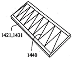
Another aspect of the present technology relates to a mask suitable for use in the treatment of sleep disordered breathing. The mask includes a chamber constructed from a textile, wherein the textile includes pleats constructed and arranged to shape the textile in a three-dimensional form.
Another aspect of the present technology relates to a mask suitable for use in the treatment of sleep apnea. The mask includes: a chamber-forming structure constructed from a textile; a support beam; at least one pipe sleeve; and an exhaust port, wherein the support beam, at least one shroud, and exhaust port are formed as one piece.
Other aspects, features and advantages of the present technology will become apparent from the following detailed description, taken in conjunction with the accompanying drawings, which form a part of this disclosure and illustrate, by way of example, the principles of the present technology.
Drawings
The accompanying drawings facilitate an understanding of various embodiments of the present technology. In the drawings:
1-1 is a side view of a nasal mask system positioned on a patient's face in accordance with an example of the disclosed technology;
1-2 are side views of the nasal mask system of FIG. 1 removed from a patient's face;
figures 1-3 are first perspective views of the nasal mask system of figures 1-2;
figures 1-4 are second perspective views of the nasal mask system of figures 1-2;
FIGS. 1-5 are rear views of the nasal mask system of FIGS. 1-2;
figures 1-6 are front views of the nasal mask system of figures 1-2;
FIGS. 1-7 are top views of the nasal mask system of FIGS. 1-2;
1-8 are bottom views of the nasal mask system of FIGS. 1-2;
figures 1-9 are first exploded perspective views of the nasal mask system of figures 1-2;
figures 1-10 are second exploded perspective views of the nasal mask system of figures 1-2;
FIGS. 1-11 are cross-sectional views taken along lines 1-11-1-11 in FIGS. 1-5;
FIGS. 1-12 are cross-sectional perspective views taken along line 1-12-1-12 in FIGS. 1-5;
FIGS. 1-13 are cross-sectional side views taken along a line similar to line 1-12-1-12 in FIGS. 1-5;
FIG. 2-1 is a front view of a back panel and seal positioned on a patient's face in accordance with an example of the disclosed technology;
FIG. 2-2 is a perspective view of the back panel and seal of FIG. 2-1;
FIG. 3-1 is a vertical cross-section of a mask according to an example of the disclosed technology;
3-1A is a horizontal cross-section of the mask shown in FIG. 3-1 positioned on a patient's face in accordance with an example of the disclosed technology;
3-2 are horizontal cross-sections of a mask positioned on a patient's face in accordance with an example of the disclosed technology;
FIG. 4-1 is a vertical cross-section of a mask according to an example of the disclosed technology;
FIG. 4-1A is a horizontal cross-section of the mask shown in FIG. 4-1 positioned on a patient's face in accordance with an example of the disclosed technology;
FIG. 5-1 is a perspective view of a mask having a raised portion in accordance with an example of the disclosed technology;
FIG. 5-2 is a perspective view of a portion of the mask of FIG. 5-1;
5-2A illustrates the mask portion of FIGS. 5-2 positioned on a patient's face in accordance with an example of the disclosed technology;
5-3 are schematic diagrams illustrating partial cross-sections of a mask positioned on a patient's face in accordance with examples of the disclosed technology;
5-4 are horizontal cross-sections of a mask positioned on a patient's face in accordance with an example of the disclosed technology;
5-5 are partial cross-sectional views of a mask showing padding connected to the mask in accordance with an example of the disclosed technology;
5-6 are partial cross-sectional views of a mask showing padding connected to the mask in accordance with an example of the disclosed technology;
5-7 are partial cross-sectional views of a mask showing padding connected to the mask in accordance with an example of the disclosed technology;
5-8A are perspective views of a mask including padding in accordance with an example of the disclosed technology;
FIGS. 5-8B are top views of the mask of FIGS. 5-8A;
5-8C are cross-sectional views of the mask of FIGS. 5-8A positioned on a patient having a relatively shallow nasal bridge height, in accordance with an example of the disclosed technique;
5-8D are cross-sectional views of the mask of FIGS. 5-8A positioned on a patient having a relatively large nasal bridge height, in accordance with an example of the disclosed technology;
FIG. 6-1 is a vertical cross-section of a mask including a stiffening element according to an example of the disclosed technology;
FIG. 7-1 is a front view of a portion of a mask including a stiffening element according to an example of the disclosed technology;
fig. 7-2 is a perspective view of a portion of a mask including a stiffening element according to an example of the disclosed technology;
7-3 are perspective views of a portion of a mask including a stiffening element positioned on a patient's face in accordance with an example of the disclosed technology;
FIG. 8-1 is a horizontal cross-section of a mask including a stiffening element positioned on a patient's face in accordance with an example of the disclosed technology;
FIG. 8-2 is a horizontal cross-section of a mask including a stiffening element positioned on a patient's face in accordance with an example of the disclosed technology;
FIG. 9 is a schematic view of a mask positioned on a patient having a relatively shallow nose and on a patient having a relatively wide nose;
FIG. 10-1 is a perspective view of a mask system with a multi-layer seal in accordance with an example of the presently disclosed technology;
FIG. 10-2 is an exploded perspective view of a multilayer seal in accordance with an example of the disclosed technology;
FIG. 11-1 illustrates a base layer of a seal positioned on a patient's face in accordance with an example of the disclosed technology;
FIG. 11-2 is a front view of the base layer of FIG. 11-1;
11-3 are front views showing the base layer of FIG. 11-1 being pulled into position on a patient's face in accordance with an example of the disclosed technology;
11-4 are side views illustrating the base layer of FIG. 11-1 pulled into position on a patient's face in accordance with an example of the disclosed technology;
FIG. 12-1 is a front view showing a base layer and a liner layer of a seal in accordance with an example of the disclosed technique;
FIG. 12-2 illustrates the base layer and cushion layer of FIG. 12-1 positioned on a patient's face in accordance with an example of the disclosed technique;
12-3 are schematic illustrations of a cushion including a seal without a cushion layer positioned on a patient's face in accordance with an example of the disclosed technology;
12-4 are schematic illustrations of a cushion including a seal with a cushion layer positioned on a patient's face, in accordance with an example of the disclosed technology;
FIG. 13-1 is a front view illustrating a base layer, a liner layer, and an interface layer of a seal according to an example of the disclosed technology;
FIG. 13-2 is a front view of the interface layer of FIG. 13-1;
FIG. 13-3 is a front view showing the base layer, cushion layer and interfacing layer of FIG. 13-1 pulled into place on a patient's face in accordance with an example of the disclosed technology;
13-4 are side views illustrating the base layer, cushion layer, and interfacing layer of FIG. 13-1 pulled into place on a patient's face in accordance with an example of the disclosed technology;
FIG. 14 shows layers of a seal in accordance with an example of the disclosed technology;
fig. 15-1 is a perspective view of a mask system according to an example of the disclosed technology;
FIG. 15-2 shows the mask system of FIG. 15-1 positioned on a patient's face in accordance with an example of the disclosed technology;
FIG. 15-3 is a front view of the upper and lower panels of the mask system of FIG. 15-1;
FIG. 15-4 is a front view of the upper panel of FIG. 15-3;
15-5 are schematic illustrations of an upper panel positioned on a patient's face in accordance with an example of the techniques of this disclosure;
15-6 are schematic views of a lower panel positioned on a patient's face in accordance with an example of the techniques of this disclosure;
15-7 are front views showing the upper and lower panels of FIG. 15-1 being pulled into position on a patient's face in accordance with an example of the disclosed technique;
fig. 16-1 is an exploded view of a mask system according to an example of the disclosed technology;
fig. 16-2 is an exploded perspective view of a mask system according to an example of the disclosed technology;
fig. 16-3 are perspective views of mask systems according to examples of the disclosed technology;
FIG. 16-4 is a cross-sectional view taken along line 16-4-16-4 of FIG. 16-3;
FIG. 16-5 is a cross-sectional view taken along line 16-5-16-5 in FIG. 16-3;
FIG. 17-1 is a perspective view of a mask according to an example of the disclosed technology;
FIG. 17-2 is a cross-section of the mask of FIG. 17-1;
FIG. 17-3 is a rear perspective view of the mask of FIG. 17-1;
FIG. 17-4 is a side view of the mask of FIG. 17-1 positioned on a patient's face in accordance with an example of the disclosed technology;
17-5 are front views showing the mask portion prior to assembly, in accordance with an example of the disclosed technique;
fig. 18-1 is a perspective view of a mask system according to an example of the disclosed technology;
fig. 18-2 is a perspective view of a mask system according to an example of the disclosed technology;
FIG. 18-3 is a cross-sectional view taken along line 18-3-18-3 of FIG. 18-2;
fig. 18-4A is a front perspective view of a headgear positioned on a patient's face according to an example of the disclosed technology;
fig. 18-4B is a side perspective view of the headgear of fig. 18-4A;
18-5 are perspective views of mask systems according to examples of the disclosed technology;
18-6A-18-6D are perspective views of headgear according to examples of the disclosed technology;
fig. 18-6E are enlarged front views of the headgear fastener of fig. 18-6D.
18-7A-18-7B are perspective views of masks according to examples of the disclosed technology;
FIG. 19-1 is a perspective view of a mask system according to an example of the disclosed technology;
19-2 and 19-3 are front views of a system with a mask positioned on a patient's face in accordance with an example of the disclosed technology;
19-4 and 19-5 are side views of a partial mask system positioned on a patient's face in accordance with an example of the disclosed technology;
fig. 20 is a perspective view of a mask system according to an example of the disclosed technology;
21-1A-21-2 illustrate an air delivery tube according to an example of the disclosed technology;
21-3A are front views of air delivery tubes in accordance with examples of the disclosed technology;
21-3B are enlarged details of a connection between an air delivery tube and a mask in accordance with an example of the disclosed technology;
21-4 are cross-sections of air delivery tubes in accordance with examples of the disclosed technology;
21-5A through 21-5D illustrate a manufacturing process for an air delivery tube in accordance with an example of the disclosed technique;
21-6A are perspective views of air delivery tubes in accordance with examples of the disclosed technology;
FIGS. 21-6B are end views of the air delivery tube of FIGS. 21-6A;
FIGS. 21-6C are perspective views of the support structure of FIGS. 21-6A;
21-7A are front views of tube sheets according to examples of the disclosed technology;
21-7B are perspective views illustrating the tubesheet of FIGS. 21-7A formed in a tube in accordance with an example of the disclosed technique;
21-8A are top views of support structures according to examples of the disclosed technology;
21-8B are end views of an air delivery tube including the support structure of FIGS. 21-8A in accordance with examples of the disclosed technique;
21-9 are perspective views of support structures according to examples of the disclosed technology;
21-10 are perspective views of support structures according to examples of the disclosed technology;
21-11 are perspective views of support structures according to examples of the disclosed technology;
21-12A are perspective views of a support structure according to examples of the disclosed technology;
FIGS. 21-12B are top views of the support structure of FIGS. 21-12A; and
fig. 21-13 are perspective views of a support structure according to an example of the disclosed technology.
Detailed Description
The description provided below relates to several examples (most of which are shown and some of which may not be shown) that may share common features and characteristics. It should be understood that one or more features of any example may be combined with one or more features of other examples. Furthermore, any single feature or combination of features in any one example may constitute further examples.
In this specification, the term "comprising" should be understood in its "open" sense, i.e. in the sense of "having", and is thus not limited to its "closed" sense, i.e. in the sense of "consisting only of. The corresponding meaning should be attributed to the corresponding terms "comprising", "including" and "including" where they appear.
The term "air" will be understood to include breathable gases, such as air with supplemental oxygen. The respiratory therapy devices or blowers described herein may be designed to pump fluids other than air.
One or more instances may include exemplary dimensions. Although specific dimensions and ranges may be provided, it should be understood that these dimensions and ranges are exemplary only, and that other dimensions and ranges are possible depending on the application. For example, a range of +/-10% from the size and range of settings may be suitable for a particular application.
In this specification, any reference to the term "elastic" is defined to mean a material that is capable of springing back or returning to its original shape after being deformed. The time for the material to return or rebound may be less than about 1 second.
In the present specification, touch or feel is defined to mean the quality of a yarn or fabric estimated by a reaction obtained from the sense of touch, which relates to the judgment of roughness, smoothness, roughness, flexibility, thickness, and the like.
Substantially rigid means not easily deformable to finger pressure. Substantially non-rigid means easily deformable to finger pressure.
1.0 mask System
The disclosed examples relate to unobtrusive, comfortable, visually appealing, easily installable, mass-manufacturable mask systems (e.g., nasal mask systems) that provide effective sealing with the patient and/or fit a large portion of the population. Although each of the examples below are described as including a nasal interface, aspects of the present technology may be adapted for use with other suitable interface types, e.g., full-face, oronasal, mouth, pillow, forked, etc.
In accordance with the example of the disclosed technology illustrated in fig. 1-1 through 1-13, a mask system includes a patient interface (e.g., mask 10) adapted to engage a patient's face to seal therewith and deliver breathable gas to the airway of the patient. The patient interface may form a chamber, pouch, or enclosed portion adapted to communicate gas from the exhalation device to the airway of the patient. As shown in fig. 1-2, the mask 10 includes a patient contacting side 12 and a non-patient contacting side 14. As best shown in fig. 1-10 through 1-12, the back panel 20 is joined with the front panel 30 to form a cavity 16 that receives the patient's nose. A seal 40 is attached to the back panel 20 and engages the patient's face to form a seal with the patient's face.
Each side of mask 10 may be coupled to a cuff 50. The cuff 50 is configured to be coupled to an air delivery tube to receive a supply of breathable pressurized gas from the air delivery tube. It should be understood that the mask may be coupled to only one cuff. The sleeve may be sealed by a plunger or sealing device if desired. The mask is preferably held on the patient's face by headgear.
The back panel 20 may be constructed and arranged to be positioned near or proximal to the patient's face. The rear panel 20 has a generally triangular or trapezoidal shape. However, alternative shapes are also possible, such as oval, circular, square, etc. Preferably, the back panel 20 is shaped to provide a visual cue to the patient as to the orientation of the mask. For example, the triangular shape serves to indicate to the patient that the apex of the rear panel 20 is positioned in the nasal bridge region and that the sides of the rear panel are positioned along the cheeks or sides of the nose of the patient.
The back panel 20 may have a generally concave shape that spans the face of the patient (from the left to the right side of the nose). This configuration more readily forms a seal with the patient's face because it anatomically matches the shape of a human face.
The rear panel 20 includes a main body 21, an upper flange 22 along an upper periphery of the main body, and a lower flange 24 along a lower periphery of the main body. The upper flange 22 includes an upper engagement surface 23 and the lower flange 24 includes a lower engagement surface 25. As will be described later, the upper engagement surface 23 sealingly engages with the lower engagement surface 25 and is coupled to a corresponding surface of the front panel 30 to form the mask 10. An opening 26 is formed in the body 21 of the back panel 20 and is configured to receive the patient's nose and allow the passage of breathable gas to the patient's airway. The opening 26 may have a generally triangular shape, or any other suitable configuration.
As shown in fig. 1-9 and 1-10, the body 21 of the rear panel 20 preferably has a curvature from the upper flange 22 to the lower flange 24. The curved portion creates a space forming the cavity 16 together with the front panel 30. The left and right portions of the body may include cuff attachment surfaces 28 and 38 that sealingly engage the cuff 50. As shown in fig. 1-11 and 1-13, the body 21 of the back panel 20 includes an engagement portion 21-1 in sealing engagement with the seal 40.
In an alternative arrangement, the body 21 of the back panel 20 may be substantially flat or planar and may be curved or conform to the curvature of the patient's face.
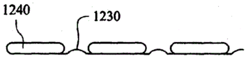
As best shown in fig. 1-10, the upper flange 22 may be angled to form a central apex adapted to conform to the nasal bridge region of the patient's face. The lower flange 24 may be shaped to fit the upper lip and lower portion of the nose of the patient. For example, as best shown in fig. 1-9, the lower flange 24 may include at least two bends or undulations 27, the bends or undulations 27 having a central portion 29 that forms a lower limit (lower extent) of the undulations 27. The central portion 29 may form a convex curvature adapted to accommodate a patient's septum or a region in a person.
The back panel 20 may be constructed of a textile. This fabric may be an air retaining textile or a sealing textile that does not allow gas to pass through its fibers. For example, the textile may be a composite material having a first fabric layer and a second polymer layer (i.e., a coated textile). The second polymer layer may be a film, spray coating, or other arrangement suitable for sealing the first layer.
Since the back panel 20 may contact the patient's face, the fabric is preferably soft and comfortable. Thus, the fabric may be a soft textile such as cotton, satin, micro-pile, nylon, fleece, velvet, corduroy, and the like. Bedroom environmentally friendly materials on the outer surface aid in patient compliance as these materials increase the comfort and desirability of the mask. This also gives the mask a more attractive non-medical appearance to the patient. The polymer may be, for example, polyurethane, polyester, silicone, nylon, or the like.
In an example, the back panel 20 has a height (e.g., from the central portion 29 to the apex of the upper flange 22) of about 45-80mm (e.g., 50-70mm, or about 60mm, or about 65 mm).
In an example, the back panel 20 can have a height (e.g., from one end of the lower flange 24 to the other end of the lower flange 24) of about 80-120mm (e.g., 90-110mm, or about 100mm, or about 96 mm).
In an example, the opening 26 has a height of about 20-50mm (e.g., 35-60mm, or about 35mm, or about 40 mm).
In an example, the opening has a width of about 20-50mm (e.g., 25-45mm, or about 35 mm).
The front panel 30 is positioned on the non-patient contacting side of the mask 10. The front panel 30 generally forms a triangular or trapezoidal shape, although other suitable shapes such as oval, circular, square, etc. may also be used. Preferably, the front panel 30 has a shape similar to that of the rear panel 20.
As best shown in fig. 1-9 and 1-10, the front panel 30 includes a body 31, an upper flange 32 along an upper perimeter of the body, and a lower flange 34 along a lower perimeter of the body. The upper flange 32 includes an upper engagement surface 33 and the lower flange 34 includes a lower engagement surface 35. The upper and lower engagement surfaces 33, 35 sealingly engage and couple to the upper and lower engagement surfaces 23, 25 of the back panel 20 to form the face mask 10.
As shown in fig. 1-1, 1-10, and 1-11, the body 31 of the front panel 30 preferably has a curvature from an upper flange 32 to a lower flange 34. The curvature helps create a space for cavity 16 to receive the patient's nose. The sides of the body 31 may include a sleeve attachment surface 38 in sealing engagement with the sleeve 50.
As best shown in fig. 1-6, the upper flange 32 may be angled to form a central apex that fits over the nasal bridge region of the patient's face. The lower flange 34 may be shaped to fit the upper lip and lower portion of the nose of the patient. For example, as best shown in fig. 1-9, the lower flange 34 may include at least two bends or undulations 37, the bends or undulations 37 having a central portion 39 that forms a lower limit of the undulations 37. The central portion 39 may form a convex curvature adapted to accommodate the septum or the area in the person of the patient.
The front panel 30 may be constructed of a textile. The textile may be an air retaining textile or a sealing textile that does not allow gas to pass through its fibers. For example, the textile may be a composite material having a first fabric layer and a second polymer layer (i.e., a coated textile). The second polymer layer may be a film, spray coating, or other arrangement suitable for sealing the first layer. In an alternative form, the front panel 30 may be constructed or formed from a transparent or substantially transparent material including, for example, polycarbonate, polypropylene, or silicone, so that the patient's nose may be visible to the clinician.
The front panel 30 may include an exhaust portion. For example, an exhaust port portion (such as a vent tube or insertable exhaust component) may be sealingly attached to the front panel 30. The vent member may be substantially rigid or semi-rigid to keep the vent open and reduce venting noise. Alternatively, the fabric of the front panel 30 may be selectively sealed such that a portion of the fabric is non-airtight, thereby functioning as an air vent.
In use, when positive air pressure is applied within the mask, a seal made of a thin material (e.g., a flap seal made of a textile and/or elastomer in this example) may have a self-sealing action, which may stiffen the textile of the front panel 30, thereby creating a larger space for receiving the patient's nose.
In an example, the front panel has a height of about 45-80mm (e.g., 50-70mm, or about 60mm, or about 65 mm).
In an example, the front panel 30 has a width (e.g., from one end of the lower flange 34 to the other end of the lower flange) of about 80-120mm (e.g., 90-110mm, or about 100mm, or about 96 mm).
As shown in fig. 1-2, in an example, the front panel 30 has a radius of curvature a of about 10-30mm (e.g., 10-25mm, or about 15 mm) along the vertical axis.
As shown in fig. 1-7, in an example, the front panel 30 has a radius of curvature β of about 10-30mm (e.g., 10-25mm, or about 15 mm) along a horizontal axis.
Preferably, the fabric is visually appealing because the front panel 30 is most visible when the mask is in use. The fabric may be, for example, a soft, seemingly unwieldy textile such as nylon, cotton, linen, dazzling, silk, etc. The polymer may be polyurethane, polyester, silicone, nylon, or the like.
The rear panel 20 and the front panel 30 may be integrally formed. The rear panel 20 and the front panel 30 may be sealingly joined by welding, heat pressing, or other methods. Alternatively, the back panel 20 and the front panel 30 may be sealingly joined by stitching or other suitable methods.
In an example, the upper flange 22 of the rear panel 20 and the upper flange 32 of the front panel 30 may be aligned. Likewise, the lower flange 24 of the rear panel 20 is aligned with the lower flange 34 of the front panel 30. The upper joining surfaces 23, 33, and the lower joining surfaces 25, 35 of the rear panel 20 and the front panel 30 may be welded together using radio frequency welding or ultrasonic welding. Radio frequency welding can form a more robust seal, which is preferable in forming a hermetic chamber. Preferably, the weld may be three-dimensional to ensure that the shape of the mask 10 is three-dimensional. In other examples, the radio frequency weld may be formed first and then the ultrasonic cut may be performed. Ultrasonic cutting may round the edges of the textile or bend in other placements to prevent facial marking and thereby increase patient comfort.
In an example, the upper and lower joining surfaces 23, 25 of the back panel 20 and the upper and lower joining surfaces 33, 35 of the front panel 30 have a width of about 1-10mm (e.g., 2-6 mm).
Headgear may be attached or otherwise connected to the mask. Alternatively, the headgear may be formed with the front panel 30 and/or the rear panel 20 or as part of the front panel 30 and/or the rear panel 20.
The stiffener (or stiffening element) may be formed with the front panel 30 and/or the back panel 20 or attached to the front panel 30 and/or the back panel 20. The stiffening member may provide structural stability and support for the mask 10. For example, the rigid member may be a semi-rigid or rigid component such as a polymeric shaft or frame. For example, the stiffener may be positioned in the nasal bridge region (to ensure sealing of the nasal bridge region and/or sides of the patient's nose near the nasal bridge region of the patient's face, as the curvature of the patient's face in this region is particularly difficult to seal), the upper lip region and/or corners of the nose of the patient's face. In addition, the rigid member may be interconnected with the tube housing 50.
As best shown in fig. 1-5 and 1-10, the seal 40 is adapted to sealingly engage the patient's face. The seal 40 includes a body 41 and an opening 46 formed in the body. The main body 41 includes a connecting portion 41-1, the connecting portion 41-1 being sealingly engaged with the engaging portion 21-1 of the rear panel 20 or otherwise attached to the engaging portion 21-1 of the rear panel 20.
The seal 40 may be constructed and arranged to be positioned adjacent and in sealing engagement with the airway of a patient. The seal 40 may have a generally triangular or trapezoidal shape. Additional shapes are possible (e.g., oval, circular, square, etc.). Preferably, the seal 40 is shaped to provide a visual cue to the patient as to the positioning of the mask. For example, the triangular shape serves to indicate to the patient that the apex of the seal 40 will be positioned near the nasal bridge region.
The opening 46 formed in the body 41 of the seal may have a triangular or tri-lobed shape, although other suitable shapes may be used.
The seal 40 may be constructed of a polymer. Preferably, the polymer may have a low stiffness so as to easily conform to and conform to the shape of the patient's face. For example, the polymer may be a silicone, thermoplastic elastomer, polyurethane, or the like having a Shore A or Shore A hardness of 5-20 and a thickness of about 0.3-2mm (e.g., a Shore A hardness of 5-10 and a thickness of 0.3-2 mm). The polymer may be of shore 00 hardness, for example 20-40, or a low hardness of shore 00 hardness.
In other alternatives, the sealing member 40 may be constructed of a tacky or sticky material to better grip the patient's face and thereby form a more secure seal. The tackiness may be provided by surface polishing, application of an adhesive, or by virtue of material properties (e.g., low durometer silicone, such as silicone having a shore 00 hardness of 5-20 or a shore 00 hardness that is inherently tacky).
In other alternatives, the seal 40 may be constructed of a textile. Alternatively, the seal 40 may be constructed from a combination of materials such as adhesive materials and textiles.
As described above, the seal 40 is sealingly engaged with the rear panel 20. The seal 40 may be thermoformed, overmolded, bonded, welded or otherwise attached to the back panel 20. Preferably, the connecting portion 41-1 of the sealing member 40 overlaps the engaging portion 21-1 of the rear panel 20 to ensure that the sealing member 40 is sealingly engaged with the rear panel 20 to prevent a leakage path. In an example, the overlap can be about 1-10mm wide (e.g., 2-6 mm).
In an example, the seal 40 has a height of about 30-60mm (e.g., 40-60mm, or about 55mm, or about 45 mm).
In an example, the seal 40 has a width of about 50-80mm (e.g., 60-70mm, or about 65mm, or about 53 mm).
In an example, the seal opening 46 has a height of about 15-35mm (e.g., 20-30mm, or about 25mm, or about 30 mm).
In an example, the seal opening 46 has a width of about 20-40mm (e.g., 30-40mm, or about 35 mm).
As best shown in fig. 1-5 and 1-9, the mask system may include one or more cuffs 50 coupled to the sides of the mask 10. The cuff may be a male cuff (i.e., protruding from mask 10) or may be a female cuff (i.e., received within the confines of mask 10). In the example shown, the sleeve 50 is a male sleeve. Each sleeve 50 includes a main body 51 and a flange 54. A hollow portion 52 is formed by the body 51 and the flange 54 to allow the passage of breathable gas supplied by the air delivery tube. As shown in fig. 1-1 and 1-10, the flanges are configured to sealingly engage the socket attachment surfaces 28, 38 of the back and front panels 20, 30, such as by bonding, thermoforming, or welding (e.g., radio frequency, ultrasonic).
The shroud 50 may have a generally tubular shape, such as a shape having an oval cross-section. Other shapes and cross-sections such as circular, square with rounded corners, rectangular, oval, etc. may also be used.
The flange 54 may also assist in positioning the air delivery tube. For example, the air delivery tube may be slid over the tube sleeve 50 until the air delivery tube reaches a flange 54 that may be arranged to indicate that the air delivery tube is properly positioned.
The sleeve 50 may be constructed of a polymer. Preferably, the polymer may be semi-rigid or rigid to ensure that air delivered from the air delivery tube to the mask 10 is not restricted. The tube sleeve 50 may be constructed of nylon, polypropylene, polycarbonate, for example.
In an example, the sleeve 50 has an internal width along its longest axis of about 15-25mm (e.g., about 20 mm).
In an example, the sleeve 50 has an internal width along its shortest axis of about 5-15mm (e.g., about 8.5 mm).
In an example, the sleeve 50 has a thickness of about 1-3mm (e.g., about 2.5mm, or about 1.5 mm).
A single air delivery tube may be connected to one tube sleeve 50 while the other tube sleeve 50 is sealed by a plunger (not shown). Alternatively, two air delivery tubes may be connected to the two tube sleeves 50, respectively.
A headgear may be attached to the tube sleeve 50. The headgear may be formed as a conduit for delivering breathable gas to the cuff 50.
The exhaust ports may be provided in one or both of the sleeves or connecting portions 50. The exhaust port may include a series of holes adapted to exhaust gases (e.g., CO 2) from the mask 10. Preferably, the sleeve is substantially rigid or semi-rigid to maintain the vent opening and reduce vent noise.
The cuff may preferably be configured as a female cuff to reduce the size of the mask 10, to make it easier to connect with a tube and to allow the tube or connector (connector adapted to connect to the female cuff) to have a release button to perform attachment and detachment through the tube or connector rather than the cuff.
The sleeve may be included in the headgear (e.g., forming part of the headgear rigid member). The sleeve may also provide a connection point to a headgear or headgear connector.
2.0 sealing arrangement
In the example shown in fig. 2-1 and 2-2, the seal 40-1 is coupled to the back panel 20-1, and the seal 40-1 and back panel 20-1 include openings to receive the patient's nose. The front panel is removed from these views for illustrative purposes.
The back panel 20-1 may form a soft contact surface (e.g., wool or fleece) for interacting with the patient's skin Finished product). A thickened cushion portion may be formed in the back panel 20-1 around high pressure areas, such as the nasal bridge area and upper lip area, to enhance comfort. Additionally, the back panel 20-1 may also include a rigid portion to provide support and/or shape to the back panel.
A headgear 60 including straps 62 may be attached to the rear panel 20-1. The headgear may be adjustable by loop tabs or other attachment structure and/or may be self-adjusting by providing elasticity in the straps 62.
The sealing member 40-1 is configured as a thin elastomeric member and may be formed, for example, from a textile, a polymer (e.g., silicone, polyurethane), or a combination thereof, by, for example, lamination or overmolding. The thin elastomeric seal 40-1 is arranged to conform to the shape of the patient's face (e.g., nose). The force exerted by the headgear 60 on the back panel 20-1 and in turn on the seal 40-1 further causes the seal 40-1 to conform to the shape of the patient's nose and/or face. The seal is also actuated by the pressure of the breathable gas in the chamber forming part (or cavity) and preferably may have a high level of flexibility to enable the seal to more easily correspond to the system pressure inside the mask. When positive pressure is applied within the mask, there is a self-sealing action of the seal to engage and conform to the shape of the patient's nose to form a seal with the patient's nose.
An unsupported length seal (i.e., a substrate or other material without a back panel) allows the seal to move freely and bend more easily to conform to the shape of the patient's face.
In accordance with examples of the disclosed technology, the seal may be positioned on the mask by attachment to the back panel or may be otherwise formed on the back panel or other suitable surface of the mask (or formed as part of the back panel or other portion of the mask). The seal may include a variety of configurations, and when used with the back panel, the seal and back panel may be configured separately or joined together in a variety of ways to form a variety of structures or sealing arrangements that interact with the patient's face to form a seal therewith and ensure efficient delivery of breathable gas to the patient's airways.
For example, instead of a separate seal, the seal may be formed as part of the back panel. Additionally, a support padding may be included in the mask to enhance comfort and/or improve the quality of the seal around difficult areas to seal voids such as on the sides of the nose. Further, portions of the mask may include rigid structures. In the following section, several such configurations or arrangements are described. It is to be understood that any feature described in relation to one example may be used or combined with another feature in different examples.
2.1 Individual seal
In the example shown in fig. 3-1, the seal 40-2 is coupled to the back panel 20-2. The seal member 40-2 may be welded to the rear panel 20-2 or co-molded with the rear panel 20-2. As best shown in fig. 3-1A, the seal is flexible to conform to the face and/or nose of the patient. The seal includes a first end 40-2 (1) connected to the back panel and a second end 40-2 (2) that seals against the face and/or nose of the patient. For example, the seal may be formed of silicone or polyurethane, and may also include a single wall construction or a double wall construction.
In other examples shown in fig. 3-2 and in contrast to seal 40-2, the cross-section of seal 40-3 has an S-shaped cross-sectional shape with a first end 40-3 (1) connected to back panel 20-3 and a second end 40-3 (2) positioned to seal against the patient' S face and/or nose. The S-like shape of the seal 40-3 causes the seal to act as a resilient member. This spring action helps to cause the seal member to exert a spring force against the patient's face. The spring force may enable the sealing member 40-3 to better conform to the curvature of the patient's face and/or nose, which may improve the quality of the seal and comfort to the patient by making the pressure on the face more gradual.
First end 40-3 (1) may be thickened to increase support, while second end 403- (2) may be thinned to increase the flexibility of sealing member 40-3, which may enable the sealing member to better conform to the curvature of the patient's face and/or nose.
2.2 rear Panel with Integrated seal
As shown in fig. 4-1, in an example, the seal 40-4 may be formed as part of the back panel 20-4. The textile portion forming the sealing member 40-4 may be thinner than the back panel 20-4 to increase compliance with the patient's facial features. This arrangement may reduce manufacturing complexity, cost and may make the mask more visually pleasing.
2.3 elevated seal arrangement
Referring to fig. 5-1 through 5-8B, the cushion may include raised (i.e., protruding) portions that may enhance comfort and improve sealing against the patient's face, particularly in areas that are difficult to seal.
As shown in FIG. 5-1, the mask 10-1 includes a front panel 30, a rear panel 20-5 coupled to the front panel, a raised portion 90 disposed on the rear panel 20-5, and a seal 40-5 formed or positioned on the raised portion 90. As best shown in fig. 5-2, wherein the rear panel 20-5 is removed from the front panel 30, the rise 90 includes a padded portion, padding or padding member 92, which may be formed of foam, for example. The foam may be a silicone foam (e.g., a low density, low hardness, and/or washable silicon foam). Other foam or padding providing materials (e.g., polyurethane foam, open or closed cell foam, foam with or without a skin, gel, spacer fabric, and/or packing material) may also be used.
As shown in fig. 5-2A and 5-3, as the mask 10-1 wears, the raised portion 90 protrudes toward the patient's face and extends through the compression padding 92 into the difficult-to-seal area, such as the void on the side of the nose. In other words, the sealing member 40-5 is better able to conform to the curvature on the patient's face because the padding provides a light weight evenly distributed force on the sealing member 40-5. As such, the quality of the seal with the patient's face may be enhanced. In addition, the padding 92 improves patient comfort as the padding 92 provides a cushioning effect for pressure points (e.g., above the upper lip and at the bridge of the nose). In other alternatives, the cushion portion or padding 92 may be shaped to match the contours of the patient's face.
In another example, the back panel may form an enclosure (or receiving cavity) to receive the dunnage.
Specifically, as shown in fig. 5-5, the back panel 20-6 includes an inner layer 20-6 (1) and an outer layer 20-6 (2). The inner layer 20-6 (1) may be a coated fabric layer (e.g., a fabric with a polyurethane coating) for providing air-tightness. The outer layer 20-6 (2) may provide a soft outer surface that interacts with the patient's skin. The outer layer 20-6 (2) may be separated from the inner layer 20-6 (1) to form a receiving portion 94-1 (e.g., a concave or U-shaped configuration). The receiving portion 94-1 and the inner layer 20-6 (1) together form a receiving cavity 95 that receives the mat 92. Further, the seal 40-6 may have a first end 40-6 (1) connected to the receiving portion 94-1 and a second end 40-6 (2) extending radially inward from the receiving portion 94-1. The seal member 40-6 may be attached to the receiving portion 94-1 by injection molding, compression molding, adhesives, ultrasonic welding, or other techniques. The edges of the junction between the inner layer 20-6 (1) and the outer layer 20-6 (2) may be rounded by ultrasonic welding or other techniques to maximize patient comfort and the overall visual appearance of the mask. The arrangement shown in fig. 5-5 may be advantageous because the dunnage is packed and thus can be kept cleaner; furthermore, this entire device may look neater, be more visually appealing, and also be easy to manufacture.
In other examples shown in fig. 5-6, the rear panel 20-7 includes an inner layer 20-7 (1) and an outer layer 20-7 (2). The inner layer 20-7 (1) and the outer layer 20-7 (2) may have the same constitution as described above with respect to the rear panel 20-6. The outer layer 20-7 (2) is separated from the inner layer 20-7 (1) to form a receiving portion 97-1 (e.g., an L-shaped configuration). Likewise, the inner layer 20-7 (1) is separated from the outer layer 20-7 (2) to form a receiving portion 97-1 (e.g., an L-shaped configuration). The receiving portions 94-2, 97-1 together form a receiving cavity 95 that receives the mat 92.
The outer layer 20-7 (2) may extend beyond the cavity 95 to form a connecting lip 121. The inner layer 20-7 (1) may have an attachment lip 122 that is joined to the attachment lip 121 of the outer layer 20-7 (2) to form a mounting structure 124 for the seal 40-7. The seal 40-7 includes a first end 40-7 (1) connected to the mounting structure. The first end portion 40-7 (1) includes a first leg 152, a second leg 154, and a receiving space 155 between the first leg 152 and the second leg 154. The receiving space 155 is configured to receive the mounting structure 124 to secure the seal 40-7 to the back panel 20-7. The first leg 152 may have a length that enables the first leg 152 to abut against the inner layer 20-7 (1) of the back panel 20-7, whereas the second leg 154 may have a length that is greater than the first leg 152 such that the second leg 154 extends along the outer layer 20-7 (2) of the back panel 20-7 a sufficient distance to ensure stable mounting of the seal 40-7 to the back panel 20-7. This arrangement may be preferred as the foam is encapsulated and thereby shielded or protected from dirt and other undesirable materials. In addition to having multiple planar surfaces in contact with the back panel 20-7, the seal 40-7 may be more securely attached to the back panel 20-7 because a larger surface area is in contact with the back panel and the edge (e.g., mounting structure) of the joint between the inner layer 20-6 (1) and the outer layer 20-6 (2) may be utilized to attach the seal 40-7 and thereby support a portion of the seal 40-7.
In another example, the seal 40-7 may be configured and attached to the back panel 20-7 in the same manner as described above with respect to the seal 40-6 and the back panel 20-6.
As shown in fig. 5-7, in another example, the padding 92 is molded, glued, or otherwise attached to the back panel 20-8. The back panel 20-8 forms a receiving portion 97-2 (e.g., an L-shaped configuration). The padding 92 (e.g., silicone foam) is molded onto the receiving portion 97-2 such that the upper surface 92 (1) and the first side surface 92 (2) of the padding 92 engage the rear panel 20-8, while the lower surface 92 (3) and the second side surface 92 (4) are exposed from the rear panel 20-8. This arrangement may be advantageous because less material is required (i.e., no front panel) and the foam may contact the patient's face, which may be comfortable for the patient to wear. Since this foam is exposed, it can be used as an end-of-life indicator (i.e., once the foam becomes dirty, it will be used as an indicator to get the patient to a new mask).
Referring to fig. 5-8A and 5-8B, the sealing arrangement may be configured to accommodate anthropometric variations in nasal depth. For example, the sealing arrangement may be configured to comfortably fit patients having a shallow depth of the nose bridge as well as those having a greater depth of the nose bridge. A patient having a shallow nasal bridge depth d1 is shown in FIGS. 5-8A, and a patient having a larger nasal bridge depth d2 is shown in FIGS. 5-8B. In other words, d1 is smaller than d2.
The padding 92 may be attached to the rear panel 20-9. As shown in fig. 5-8C and 5-8D, the padding 92 in the upper lip region may be thicker than the padding in the nasal bridge region. That is, the nasal bridge region may have little to no padding and a longer membrane compared to the upper lip region. Since this type of seal can more easily accommodate varying anthropometry, the seal in the nasal bridge region is preferably a diaphragm or flap type seal. Further, the diaphragm-type seal may extend toward and be directly connected to or adjacent to the front panel to maximize space for the bridge of the nose of the user. Preferably, there is more foam and less membrane in the side and upper lip areas of the nose to allow for a compression type seal (so that the foam can be compressed into voids and folds, particularly in the corners of the nose, to facilitate sealing in these areas). The foam may also be more comfortable in these areas. In other examples, the foam may have the same depth around the perimeter of the sealing portion to form a compression type seal all the way around the patient's nose.
In the example shown in fig. 5-8A through 5-8D, the seal 40-9 is also connected to the mat 92. The seals 40-9 have a U-shaped configuration at least in the nasal bridge region of the patient's face. The first end 40-9 (1) of the sealing member 40-9 is connected to the padding 92 and the second end 40-9 (2) of the sealing member 40-9 is arranged to engage the patient's face. The first end 40-9 (1) and the second end 40-9 (2) generally form legs of the U-shaped seal 40-9. This configuration may enable the sealing members 40-9 to extend to the face of a patient having a shallow nasal depth. Further, when the U-shaped configuration is positioned on a patient having a greater nasal bridge depth, the U-shaped configuration allows the seal 40-9 to collapse and conform to the patient's face (i.e., the first end 40-9 (1) and the second end 40-9 (2) are proximate to each other). The seal may have a preformed curvature so that collapse is controlled.
The padding 92 acts to evenly distribute the pressure against the sealing members 40-9, thereby improving patient comfort. The U-shaped seals 40-9 may be defined to the region of the seal closest to the nasal bridge region, as this region tends to vary significantly from patient to patient. In other areas of the seal that are generally positioned at or near the patient's upper lip (fig. 5-8C and 5-8D), the seal 40-9 may be substantially flat, as this area tends to have less anthropometric variation.
2.4 rigid Structure
In accordance with the techniques of this disclosure, a rigid structure may be included in the mask to provide, for example, support, shape, form, and/or strength to the mask and prevent deformation of the mask. Furthermore, the rigid element may be interconnected with two or more other rigid components, to ease manufacturing of the rigid components and to stabilize and position the rigid components relative to each other. The rigid member may form a support band. The rigid member may be flat and capable of bending to a certain curvature or may be pre-formed in a curved manner. The stiffener may be constructed and arranged to support a portion of the mask, as the mask itself may not be able to support its own weight or may not be able to support an applied force (e.g., a tube drag force).
Referring to fig. 6-1, the mask includes a layered rigid frame 70 on top of the back panel 20-2. The rigid frame 70 includes side portions 70 (2) that extend along the sides of the mask adjacent the cuff. In an example, the side portion 70 (2) may be connected to the tube sleeve 50. The interconnecting portion 70 (1) extends across the upper lip area of the patient and bridges or interconnects with the side portion 70 (2). The interconnecting portion 70 (1) may cause the back panel 20-2 and/or the sealing member 40-2 to engage the patient's face more stably in the upper lip region. This may enhance the seal with the patient's face. In addition, by extending the rigid frame 70 to both sides of the mask, the rigid frame 70 resists deformation of the mask that may result from over-pulling the straps.
Referring to fig. 7-1 through 7-3, the rigid frame 72 is shown positioned on the back panel 20-2. The rigid frame 72 includes: a cheek portion 72 (2) configured to be placed adjacent a cheek of a patient; sides 72 (3) of the nose extending from cheek portions 72 (2) partially across the patient's nose in the direction of the bridge of the nose; and an interconnecting portion 72 (1) extending across the upper lip region of the patient that bridges or interconnects with cheek portions 72 (2). The interconnecting section 72 (1) functions similarly to the interconnecting section 70 (1) described above.
A gap may tend to form between the rear panel 20-2 (and/or the seal 40-2) and the patient's face in the portion extending between the bridge of the nose and the cheeks of the patient. The sides 72 (3) of the nose, shown on the left and right sides of the mask, provide support and shape to the back panel 20-2 and seal 40-2 in this area. The sides 72 (3) of the nose may have a curvature similar to the curvature of the patient's face (from the patient's cheeks to the nasal bridge), which may force the back panel 20-2 and/or seal 40-2 to conform to the curvature of the patient's face to reduce or prevent leakage. For example, the slot 72 (4) may be formed as part of the rigid frame 72 and may receive a headgear strap or may be configured as a connector to a conduit sleeve.
Referring to fig. 8-1, in an example, a rigid frame 74 can extend from the tube sleeve 50-1. Rigid frame 74 may be a separate member connected to cuff 50-1 or may be integrally formed with the cuff. In another example shown in fig. 8-2, the rigid frame 76 may extend from the tube sleeve 50-2 and additionally include an interconnecting portion 76 (1), which interconnecting portion 76 (1) is layered against the front panel 30 and bridges or interconnects with the tube sleeve 50-2 to provide shaping, form and resist deformation that may result from over-pulling the strap.
In another example, the first end 40-3 (1) of the seal 40-3 in fig. 3-2 may be thickened to serve as a rigid frame.
For example, the rigid frame may be overmolded, bonded, or welded to the panel prior to assembly. They may also form a separate removable component that is inserted into the mask after it is assembled.
The rigid frame may be rigid or semi-rigid. For example, the rigid frame may be made of a flexible semi-rigid plastic such as polypropylene, nylon, polycarbonate, and the like. Further, the face mask may be stiffened by laminating a high density foam having textile panels (e.g., a front panel and a back panel). These laminated structures may also be thermoformed to increase form and strength (e.g., by changing the thickness of the laminated structure and/or by adding specific design features such as ribs).
Stiffening or strengthening of the mask may also be achieved by using non-elastic textiles (e.g., in the front and back panels). Non-elastic textiles may form a mask or may be added strategically to a mask to achieve a desired stiffening or strengthening effect. This non-elastic textile may prevent over-extension in a direction (e.g., across the upper lip area) that may result in deformation of the mask, or more specifically, the front panel, back panel, and/or seal.
In an example, a rigid frame may be used restrictively to maintain a lightweight, soft, and comfortable feel of a textile mask. Furthermore, the use of a rigid frame over sensitive areas such as the nasal bridge and upper lip area may be avoided to improve patient comfort by reducing pressure loads in these areas.
In other alternatives, the rigid frame may be positioned to cover the bridge of the nose, the upper lip, or other sensitive areas; however, they may be constructed and arranged to avoid contact with sensitive facial areas of the patient. That is, the rigid frame may be lifted, raised, or bent away from the patient's face, thereby avoiding contact with sensitive areas while still serving to stabilize and/or strengthen the mask and/or support the mask shape.
2.5 face mask configured to fit a wide range of nose sizes
As shown in FIG. 9, the width d5 of the opening in the back panel 20-1 is designed to accommodate most of the nose size so as to fit one mask size to most of the user population. When the sealing member 40-1 extends sufficiently radially inward from the rear panel 20-1, the width d5 is wide enough to fit the width d4 of the wide nose portion such that the width d1 of the opening of the sealing member 40-1 in its unstretched state is sufficient to form a good seal against the narrow nose portion (having a width d 2).
Furthermore, the sealing membrane is preferably made of a thin, highly extensible member (e.g., textile, silicone, or polyurethane membrane) to stretch (to width d 3) without occlusion to accommodate the width d4 of the wide nose.
The back panel 20-1 serves to hold the seal member 40-1 in a good shape and helps to pull the seal member 40-1 down onto the patient's face.
2.6 multilayer seal
Referring to fig. 10-1, the mask system 100 may include a mask 110 having a multi-layer seal 140. The mask system 100 includes headgear 160 and an air delivery tube for supplying breathable gas to the mask 110. The headgear includes straps 162 that are connected to the mask 110 (e.g., back panel and/or front panel). The strap 162 may be continuous or may include two straps with adjustable connections. In either arrangement, the strap 162 has a single vector V1 (the vector for only one side of the mask is shown).
The mask 110 includes a back panel 120 having a seal 140 attached thereto. The mask may also include a front panel (not shown). The mask forms a cavity for receiving the patient's nose to deliver breathable gas to the patient's airway. The seal 140 is arranged to seal against the patient's face and/or nose when the patient's nose is received in the cavity. As shown in fig. 10-2, the seal 140 includes a base layer 141 attached to the back panel 120, an interface layer 145 for contacting the patient's face, and a cushion layer or pad portion 143 disposed between the base layer 141 and the interface layer 145.
Referring to fig. 11-1 and 11-2, the base layer 141 has a substantially triangular shape; however, other shapes may also be used. An opening 141 (1) is formed in the base layer 141 to receive the patient's nose. The opening 141 (1) may also have a generally triangular shape, although other shapes may also be used. The opening 141 (1) is intended to fit the patient's nose.
The width d1 of the opening 141 (1) is made smaller than the average/standard anthropometric measurement to require the base layer 141 to stretch (by tension from the strap 162) in order to receive the patient's nose. As shown in fig. 11-3, the height d2 of the opening 141 (1) is sized such that the upper portion of the base layer 141 rests on the lower end of the bridge of the nose, which prevents the mask from obstructing the patient's vision. The width d1 may have a length of about 25-60mm, such as about 30-45mm, such as about 40mm. The length of the height d2 may be about 15-50mm, such as about 20-40mm, such as about 30mm.
When tension is received from the strap 162, the seal 140 is pulled into sealing engagement with the patient's face. In particular, the base layer 141 acts to cause the seal 140 to effect a seal in the upper lip and nasal bridge region. As shown in fig. 11-3 and 11-4, the upper lip seal region 141a spans the upper lip of the patient and extends to the corners of the nose. The nose bridge sealing region 141b is positioned at the lower end of the nose bridge.
The base layer 141 may be made of a highly stretchable, air-impermeable material such as a Thermoplastic Polyurethane (TPU) film. The base layer 141 may also be made of a dense extensible fabric such as nylon Long Laika. Other suitable materials may also be utilized. The stretchability and elasticity of the base layer 141 causes the base layer 141 to press against the patient's face when tension is applied. This action pushes the interface layer 145 against the patient's face to effect a seal in the upper lip sealing region 141a and the nose bridge sealing region 141 b.
The cushion layer 143 preferably has a perimeter geometry that is the same as the perimeter geometry of the base layer 141. The gasket layer 143 has a raised (or thicker) profile and is intended to provide a gasket for the seal 140. The opening 143 (1) in the pad layer 143 has a width d3 and a height d4 that substantially correspond to the width d1 and the height d2 of the opening 141 (1) in the base layer 141.
As shown in fig. 12-3, when the seal 140 is pulled taut across the bridge of the nose, the portion of the seal that spans the sides of the nose tends to lift from the patient's face to form a gap 177 (or potential leak path) between the seal 140 and the patient's face (e.g., the sides of the nose). As shown in fig. 12-4, the cushion layer 143 functions to provide "mass" against the sides of the nose to fill the gap 177 while also providing padding over the bridge of the nose.
The interface layer 145 is disposed in contact with the patient's face. As shown in fig. 13-1 and 13-2, the interface layer 145 includes an opening 145 (1) for receiving the patient's nose. The opening 145 (1) has a substantially inverted T-shape and includes a central cutout 145 (l) a having a substantially triangular shape, an upper slit 145 (l) b vertically extending from an upper portion of the central cutout, and lower slits 145 (l) c, 145 (l) d extending from lower left and lower right sides of the central cutout 145 (l) a. It should be noted that the opening 145 (1) may have other shapes.
The width d5 of the opening 145 (1) may be greater than the width d1 of the opening 141 (1) in the base layer 141. This arrangement may assist in pressing the cushion into sealing engagement with the corners of the patient's nose. That is, the base layer may provide support and additional force to press and stretch into the void located at the side of the patient's nose. The width d5 may be about 1-5mm less than the width d1. The height d6 of the opening 145 (1) may be equal to or less than the height d2 of the opening 141 (1) in the base layer 141.
Opening 145 (1) in interface layer 145 forms two flaps 176, 178. When the patient's nose enters the cavity formed in the mask 110, flaps 176, 178 fold and fit against the sides of the patient's nose to effect a seal. As shown in fig. 13-3 and 13-4, each flap 176, 178 tightly seals the patient's face along the sides of the nose in the sides of the nose sealing region 176a, 178 a. The tension applied by the strap 162 causes the interfacing layer 145 to be pulled in tension across the upper lip and the nasal bridge to effect a seal in the upper lip sealing region 141a and the nasal bridge sealing region 141 b.
The interface layer 145 may be made of a comfortable textile. Preferred material properties for the interfacing layer material include minimal stretch, air-tightness, conformability to the patient's face, and/or the ability to provide a comfortable interface to the patient's face. The minimal stretchability of the interfacing layer 145 provides a defined wall that anchors the seal around the nares.
The base layer 141, cushion layer 143, and interface layer 145 may be joined together by radio frequency welding, ultrasonic welding, stitching, seam tape, adhesive, heat staking, overmolding, or other hermetic sealing methods. Alternatively, the joint may not be airtight and may instead allow venting through the seam.
As shown in fig. 14, in another example, the base layer 141 and the interface layer 145 may be used without the gasket layer 143 to form the seal 140-1.
The interface layer 145 may be joined to the base layer 141, for example, by stitching or thermoforming. The base layer 141 is shaped to frame the patient's nose and provides a defining wall about which the interface layer 145 folds.
2.7 continuous surface seal
Referring to fig. 15-1, the mask system 200 includes a mask 210 having a continuous surface that seals over the patient's nose. In particular, the face shield 210 includes a rear panel 220 having an upper panel 220a and a lower panel 220b. An opening 222 (1) is formed between the upper panel 220a and the lower panel 220b. The opening 222 (1) receives the patient's nose when the nose is inserted into a cavity formed in the mask 210. The mask 210 may include a front panel (not shown).
The upper and lower panels 220a and 220b may be formed from a coated textile (e.g., PU coated textile, overmolded textile). Preferably, the upper panel 220a and the lower panel 220b form a thin airtight fabric.
The upper panel 220a has two creases or folds 222 (only one shown), which causes the upper panel to form a curved portion extending around an opening 222 (1) having an apex 221 that projects outwardly away from the mask 210, i.e., the upper panel 220a forms a curved portion adapted to engage the nose of a patient. As shown in fig. 15-2, the mask 210 is positioned on the patient's face by engaging the apex against the patient's nose. When the patient's nose enters the mask, it forces the upper panel 220a to extend into the cavity of the mask. As described above, because the upper panel 220a is configured to protrude outwardly, once the patient's nose causes the upper panel 220a to flip over, the same force that caused the upper panel 220a to protrude outwardly now pushes the upper panel around the patient's face, thereby enhancing compliance with the patient's facial features.
Referring to fig. 15-3, the upper panel 220a may be connected to the lower panel 220b by engaging the tabs 220a (l), 220a (2) of the upper panel with the tabs 220b (l), 220b (2) of the lower panel and stitching the tabs along the seam lines 224, 225 and 226, 227. The seam 228 may represent a seam for joining the upper panel 220a to another mask portion (e.g., a front panel); likewise, seam line 229 may represent a seam for joining the lower panel 220b to another mask portion (e.g., a front panel).
As shown in fig. 15-7, the upper panel 220a includes an upper sealing portion 246 that seals across the patient's nose. The upper seal portion 246 extends from the portion of the nose between the bridge of the nose and the top of the nose down across the nares portion of the nose (i.e., the outer nares) to the corners of the nose. As shown in fig. 15-6, the lower panel 220b includes a lower sealing portion 248 that seals across the upper lip of the patient. The lower seal portion 248 seals along the upper lip area when receiving tension from the strap 162. The upper seal portion then fits over the patient's nose as the nose enters the mask. The upper and lower sealing portions 246, 248 may further engage the patient's face when delivering breathable gas.
Referring to fig. 15-4, the upper panel includes a lower boundary 242 extending between tab 220a (l) and tab 220a (2). The width d1 between the tab 220a (l) and the tab 220a (2) corresponds to an excess portion (process portion) of the upper panel 220a formed around the opening 222 (1) as shown in fig. 15-1. As best shown in fig. 15-7, the excess portion is used to seal across the patient's nose. The width d1 should be undersized (e.g., measured relative to the average/standard anatomy) so that the upper panel 220a (e.g., the upper seal portion 246) must stretch around the patient's face. The width d1 may be about 50-90mm, such as about 60-75mm, such as about 70mm. This arrangement serves to reduce the likelihood of creases and wrinkles in the upper seal portion which tend to form a leak path. Thus, the material forming the top panel may have some flexibility or stretch properties.
The lower boundary 242 may have a radius of curvature r1. As shown in FIGS. 15-5, the radius of curvature r1 determines the position of the lower boundary 242 relative to the tip of the patient's nose (i.e., the tip of the nose). In an example, the radius r1 may be about 60-90mm. For example, the radius r1 may be about 65-80mm. For example, the radius r1 may be about 75mm.
Referring to fig. 15-6, the lower panel 220b includes an upper boundary 244 extending between the tab 220b (l) and the tab 220b (2). The width d2 between the tab 220b (l) and the tab 220b (2) corresponds to the width of the opening 222 (1). The width d2 may be about 20-50mm, such as about 30-45mm, such as about 38mm. The width d2 may be too small (e.g., 0.5-2.5 mm) to distinguish from the average/standard anthropometric size, such that the lower panel 220b extends to accommodate the patient's nose. The upper boundary 244 is adapted to form a lower peripheral surface of the sealing portion and is shaped to fit within a septum and/or a person of a patient.
3.0 face mask Assembly
Referring to fig. 16-1-16-5, textile (e.g., fabric) mask portions (e.g., panels, seals, sleeves) may be welded (e.g., radio frequency, ultrasonic) together to form the mask. In addition to welding, the mask portion may be bonded, sewn, and/or overmolded to join the portions. To deliver respiratory therapy, the textile panels should be airtight. In addition, the stitching and welding should have minimal leakage. Accordingly, a fabric having a densely woven textile and/or a coated textile (e.g., a polyurethane or silicone coated textile) may be used.
Referring to fig. 16-1 and 16-2, the upper and lower flanges 22, 24 of the rear panel 20 and the upper and lower flanges 32, 34 of the front panel 30 may be clamped together and welded to connect the parts. The tube sleeve 50 may be positioned between the back panel 20 and the front panel 30 and welded in place.
The rear panel 20 and the front panel 30 are preferably made of textile and can be thermoformed to obtain their shape. The seal 40 may be welded or thermoformed to the back panel 20.
The front and back panels 30, 20 may be locally stiffened or softened (e.g., by changing the weight of the textile, laminating different densities of foam to the textile panels, and/or including a semi-rigid frame).
As shown in fig. 16-3 and 16-5, two sleeves 50 may be inserted into each end of the mask to allow connection with two air delivery tubes.
In an example, the front panel 30 and the back panel 20 may be welded while fully positioned and then reversed after the weld is completed to conceal the weld.
Although several examples described herein relate to front and rear panels, it should be understood that a mask according to the disclosed technology may be constructed from multiple textile panels. For example, the face mask 310 shown in FIGS. 17-1 through 17-4 is constructed on five textile panels. The first panel 322 and the second panel 324 extend across the back of the mask. The first panel has a seal 340 formed thereon. The seal 340 has an opening 346 for receiving the patient's nose. The third panel 332, fourth panel 334, and fifth panel 336 are interconnected and extend across the front of the mask. As shown in fig. 17-2, third panel 332 is connected to first panel 322 and fifth panel 336 is connected to second panel 324. In the example shown, the panels 322, 324, 332, 334, 336 are sewn together. Some or all of the panels may have different material properties (e.g., since the panels 322 may provide the majority of the interface with the patient's face, the panels 322 may be soft and comfortable). For example, the panel 322 may be cloth, terry cloth, felt, or other soft fabric. Because panel 324 is positioned near the patient's nose, panel 324 may be a moisture wicking fabric and may absorb moist exhaled air. Since this panel 334 may need to support the shape of the mask, the panel 334 may be made of a relatively stiff fabric (e.g., a spacer fabric or a reinforcing woven fabric). Since panels 332 and 336 may need to be fitted to different patients' anthropometry, panels 332 and 336 may be relatively flexible (e.g., linen).
As shown in fig. 17-3 and 17-4, the cuff 50 may extend from the side of the mask 310 and the strap 362 may be attached to the mask.
In another example shown in fig. 17-5, the rear panel 420, the bottom panel 480, and the front panel 430 may be joined together (e.g., by stitching) to form a mask. The back panel 420 includes a seal 440 having an opening 446 therein. The back panel 420 also includes an upper tab 422 and a lower tab 426.
The bottom panel 480 may be positioned near the patient's upper lip on the non-face contacting side of the mask. The bottom panel 480 includes an upper tab 484 and a lower tab 486. The front panel 430 may be positioned near the nasal bridge region of the patient on the non-face contacting side of the mask. The front panel includes an upper tab 432 and a lower tab 434. The front panel 430 may also include a fold 435 or seam positioned on either side of the central nose bridge engaging portion. The pleats 435 may be sewn (e.g., along seams 435 (1) in a crease (e.g., along centerline 435 (2)) to provide a three-dimensional shape to the front panel and thus the mask.
According to the present example, the wrinkles 435 are first formed in the front panel 430. Pleat center 435 (2) may be marked by pleat stitch lines 435 (1) positioned on both sides of the pleat center. The pleat stitching 435 (1) is folded over the pleat centerline 435 (2) and forms a stitch or other connection along the pleat stitching to form a fold in the front panel. These pleats form a three-dimensional shape to bend the textile of the front panel, thereby shaping the front panel to fit the curvature of the face.
After the pleat 435 is formed in the front panel 430, the front panel 480 may be sewn or otherwise attached to the bottom panel 480 by joining the upper tab 484 of the bottom panel 480 to the lower tab 434 of the front panel 430. The front panel 430 and the bottom panel 480 may then be sewn or otherwise attached to the rear panel. For example, the upper tab 422 of the rear panel 420 may be joined to the upper tab 432 of the front panel 430, and the lower tab 426 of the rear panel 420 may be joined to the lower tab 486 of the bottom panel 480.
4.0 headgear
Headgear is used to effectively position the mask on the patient's face during treatment. The headgear is adjustable to enable the single facer system to fit a wide variety of people. In addition, patients often feel the need to adjust their headgear on a daily basis.
Headgear adjustment can be broken down into coarse and fine adjustments. Coarse adjustment refers to a wide adjustment with respect to the overall size of the mask (e.g., small, medium, large). These adjustments are typically performed only once (e.g., during a first setup). Alternatively, 2 to 3 different size groups may be provided to the mask system to eliminate the need for coarse adjustments.
After initial setting, only minor (micro) adjustments are needed, e.g. depending on leakage and/or face/neck movements. Fine tuning refers to the small adjustments that may occur each day. These adjustments are typically made to reduce leakage, accommodate pressure sores on the patient's face, and thus adjust neck movement in the standing versus lying position to adjust strap position on the patient's head that tends to change overnight.
Providing elasticity in the headgear straps may cause the headgear to automatically make fine adjustments. The elastic straps remain somewhat "tolerant" to certain movements, such as neck flexion and head rotation. In other words, the use of elastic straps may account for anthropometric variations within a certain size group where the headgear may be self-fitting and not require any fine adjustment.
In the example shown in fig. 18-1, mask system 500 includes a mask having headgear 560 connected thereto. The headgear 560 includes a single strap (e.g., an elastic strap). The bottom strap is configured to extend along the patient's face (e.g., along the jaw bone) below the ears and around the back of the patient's neck. The tube sleeve 550 is attached to the side of the mask and to the air delivery tube 580. A tube anchor or anchoring member 592 is attached to the strip 562 and receives the tube 580. The tube anchor is configured to provide a tube management system. The tube anchor may facilitate use of the textile mask because the tube anchor may bear some of the weight of the tube. Because textile masks are lightweight (as compared to other masks such as plastic masks), the weight of the tubing can adversely affect the mask. Furthermore, a single strip (as shown) is preferred because it is less obtrusive; however, this arrangement provides less support for a textile mask than some other mask systems. Thus, the weight of the tube may tend to pull the textile mask away from the patient's face. The tube anchor can bear a portion of the weight of the tube and thereby enable the textile mask to seal.
Providing a single strap 562 keeps the number of straps and connection points for the headgear to be minimized. This arrangement reduces clutter and obstruction to the patient's vision and also enhances ease of use. The strap 562 has a single vector VI that exerts tension on the mask mentioned in the example above.
Referring to fig. 18-2 and 18-3, headgear 660 is shown. The headgear has a single-sided attachment point on each side of the mask 510. A single-sided connection point is advantageous because it minimizes the visual mass and is easier for the patient to attach (as compared to a multi-sided attachment point). Headgear 660 includes side straps 668, the side straps 668 having a lower portion 668 (1) connected to mask 510 and an upper portion 668 (2) extending upwardly from the lower portion. The lower portion 668 (1) is adapted to be positioned along the cheek or under the cheekbones of the patient to avoid interference with the patient's eyes. The upper portion 668 (2) is adapted to be positioned along the side of the patient's face extending between the patient's eyes and ears. The bottom elastic strap 662 is connected to a lower portion 668 (1) of the side strap 668 and is configured to extend along the patient's face (e.g., along the jaw bone) below the ears and around the back of the patient's neck. The elasticity in the bottom strap 662 automatically adjusts to neck movements such as lowering or raising the head.
The upper portion 668 (2) of the side strip 668 extends upwardly at an angle from the lower portion 668 (1) of the side strip 668. The side straps 668 may be rigidized to provide an upward vector to the face shield 510. The side straps 668 may be shaped to fit the shape of the patient's head or may be flexible enough to fit the shape of the patient's head. In the example shown, the side straps have a first vector VI corresponding to the lower portion 668 (1) and a second vector V2 corresponding to the upper portion 668 (2).
The air delivery tube 680 may be connected to the tube housing 550 via a tube connector 682 disposed at an end of the air delivery tube 680. The cuff 550 may include a vent 55 (1) to vent exhaled gases. Tube sleeve 550 may include 1-100 vent holes, such as about 10-30 vent holes, such as about 20-50 vent holes, such as about 3-20 vent holes, such as about 40-70 vent holes, such as about 50-80 vent holes. As shown in fig. 18-3, the air delivery tube 680 may include two channels or lumens 680 (1), 680 (2). Alternatively, the air delivery tube 680 may include a single lumen to increase production efficiency and reduce impedance (as compared to a dual lumen tube).
Referring to fig. 18-4A and 18-4B, a headgear 760 is shown. Headgear 760 includes elastic bottom straps 762 that extend along the patient's face (e.g., along the jaw bones) under the ears and around the patient's neck and connect to the sides of the mask (e.g., rear panel 20-1). As described above, the resilient bottom straps 762 may be automatically adjusted to accommodate neck movements such as a head-down or head-up that may cause the length of the bottom straps 762 to change.
In alternative examples, the straps may be inelastic or may be a combination of elastic and inelastic, thereby including an adjustment mechanism (e.g., hook and loop material). Thus, the strap may have a coarse adjustment by the adjustment mechanism and a fine adjustment by the elastic portion of the strap.
Side straps 768 connect to the sides of the mask (e.g., rear panel 20-1). In another example, the side straps may be connected to the bottom strap 762, or even partially connected to the mask and bottom strap. Side strap 768 has a bend 769 or bend that allows side strap 768 to extend in a manner that avoids obstructing the patient's vision. Side strip 768 can include a first portion on one side of bend 769 and a second portion on the other side of the bend, and the second portion can extend relatively more upwardly than the first portion (i.e., after following substantially along the patient's cheek bone and then tracking between the patient's eyes and ears). Side straps 768 can be rigidized to provide support and/or upward vectors for the pads. The side straps and top strap are optional, i.e., the patient may selectively attach these straps if desired.
A top strap 767 is connected to the respective side strap 768 and extends across the top of the patient's head. The top strap 767 may apply an upward force to the side straps 768, thereby providing an upward vector to the mask (which may help prevent the tube weight from pulling the mask away from the patient's face).
Further, the posterior straps are connected to the respective side straps 768 and extend around the patient's head (e.g., around the posterior head).
Referring to fig. 18-5, a headgear having a three point connection is shown connected to a mask. As described above, the headgear includes elastic bottom straps 862 that extend along the patient's face (e.g., along the jawbone) below the ears and around the back of the patient's neck and connect to the sides of the mask (e.g., rear panel 20-1). The upper connector 869 provides a third connection point with respect to the mask 510 and extends from the upper portion of the mask to connect to the front strip 866.
The upper connector 869 may be relatively light and flexible and may be constructed of plastic, such as nylon, polypropylene, or polycarbonate. Alternatively, the upper connector 869 may be constructed of a fabric or textile. The upper connector 869 may also be constructed of a combination of materials, such as fabric with a plastic stiffener. The upper connector 869 may be elastic or inelastic. Ideally, the upper connector 869 is thin to avoid the patient's eyes and vision. Preferably, the upper connector 869 may be padded or selectively padded to avoid marking areas of the forehead or face of the patient.
The crown strap 864 forms a loop for encircling the crown of the patient's head. The lower limit of crown strap 864 may engage with bottom strap 862 to provide a form for headgear 860 when not worn thereby and further more securely position the headgear on the patient's head.
A front strap 866 extends from an upper portion of the crown strap 864 and is connected to the upper connector 869. For example, the upper connector 869 can have a slot 869 (1) through which the front strip 866 is looped through the slot 869 (1). The front strip 866 also includes an attachment portion (e.g., hook or loop material) that is configured to fold back over the front strip 866 and attach to the front strip 866 (which, for example, may be configured to have a mating portion of hook or loop material).
Referring to fig. 18-6A through 18-7B, the mask system includes a mask 910 connected to a bottom strap 962. As best shown in fig. 18-7A and 18-7B, one end of the mask 910 includes a cushion tab 910 (1) that may be directly connected (e.g., sewn) to the bottom strap 962. The tube sleeve 950 is positioned adjacent to the gasket tab 910 (1) and is configured to connect with an air delivery tube. The other side of the face shield 910 may include a connector (e.g., a raised L-shaped tab) configured to be received in a connection 963 (e.g., an opening) formed in the bottom strap 962.
The bottom strap 962 (i.e., the front portion of the bottom strap) is elastic to provide fine adjustment. The bottom strap 962 may have a rear portion 964 that includes an adjustable connection that provides coarse adjustment. The back portion 964 may be elastic, inelastic, or have a different (e.g., lower) elasticity than the bottom strap 962. In an example, a connector 965 including a slot 965 (1) is connected to a first side of the bottom strip 962. The rear portion 964 is connected to a second side of the bottom strap 962 and is looped through the slot 965 (1). The rear portion 964 also includes an attachment portion 964 (1) (e.g., a hook or loop material) to allow for adjustment of the length of the rear portion 964.
As shown in fig. 18-6C, in another example, only one side of the bottom strap 962 may be elastic and the other side may have an adjustable connection.
In another example shown in fig. 18-6D and 18-6E, the rear portion 1074 of the bottom strap 962 can include a first portion 1074 (1) connected to a first side of the bottom strap 962 and a second portion 1074 (2) connected to a second side of the bottom strap 962. The first portion 1074 (1) may include an attachment portion 1074 (l) a having a hole 1076 formed therein to accommodate a plunger 1078 formed on the attachment portion 1074 (2) a of the second portion 1074 (2).
As shown in fig. 18-6E, the first portion 1074 (1) and the second portion 1074 (2) may have visual cues and/or indicia corresponding to headgear size. In an example, the attachment portion 1074 (l) a can have an edge 1077 configured to align with a visual indicia (e.g., a line, groove, embossment, etc.) associated with a visual cue 1075 of headgear size (e.g., the letters S, M, L, or other indicator of small, medium, or large). For example, when edge 1077 is aligned with visual marker 1079 associated with (or positioned near) visual cue 1075 'l', the patient will understand that the headgear is adjusted to its "large" size.
As shown in fig. 18-6B, a tube anchor 992 may be attached to the bottom strap 962 to retain the air delivery tube. The tube anchor 992 wraps around the tube to hold the tube in place relative to the headgear. The tube anchor 992 may be a ring made of, for example, an elastic, plastic, or other material. The loops may be sewn, welded, molded or otherwise formed into a continuous loop. The loop may be selectively openable or may be extendable to receive a pipe.
Preferably, the tube anchor 992 is positioned behind the patient's head. In this position, the tube may be positioned perpendicular to the flow generator and thus have less tube drag. Furthermore, if the tube anchor is positioned at the nape of the patient's neck, it may be more comfortable for the patient and may be less likely to be removed because the tube anchor is protected in the curved portion of the patient's neck below the posterior cranium.
5.0 swivel elbow
In an example, the mask system can include an air delivery conduit 1180 that is rotatable relative to the mask 1110. The air delivery conduit may be connected to the mask via an elbow 1118. The elbow has a first leg and a second leg with an angle (e.g., a 90 ° angle) therebetween. The first leg of the elbow 1118 is connected to the connector portion 1180 (1) of the air delivery conduit 1180. The second leg of the elbow 1118 is connected to an annular elbow connection 1115 of the mask 1110. The elbow 1118 and annular elbow connection 1115 have a mating arrangement that allows the elbow to rotate relative to the annular connection 1115. Suitable elbows are described in U.S. provisional patent application US61/648807, filed 5, 2012, and 18, which is hereby incorporated by reference in its entirety.
The annular elbow connection 1115 may connect to or form part of an internal mask rigid portion (e.g., a rigid frame) to avoid forces being exerted on the textile portion of the mask. The rigid member may also be connected to the tube sleeve and the head cover, thereby transferring the weight of the tube and the force applied to the tube to the head cover. This may help to stabilize the mask in place. Alternatively, the annular elbow connection 1115 may be attached to an unsupported portion of the textile mask, thereby allowing the mask to flex and move freely when a force is applied to the tube. That is, since the textile is flexible, it can easily adapt to its shape based on the force applied to it via the tube, and thus can decouple the tube drag force from the sealing portion of the mask.
6.0 pipe management
As the patient moves during the night, the force (e.g., drag) exerted on the air delivery tube (or tubing) may be transferred to the mask in a manner that breaks the seal with the patient's face. Minimizing tube drag thereby ensures that a good seal is maintained and, in turn, enhances the effectiveness of the treatment.
In an example, tube drag forces may be minimized or prevented by anchoring the tube on the patient's body (e.g., behind the head on the headgear) in order to support a portion of the weight of the tube. This arrangement suspends only a short portion of the tube between the mask and the anchor point, which greatly reduces the amount of tube weight supported by the mask.
To facilitate routing the tubing behind the patient's head to connect with the tube anchor attached to the headgear, the tubing may be connected to the mask at side portions of the mask. This arrangement reduces the apparent bulk (size) of the mask system making it less obtrusive and more aesthetically pleasing. The side connections also provide the shortest distance from the mask to the anchor point, thereby minimizing obstruction to the patient caused by the size of the mask system and minimizing the risk of tube drag.
In the illustrated example of fig. 19-1 to 19-5, to facilitate the support of the tube by the anchor attached to the headgear, it is preferable to route the tube along the same line as the bottom strap (e.g., along the jaw bone). With this arrangement, it will be possible for the patient's head to be placed on the tube. To improve the comfort of the patient when lying a portion of their body on the tube, a tube with a flat profile may be used to provide a flat or smooth surface for the patient to lean against. A flat tube routed over the headgear straps can reduce the visual volume of coverage and hide the tube from the straps and/or create a simpler design by streamlining the components.
Alternatively, in another example, the tube may be free to extend down alongside the mouth and away from the mask (flexing in the primary and/or secondary tube axis direction relative to the tube cross-section).
In any case, a more compliant or flexible tube may allow for maximum flexibility in the orientation of the tube.
Referring to fig. 19-2 through 19-5, a mask system utilizing a tube anchor attached to a headgear is shown. The mask system includes a back panel 20-1 having a rigid frame 1072 layered thereon. The rigid frame includes an interconnecting portion 1072 (1) and cheek portions 1072 (2) attached to opposite ends of the interconnecting portion.
The bottom strap 1062 is connected to the side portion of the mask (e.g., the back panel 20-1 or the rigid frame 1072) and extends along the patient's face (e.g., along the jaw bone) under the ears and around the back of the patient's neck. One side of the mask may include a connector 1065 (e.g., attached to the back panel 20-1) having a slot 1065 (1) formed therein. The bottom strip 1062 may be routed through the slot 1065 (1) and folded back on itself to adjust the tension in the bottom strip 1062. The bottom strap 1062 may include an attachment portion 1062 (1) (e.g., a hook or loop material) to secure to the bottom strap.
The tube sleeve 1050 attaches to the side of the mask (e.g., back panel 20-1 or rigid frame 1072) and provides a connection point for the air delivery tube 1080. In the example shown, the mask system may include two air delivery tubes 1080 connected to the cuff 1050 in a side-by-side arrangement.
As best shown in fig. 19-5, tube anchor 1092 is attached to bottom strap 1062 at (or toward) the back of the patient's head (e.g., below the posterior cranium, near the nape of the neck, or below the ears). In the example shown, tube anchor 1092 forms a loop for receiving an air drive tube therein. Air delivery tube 1080 is fed through (feed through) tube anchor 1092 which helps support the weight of air delivery tube 1080. It may be preferable to position the tube connector behind the patient's head to increase the patient's range of motion and prevent pulling the tube to the side.
In the example shown, the mask (e.g., back panel 20-1 and front panel (removed for purposes of illustration)) is made of a textile fabric. In addition, the mask is held on the patient's face by only a single strap 1062. Since the textile mask of the illustrated example may be less rigid than other mask systems (e.g., mask systems having a plastic frame), the provision of the tube anchor 1092 to assist in supporting the weight of the air delivery tube may improve the performance of the textile mask system.
It should be understood that the tube anchor can be positioned at other locations along the bottom strip 1062. In addition, tube anchors can be provided on other headgear straps, such as shown and described in fig. 18-2 through 18-5, for example.
6.1 air delivery tube
Referring to fig. 21-1A through 21-2, an air delivery tube having a support structure disposed thereon is shown. The support structure may provide shape, configuration and closure resistance to the tube. Some tubes with a supporting structure are described in PCT application PCT/AU2012/000667 filed on 8/6/2012, which is incorporated herein by reference in its entirety. The tubes described in PCT/AU2012/000667 can be implemented in any of the examples described in this application.
In the example shown in fig. 21-1A through 21-2, a tube having a tube wall 1230 and a support structure 1240 disposed on the tube wall 1230 is shown. The tube has a saccular or rutted cross-section, but other shapes may be used, for example, oval, rectangular with rounded edges, four sided configurations (i.e., two opposing sides are much longer than the other two opposing sides). Tube wall 1230 may include a flexible band. Support structure 1240 wraps around tube wall 1230 in a helical manner. Support structures 1240 (e.g., ribs) are relatively wide when compared to the exposed portion of tube wall 1230. A tube sleeve 1260 may be provided at the end of the tube for connection with a sleeve disposed on the mask and/or flow generator.
A relatively wide support structure 1240 may be desirable for tubes in portions near the patient's face because a wider support structure provides fewer strips of material that may mark the patient's face. It may also be more comfortable for a patient lying on a tube having a flatter profile than a circular profile.
For example, in the arrangement shown in fig. 19-1 to 19-5, the tube arrangement shown in fig. 21-1A may extend only from the mask around the patient's neck to the tube anchor 1092; thus, the portion of the tube is not required to be bent in a sharp manner and may be adapted to this portion. The width of the support structure 1240 may be reduced in the tube cross-section further away from the patient's face to increase the flexibility of the tube.
Referring to fig. 21-3A and 21-3B, vessel wall 1230-1 encloses two passages 1232, 1234 configured to allow the passage of breathable gas therein. Support structures 1240-1 (e.g., ribs) are provided to tube wall 1230-1. A tube sleeve 1260-1 may be engaged with and extend from the support structure 1240-1 to connect to a sleeve 50-3 attached to the mask 1210. For example, tube sleeve 1260-1 and sleeve 50-3 may form a dovetail connection, or any other suitable connection. Tube wall 1230-1 is an optional component. Tube wall 1230-1 may be, for example, a fabric or plastic extrusion (plastic extrusion). The tube sleeve 1260-1 may be overmolded onto the tube wall 1230-1.
Referring to fig. 21-4, the air delivery tube 1380 includes a first tube cover 1321 and a second tube cover 1331 that mate to form a tube. The tube covers 1321, 1331 may include an inner layer of film laminate (e.g., polyurethane or medical grade film) and an outer layer of textile or fabric (e.g., synthetic or specialty fabric). A rigid or semi-rigid support substrate 1340 may be inserted into the tube to provide crush resistance and form. In the example shown, the support base plate 1340 includes a central base 1340 (1) and generally curved upper and lower arms 1340 (2, 1340 (3) extending from respective sides of the base.
Referring to fig. 21-5A through 21-5D, a tube cover 1421, 1431 in the form of a plate may have a support structure 1440 (e.g., coextruded, printed, overmolded, thermoformed) formed thereon. Each tube cover 1421, 1431 may be arranged in a machine tool 1450, which machine tool 1450 thermoforms the tube covers 1421, 1431 into a half-tube shape along with a support structure 1440. As shown in fig. 21-5C, the two tube covers 1421, 1431 are then welded together. As shown in fig. 21-5D, after welding, the flanges 1421 (1), 1431 (1) of the joined tube covers 1421, 1431 may be ultrasonically cut, thereby leaving a rounded end 1450.
Referring to fig. 21-6A through 21-6C, the air delivery tube 1580 includes a tube cover 1521 that may have a rigid or semi-rigid support substrate 1540 inserted therein. In the example shown, the support substrate 1540 includes a central base 1540 (1) and generally curved upper and lower arms 1540 (2, 3) extending from respective sides of the base.
In another example shown in fig. 21-7A and 21-7B, the tube sheet 1620 may be provided with a support structure 1640 to form an integrated one-piece composite self-supporting textile conduit. The tubesheet 1620 is preferably an air-resistant or completely air-tight fabric (e.g., may comprise a thin film laminate or an air-tight layer). The support structure 1640 may include a rib structure having one or more ribs. The tube sheet 1620 may be inserted into a relatively flat machine tool and the support structure 1640 may be formed in a pattern on top of the tube sheet 1620. In another example, the support structure may be overmolded onto the tube sheet 1620.
Similar to the tube 1580 shown in fig. 21-6A through 21-6C, a tube 1780 is shown in fig. 21-8A and 21-8B. The tube cover 1721 may have a rigid or semi-rigid support base plate 1740 inserted therein. In the example shown, the support base plate 1740 includes a central base 1740 (1) and generally curved upper and lower arms 1740 (2, 1740 (3) extending from respective sides of the base. The arms extending from one side of the central base 1740 (1) can be staggered relative to the arms extending from the other side of the central base 1740 (1).
As shown in fig. 21-9, in another example, support substrate 1840 includes a series of body portions 1842 connected together by an alternating arrangement of side links 1843 and center links 1844. Alternating links 1843, 1844 are designed to provide structural support for support substrate 1840 in both the horizontal and vertical directions, while providing flexibility.
In another example shown in fig. 21-10, the support substrate 2040 includes a pair of body portions 2012, 2014 connected together by a winding connector 2042. The winding connector 2042 includes a series of flat legs 2042 (1) that extend in a generally planar manner along the bottom of the support substrate 2040. The flat legs 2042 (1) may extend at an angle. A series of vertical legs 2042 (2) are connected to the ends of the respective flat legs and extend in a generally vertical manner to provide space through the central portion of the winding connector 2042 which acts as a gas passageway. A series of connecting legs 2042 (3) may extend at an angle to interconnect a vertical leg 2042 (2) with an adjacent flat leg 2042 (1).
In yet another example shown in fig. 21-12A and 21-12B, the support substrate 2140 includes two supports 2142 connected together by a first wave 2143 and a second wave 2144. The first and second undulations have matching or opposing mirror image sinusoidal waveforms (i.e., the undulations 2143, 2144 are out of phase such that the crest of one of the undulations is aligned with the trough of the other undulation) and are connected to each support 2142 at opposing points so as to provide a space between the undulations 2143, 2144 that will function as an air passageway. The waves 2143, 2144 are depicted as having the same shape; however, one skilled in the art will recognize that the waves may have different shapes while still being controlled to provide structural support, form, and/or crush resistance. Any suitable number of waves may also be connected between the support members 2142. An intermediate support 2142 may also be provided. Preferably, the waves 2143, 2144 may be curved about the longitudinal axis of the tube (at the apex of the curve of the wave) to form a rounded edge of the tube, i.e. to form a saccular cross-section.
A plurality of struts 2145 may extend between the first and second undulations 2143, 2144 and connect the first and second undulations 2143, 2144 together to provide structural support.
21-11, this example illustrates a technique similar to that shown in FIGS. 21-12A and 21-12B; however, the first and second wave members 2241 and 2243 are in phase, i.e., the crest and trough of each wave are aligned. In addition, as shown in fig. 21-12A and 21-12B, the struts 2245 may be disposed at the crest and trough of each wave rather than positioned in the middle of the crest and trough of each wave.
Referring to fig. 21-13, the support substrate 2340 includes a series of body portions 2346 connected by links 2352. The support substrate 2340 is similar to the support substrate 1840 in fig. 21-9 and is similarly designed to provide support while allowing flexibility. The support substrate 2340 may include openings or cutouts in the body portion 2346 as compared to the support substrate 1840, which may reduce weight and/or provide increased flexibility. End 2344 may be coupled to a sleeve or connector 2342, sleeve or connector 2342 configured to couple to a sleeve of a pad and/or flow generator.
While the technology has been described in connection with several examples, it is to be understood that the technology is not limited to the disclosed examples, but, on the contrary, is intended to cover various modifications and equivalent arrangements included within the spirit and scope of the technology. In addition, many of the examples described above can be implemented in combination with other examples, e.g., one or more aspects of one example can be combined with one or more aspects of another example to implement still other examples. In addition, each individual feature or component of any given assembly may constitute another example. Furthermore, while the present invention has particular application to patients suffering from OSA, it is to be understood that patients suffering from other illnesses (e.g., congestive heart failure, diabetes, obesity, stroke, bariatric surgery) may also benefit from the above teachings. Furthermore, the above teachings also have utility for patients and non-patients in non-medical applications, and the like.
Claims (22)
1. A mask system for delivering pressurized breathable gas to a patient for treating sleep disordered breathing, comprising:
a mask, comprising:
a front panel positioned on a non-patient contacting side of the mask;
a rear panel positioned on a patient contacting side of the mask, the front and rear panels together at least partially forming a cavity adapted to be in fluid communication with the airway of the patient such that the front and rear panels are exposed, in use, to therapeutic pressurized breathable gas;
a foam cushion attached to a first end of the back panel, the foam cushion in a nose bridge region of the mask being thinner than the foam cushion in an upper lip region of the mask or thinner than the foam cushion in a side region of the nose of the mask; and
a textile seal adapted to sealingly engage the patient's face, the textile seal attached to the foam cushion and disposed on the foam cushion such that the foam cushion is included between the back panel and the textile seal,
wherein the textile seal includes an opening formed therein configured to deliver breathable gas to the airway of the patient in use.
2. The mask system according to claim 1, wherein the textile seal has an air impermeable layer disposed thereon.
3. The mask system according to claim 1, wherein the front panel comprises silicone.
4. The mask system according to claim 1, wherein the front panel comprises polycarbonate.
5. The mask system according to claim 1, wherein the textile seal has enhanced compliance with facial features of the patient compared to the back panel.
6. The mask system according to any one of claims 1-5, wherein the textile seal is thinner than the back panel.
7. The mask system according to any one of claims 1-5, wherein the mask includes at least one cannula adapted to connect to an air delivery tube.
8. The mask system according to claim 7, wherein the sleeve includes a vent formed therein to vent exhaust gas to atmosphere.
9. The mask system according to any one of claims 1-5, wherein the mask has headgear connection points on each side of the mask.
10. The mask system according to any one of claims 1 to 5, further comprising a headgear coupled to the mask and configured to support the mask in position on the patient's face in use, the headgear comprising at least one strap.
11. The mask system according to claim 10, wherein the strip includes fabric and a reinforcement is provided on the strip to increase the stiffness of the strip.
12. The mask system according to any one of claims 1-5, wherein the front panel includes an exhaust to exhaust to atmosphere.
13. The mask system according to any one of claims 1-5, wherein the front and rear panels are sealingly engaged with one another along respective outer peripheries of the front and rear panels to together at least partially form the cavity.
14. A mask system according to any one of claims 1 to 5, wherein the cavity is arranged such that, in use, at least the mouth of the patient engages with the cavity through the opening in the textile seal.
15. The mask system according to any one of claims 1-5, wherein the front panel is curved from an upper end thereof to a lower end thereof to at least partially form the cavity.
16. The mask system according to any one of claims 1-5, wherein the rear panel is curved from an upper end portion thereof to a lower end portion thereof to at least partially form the cavity.
17. The mask system according to any one of claims 1-5, wherein the back panel is configured to curve to conform to a curvature of the patient's face.
18. The mask system according to any one of claims 1-5, wherein the textile seal is stretchable.
19. The mask system according to any one of claims 1-5, wherein the textile seal is elastic.
20. The mask system according to any one of claims 1-5, wherein the textile seal is configured to apply a spring force to the patient's face in use.
21. The mask system according to any one of claims 1 to 5, wherein the foam cushion in a nasal bridge region of the mask is thinner than the foam cushion in an upper lip region of the mask and thinner than the foam cushion in a side region of the nose of the mask.
22. The mask system according to any one of claims 1 to 5, wherein the mask is a nasal mask.
Applications Claiming Priority (4)
| Application Number | Priority Date | Filing Date | Title |
|---|---|---|---|
| US201161457935P | 2011-07-12 | 2011-07-12 | |
| US61/457,935 | 2011-07-12 | ||
| PCT/AU2012/000836 WO2013006913A1 (en) | 2011-07-12 | 2012-07-12 | Textile mask systems |
| CN201280044138.0A CN103796700B (en) | 2011-07-12 | 2012-07-12 | Textile mask systems |
Related Parent Applications (1)
| Application Number | Title | Priority Date | Filing Date |
|---|---|---|---|
| CN201280044138.0A Division CN103796700B (en) | 2011-07-12 | 2012-07-12 | Textile mask systems |
Publications (2)
| Publication Number | Publication Date |
|---|---|
| CN111467636A CN111467636A (en) | 2020-07-31 |
| CN111467636B true CN111467636B (en) | 2023-02-17 |
Family
ID=47505424
Family Applications (4)
| Application Number | Title | Priority Date | Filing Date |
|---|---|---|---|
| CN201710312263.XA Active CN107252515B (en) | 2011-07-12 | 2012-07-12 | Textile mask system |
| CN202010397531.4A Active CN111467636B (en) | 2011-07-12 | 2012-07-12 | Textile mask system |
| CN201280044138.0A Active CN103796700B (en) | 2011-07-12 | 2012-07-12 | Textile mask systems |
| CN202310045913.4A Pending CN115814224A (en) | 2011-07-12 | 2012-07-12 | Textile mask system |
Family Applications Before (1)
| Application Number | Title | Priority Date | Filing Date |
|---|---|---|---|
| CN201710312263.XA Active CN107252515B (en) | 2011-07-12 | 2012-07-12 | Textile mask system |
Family Applications After (2)
| Application Number | Title | Priority Date | Filing Date |
|---|---|---|---|
| CN201280044138.0A Active CN103796700B (en) | 2011-07-12 | 2012-07-12 | Textile mask systems |
| CN202310045913.4A Pending CN115814224A (en) | 2011-07-12 | 2012-07-12 | Textile mask system |
Country Status (7)
| Country | Link |
|---|---|
| US (3) | US10300235B2 (en) |
| EP (4) | EP2731655B1 (en) |
| JP (5) | JP6463632B2 (en) |
| CN (4) | CN107252515B (en) |
| AU (1) | AU2012283758B2 (en) |
| NZ (1) | NZ778026A (en) |
| WO (1) | WO2013006913A1 (en) |
Families Citing this family (88)
| Publication number | Priority date | Publication date | Assignee | Title |
|---|---|---|---|---|
| US9981104B1 (en) | 2008-02-19 | 2018-05-29 | Circadiance, Llc | Full face cloth respiratory mask |
| EP2515981B1 (en) | 2009-12-23 | 2021-08-18 | Fisher & Paykel Healthcare Limited | Patient interface and headgear |
| USD801520S1 (en) * | 2010-10-25 | 2017-10-31 | Insleep Technologies, Llc | Base for nasal interface |
| EP4039311A1 (en) | 2011-03-15 | 2022-08-10 | ResMed Pty Ltd | Air delivery conduit |
| CN106823090A (en) | 2011-04-15 | 2017-06-13 | 费雪派克医疗保健有限公司 | Interface including wrap-up bridge of the nose part |
| US10603456B2 (en) | 2011-04-15 | 2020-03-31 | Fisher & Paykel Healthcare Limited | Interface comprising a nasal sealing portion |
| EP2731655B1 (en) | 2011-07-12 | 2017-07-12 | ResMed Limited | Textile mask systems |
| CN108325042A (en) * | 2011-08-22 | 2018-07-27 | 瑞思迈有限公司 | The ultrasonic bonding of fabric for sleep apnea therapy |
| BR112015000758B1 (en) * | 2012-07-16 | 2021-07-13 | Koninklijke Philips N.V. | SUPPORT-TYPE CUSHION FOR A PATIENT INTERFACE DEVICE; PATIENT INTERFACE DEVICE; AND SYSTEM TO MANAGE A BREATHABLE GAS FLOW TO A PATIENT |
| SG10201700946YA (en) | 2012-08-08 | 2017-03-30 | Fisher & Paykel Healthcare Ltd | Headgear for patient interface |
| WO2014038959A1 (en) | 2012-09-04 | 2014-03-13 | Fisher & Paykel Healthcare Limited | Valsalva mask |
| EP2943240A1 (en) * | 2013-01-10 | 2015-11-18 | Koninklijke Philips N.V. | Auto-adjusting headgear for a patient interface device |
| WO2014124323A1 (en) * | 2013-02-11 | 2014-08-14 | Monitor Mask Inc. | Oxygen face mask and component system |
| US10661040B2 (en) * | 2013-02-14 | 2020-05-26 | Reginald Nieberding | Medical support for delivery of a treatment to the nose |
| NZ714593A (en) * | 2013-04-12 | 2017-08-25 | Resmed Ltd | Neck strap, crown strap assembly and headgear for a breathing mask |
| DE112014003604T5 (en) | 2013-08-05 | 2016-06-02 | Fisher & Paykel Healthcare Limited | Seal for a patient interface, junction assemblies, and aspects thereof |
| CN105744980A (en) * | 2013-11-01 | 2016-07-06 | 皇家飞利浦有限公司 | Sealing cushion for a patient interface |
| US20180200468A1 (en) * | 2013-12-18 | 2018-07-19 | Koninklijke Philips N.V. | Patient interface device fabric support sleeve |
| WO2015147947A2 (en) * | 2014-03-26 | 2015-10-01 | Ellis Michael P | Cushion for patient interface device, breathing mask with cushion, and method and apparatus for same |
| WO2015187995A2 (en) | 2014-06-04 | 2015-12-10 | Revolutionary Medical Devices, Inc. | Combined nasal and mouth ventilation mask |
| EP2957314B1 (en) * | 2014-06-17 | 2018-03-21 | ResMed Ltd. | Seal forming portion, pad and cushion for a patient interface |
| WO2015193408A1 (en) * | 2014-06-17 | 2015-12-23 | Resmed Limited | A seal forming structure for a patient interface and a tool and method of manufacturing the seal forming structure |
| SG11201608616VA (en) | 2014-06-17 | 2017-01-27 | Fisher & Paykel Healthcare Ltd | Patient interfaces |
| US20170361045A1 (en) * | 2014-06-27 | 2017-12-21 | Resmed Limited | Auto-fit mask |
| EP3848077B1 (en) | 2014-08-20 | 2022-11-09 | Revolutionary Medical Devices, Inc. | Ventilation mask |
| JP7117103B2 (en) | 2014-08-25 | 2022-08-12 | フィッシャー アンド ペイケル ヘルスケア リミテッド | Respirators and related parts, components or subassemblies |
| JP2016052489A (en) * | 2014-09-04 | 2016-04-14 | 高橋 勲 | Discomfort reduction means of cpap mask |
| US10828452B2 (en) | 2014-09-16 | 2020-11-10 | Fisher & Paykel Healthcare Limited | Intramold headgear |
| CA2958120C (en) | 2014-09-16 | 2024-02-13 | Fisher & Paykel Healthcare Limited | Headgear assemblies and interface assemblies with headgear |
| US10646680B2 (en) | 2014-09-19 | 2020-05-12 | Fisher & Paykel Healthcare Limited | Headgear assemblies and interface assemblies with headgear |
| CN107683160B (en) * | 2014-11-26 | 2021-08-17 | 瑞思迈私人有限公司 | Textile patient interface |
| USD825740S1 (en) | 2014-12-12 | 2018-08-14 | Revolutionary Medical Devices | Surgical mask |
| USD757930S1 (en) * | 2015-03-19 | 2016-05-31 | Insleep Technologies, Llc | Nasal pillow |
| USD757929S1 (en) * | 2015-04-03 | 2016-05-31 | Insleep Technologies, Llc | Coupling for nasal interface hose |
| USD768287S1 (en) | 2015-04-03 | 2016-10-04 | Insleep Technologies, Llc | Nasal interface base |
| WO2016193850A1 (en) * | 2015-06-05 | 2016-12-08 | Koninklijke Philips N.V. | Cushion cover and patient interface device using same |
| US11331446B2 (en) | 2015-06-11 | 2022-05-17 | Revolutionary Medical Devices, Inc. | Ventilation mask |
| CN107920608A (en) | 2015-07-24 | 2018-04-17 | 瑞思迈有限公司 | Headband with covering edge |
| US10994090B2 (en) | 2015-09-04 | 2021-05-04 | Fisher & Paykel Healthcare Limited | Patient interfaces |
| CN105381530A (en) * | 2015-12-09 | 2016-03-09 | 东莞市毅达电子有限公司 | Flexible facial mask |
| JP7044707B2 (en) | 2016-01-14 | 2022-03-30 | レスメド・プロプライエタリー・リミテッド | Oral and nose patient interface |
| US11110241B2 (en) | 2016-03-14 | 2021-09-07 | Koninklijke Philips N.V. | Fabric cushion member |
| AU2017235839B2 (en) | 2016-03-15 | 2022-03-24 | Fisher & Paykel Healthcare Limited | Respiratory mask system |
| AU2017234346B2 (en) | 2016-03-16 | 2022-06-30 | Fisher & Paykel Healthcare Limited | Directional lock for interface headgear arrangement |
| SG11201807699TA (en) | 2016-03-16 | 2018-10-30 | Fisher & Paykel Healthcare Ltd | Strap assembly, strap connector, headgear, headgear assembly, method of forming headgear, tubular connector, patient interface and method of joining straps |
| EP3429669B1 (en) | 2016-03-16 | 2022-11-16 | Fisher & Paykel Healthcare Limited | Method for manufacturing a headgear assembly for a respiratory interface |
| WO2017142568A1 (en) * | 2016-03-30 | 2017-08-24 | Human Design Medical, Llc | Facial mask with internal intermediate maxilla support for use with ventilation and positive air pressure systems |
| WO2017216708A1 (en) * | 2016-06-13 | 2017-12-21 | Fisher & Paykel Healthcare Limited | Nasal seal and respiratory interface |
| CN106267505B (en) * | 2016-09-14 | 2020-06-23 | 北京怡和嘉业医疗科技股份有限公司 | Mask liner assembly, manufacturing method thereof and breathing machine mask |
| BR112019004967A8 (en) * | 2016-09-14 | 2023-03-21 | Revolutionary Medical Devices Inc | VENTILATION MASK |
| US9629975B1 (en) | 2016-09-14 | 2017-04-25 | Revolutionary Medical Devices, Inc. | Ventilation mask |
| WO2018056844A1 (en) * | 2016-09-26 | 2018-03-29 | Fisher & Paykel Healthcare Limited | A respiratory system and mask interface background |
| US11590309B2 (en) | 2016-10-04 | 2023-02-28 | Koninklijke Philips N.V. | Interface device formable by additive manufacturing process |
| CN110035789B (en) | 2016-10-05 | 2022-06-10 | 费雪派克医疗保健有限公司 | Patient interface |
| USD848606S1 (en) | 2016-11-07 | 2019-05-14 | Revolutionary Medical Devices, Inc. | Surgical mask |
| US10814085B1 (en) * | 2016-11-30 | 2020-10-27 | Circadiance Llc | Airtight mask seal |
| US11167104B2 (en) | 2016-12-30 | 2021-11-09 | Fisher & Paykel Healthcare Limited | Thermoformed mask |
| USD823455S1 (en) | 2017-02-23 | 2018-07-17 | Fisher & Paykel Healthcare Limited | Cushion assembly for breathing mask assembly |
| USD823454S1 (en) | 2017-02-23 | 2018-07-17 | Fisher & Paykel Healthcare Limited | Cushion assembly for breathing mask assembly |
| USD824020S1 (en) | 2017-02-23 | 2018-07-24 | Fisher & Paykel Healthcare Limited | Cushion assembly for breathing mask assembly |
| SG11201907734XA (en) * | 2017-03-03 | 2019-09-27 | Fisher & Paykel Healthcare Ltd | Overmolded textile cushion |
| AU2018201087B1 (en) * | 2017-05-08 | 2018-04-26 | P & M Hebbard Pty Ltd | Improvements for respiratory masks |
| USD898188S1 (en) | 2017-11-17 | 2020-10-06 | Revolutionary Medical Devices, Inc. | Surgical mask |
| US11273274B1 (en) | 2017-12-04 | 2022-03-15 | Thilo Schatz | Inhalation delivery device and method of use |
| JP2019098110A (en) * | 2017-12-08 | 2019-06-24 | 株式会社重松製作所 | Disposable dust respirator |
| US11173268B2 (en) * | 2017-12-22 | 2021-11-16 | ResMed Pty Ltd | Conduit headgear connector for patient interface |
| CN117618719A (en) | 2018-03-16 | 2024-03-01 | 费雪派克医疗保健有限公司 | Headgear with lock-release engagement mechanism |
| USD884153S1 (en) | 2018-04-04 | 2020-05-12 | Fisher & Paykel Healthcare Limited | Frame for a mask assembly |
| EP3813917B1 (en) | 2018-06-26 | 2023-05-10 | ResMed Pty Ltd | Headgear tubing for a patient interface |
| US20210260324A1 (en) * | 2018-07-05 | 2021-08-26 | Fisher & Paykel Healcaer Limited | A composite textile cushion |
| MX2021004369A (en) | 2018-10-16 | 2021-09-21 | ResMed Pty Ltd | Patient interface. |
| WO2021207799A1 (en) * | 2020-04-16 | 2021-10-21 | ResMed Pty Ltd | Elastomeric seal-forming structure with multiple curvatures |
| US20200246572A1 (en) | 2018-10-16 | 2020-08-06 | ResMed Pty Ltd | Textile seal-forming structure with multiple curvatures |
| US20200197646A1 (en) * | 2018-12-21 | 2020-06-25 | Koninklijke Philips N.V. | Bi-material sealing arrangement and patient interface device including same |
| JP7413391B2 (en) * | 2019-02-13 | 2024-01-15 | レスメド・プロプライエタリー・リミテッド | Textile tube of treatment device |
| TWD199739S (en) * | 2019-02-20 | 2019-09-11 | 崇仁科技事業股份有限公司 | Respiratory nasal mask part |
| US10974007B2 (en) * | 2019-03-07 | 2021-04-13 | Sleepnet Corporation | Facemask seal |
| EP3990079A4 (en) * | 2019-06-28 | 2022-08-31 | ResMed Pty Ltd | Conduit headgear |
| AU2020308065A1 (en) * | 2019-06-28 | 2021-12-23 | ResMed Pty Ltd | Seal-forming structure for patient interface including textile seal member |
| US11633563B2 (en) | 2019-07-31 | 2023-04-25 | ResMed Pty Ltd | Patient interface having seal-forming structure with varying construction |
| US11844887B2 (en) | 2019-10-16 | 2023-12-19 | ResMed Pty Ltd | Textile seal-forming structure with multiple curvatures |
| WO2021195208A1 (en) * | 2020-03-24 | 2021-09-30 | Visco Anthony G | Face mask sealing device |
| JP2023532169A (en) * | 2020-04-07 | 2023-07-27 | レスメド・アジア・ピーティーイー・リミテッド | PATIENT INTERFACE TEXTILE SEAL WITH SILICONE LAYER |
| KR102379644B1 (en) * | 2020-04-15 | 2022-03-25 | 김태준 | Nose/mouth separative mask |
| WO2021245195A1 (en) | 2020-06-03 | 2021-12-09 | Reginald Nieberding | A wearable system comprising a nose mask adaptor, a kit and use thereof |
| US11426551B1 (en) | 2020-06-23 | 2022-08-30 | Lisa M. Butler, Esquire | Nasal ventilation mask |
| US20220071319A1 (en) * | 2020-09-04 | 2022-03-10 | John Bruneau | Personal Ventilation System for an Air Mask |
| US20230073765A1 (en) * | 2021-09-06 | 2023-03-09 | ResMed Pty Ltd | Patient interface system |
Citations (4)
| Publication number | Priority date | Publication date | Assignee | Title |
|---|---|---|---|---|
| US4641645A (en) * | 1985-07-15 | 1987-02-10 | New England Thermoplastics, Inc. | Face mask |
| CN101516427A (en) * | 2006-07-28 | 2009-08-26 | 雷斯梅德有限公司 | Delivery of respiratory therapy |
| CN101969871A (en) * | 2008-01-22 | 2011-02-09 | Ric投资有限责任公司 | Face mask |
| WO2011022779A1 (en) * | 2009-08-28 | 2011-03-03 | Resmed Ltd | Pap system |
Family Cites Families (53)
| Publication number | Priority date | Publication date | Assignee | Title |
|---|---|---|---|---|
| SE338510B (en) * | 1970-09-08 | 1971-09-06 | Svenska Cellulosa Ab | |
| US3682171A (en) * | 1971-03-31 | 1972-08-08 | Baxter Laboratories Inc | Nasal cannula |
| US4458679A (en) * | 1982-06-01 | 1984-07-10 | Ward Russell G | Cold weather respiratory mask |
| US4782832A (en) | 1987-07-30 | 1988-11-08 | Puritan-Bennett Corporation | Nasal puff with adjustable sealing means |
| PL180154B1 (en) * | 1995-03-09 | 2000-12-29 | Minnesota Mining & Mfg | Flatwise collapsible personal breath protecting equipment and manufacturing processes used in production thereof |
| US6513526B2 (en) | 1996-07-26 | 2003-02-04 | Resmed Limited | Full-face mask and mask cushion therefor |
| US6019101A (en) * | 1996-10-31 | 2000-02-01 | Sleepnet Corporation | Nasal air mask |
| AU715075B2 (en) | 1996-12-02 | 2000-01-13 | Resmed Limited | A harness assembly for a nasal mask |
| AUPO399596A0 (en) * | 1996-12-02 | 1997-01-02 | Resmed Limited | A harness assembly for a nasal mask |
| AUPO400296A0 (en) * | 1996-12-02 | 1997-01-02 | Resmed Limited | A mask and harness apparatus |
| WO2000050121A1 (en) * | 1999-02-25 | 2000-08-31 | Respironics, Inc. | Adhesive nasal mask assembly, system and method of using same |
| US6631718B1 (en) * | 1999-06-08 | 2003-10-14 | Sleepnet Corporation | Air mask with seal |
| EP2075025B1 (en) * | 2000-02-25 | 2014-11-12 | ResMed R&D Germany GmbH | Respiratory mask with a vent |
| AUPQ880800A0 (en) | 2000-07-17 | 2000-08-10 | Australian Centre For Advanced Medical Technology Ltd | Mask |
| GB0023250D0 (en) | 2000-09-21 | 2000-11-01 | Smiths Industries Plc | Patient ventilation devices |
| MXPA03010505A (en) | 2001-05-18 | 2005-03-07 | Gerald C Smaldone | Face masks for use in pressurized drug delivery systems. |
| AUPS192602A0 (en) * | 2002-04-23 | 2002-05-30 | Resmed Limited | Nasal mask |
| US7779832B1 (en) * | 2002-08-09 | 2010-08-24 | Ric Investments, Llc | Headgear for use with a patient interface device |
| CN100592926C (en) | 2002-09-06 | 2010-03-03 | 雷斯梅德有限公司 | Cushion for a respiratory mask assembly |
| DE202004021876U1 (en) * | 2003-02-21 | 2012-01-30 | Resmed Limited | Nasal arrangement |
| US7493902B2 (en) * | 2003-05-30 | 2009-02-24 | Fisher & Paykel Healthcare Limited | Breathing assistance apparatus |
| US8636005B2 (en) * | 2003-10-08 | 2014-01-28 | Fisher & Paykel Healthcare Limited | Breathing assistance apparatus |
| FR2861311B1 (en) | 2003-10-23 | 2007-08-24 | Equip Medicaux Et Moyens Avece | HOLDING DEVICE FOR RESPIRATORY MASK. |
| US7856982B2 (en) * | 2004-03-11 | 2010-12-28 | Ric Investments, Llc | Patient interface device |
| DE202005022090U1 (en) * | 2004-06-16 | 2013-05-28 | Resmed Ltd. | The breathing mask arrangement |
| US7845352B2 (en) | 2004-07-20 | 2010-12-07 | Carefusion 205, Inc. | Flexible CPAP mask |
| DE102004055433B3 (en) | 2004-11-17 | 2005-11-17 | Drägerwerk AG | Breathing mask with integrated suction area |
| EP3103499B1 (en) | 2005-01-12 | 2020-05-20 | ResMed Pty Ltd | Reinforcing member for a patient interface |
| EP1890755B1 (en) * | 2005-06-06 | 2019-12-25 | ResMed Pty Ltd | Mask system |
| WO2007045023A1 (en) | 2005-10-19 | 2007-04-26 | Resmed Ltd | Nasal mask assembly |
| US7975694B2 (en) | 2005-10-24 | 2011-07-12 | Koninklijke Philips Electronics N.V. | Non-intrusive mask interface with nasal support |
| US7743768B2 (en) * | 2005-12-20 | 2010-06-29 | Ric Investments, Llc | Patient interface device with dampening cushion |
| US20080142015A1 (en) | 2006-01-27 | 2008-06-19 | David Groll | Apparatus to provide continuous positive airway pressure |
| US20070175479A1 (en) * | 2006-01-27 | 2007-08-02 | David Groll | Apparatus to provide continuous positive airway pressure |
| US20080023006A1 (en) * | 2006-07-26 | 2008-01-31 | 3M Innovative Properties Company | Respirator That Uses A Predefined Curved Nose Foam |
| CN101495170B (en) | 2006-07-28 | 2013-05-29 | 雷斯梅德有限公司 | Delivery of respiratory therapy |
| US8161971B2 (en) | 2006-08-04 | 2012-04-24 | Ric Investments, Llc | Nasal and oral patient interface |
| JP2010507405A (en) | 2006-10-20 | 2010-03-11 | ザ メトロヘルス システム | Manual lung ventilation |
| NZ615330A (en) * | 2006-12-15 | 2015-03-27 | Resmed Ltd | Delivery of respiratory therapy |
| US20080264422A1 (en) | 2007-04-27 | 2008-10-30 | Fishman Graham A | Sleep apnea CPAP headgear |
| EP2147769B1 (en) | 2008-07-22 | 2013-02-13 | MAP Medizin-Technologie GmbH | Cushion, method of and apparatus for molding a cushion for a respiratory mask |
| CN101861180B (en) | 2007-11-15 | 2014-07-16 | 雷斯梅德有限公司 | A cushioning structure |
| US20110253144A1 (en) * | 2008-02-19 | 2011-10-20 | David Groll | Nasal Interface for Continuous Positive Airway Pressure Mask |
| NZ610184A (en) | 2008-05-29 | 2014-11-28 | Resmed Ltd | Flexible structure for mask, and method and apparatus for evaluating performance of a mask in use |
| EP2130563B1 (en) * | 2008-06-04 | 2012-02-15 | ResMed Limited | Patient interface systems |
| JP5555699B2 (en) | 2008-08-04 | 2014-07-23 | フィッシャー アンド ペイケル ヘルスケア リミテッド | Respiratory mask sealing interface |
| BRPI0921657A2 (en) | 2008-11-27 | 2016-02-16 | Teijin Pharma Ltd | porting tool for a breathing mask, and breathing mask |
| US9095673B2 (en) * | 2008-12-15 | 2015-08-04 | Resmed Limited | Unobtrusive nasal mask |
| CN102264424A (en) | 2008-12-22 | 2011-11-30 | 皇家飞利浦电子股份有限公司 | Respiratory interface device with flexible cover |
| WO2010125074A1 (en) * | 2009-04-27 | 2010-11-04 | Tomtec N.V. | Wearable medical support for delivery of fluids to the nose |
| NZ597256A (en) | 2009-08-11 | 2013-11-29 | Resmed Motor Technologies Inc | Single stage, axial symmetric blower and portable ventilator |
| DE202010005143U1 (en) * | 2010-04-16 | 2010-07-15 | Circadiance Llc | Improved nasal connection for mask with continuous positive air pressure |
| EP2731655B1 (en) | 2011-07-12 | 2017-07-12 | ResMed Limited | Textile mask systems |
-
2012
- 2012-07-12 EP EP12810931.1A patent/EP2731655B1/en active Active
- 2012-07-12 CN CN201710312263.XA patent/CN107252515B/en active Active
- 2012-07-12 CN CN202010397531.4A patent/CN111467636B/en active Active
- 2012-07-12 AU AU2012283758A patent/AU2012283758B2/en not_active Ceased
- 2012-07-12 CN CN201280044138.0A patent/CN103796700B/en active Active
- 2012-07-12 WO PCT/AU2012/000836 patent/WO2013006913A1/en active Application Filing
- 2012-07-12 EP EP20171658.6A patent/EP3718586B1/en active Active
- 2012-07-12 EP EP23212110.3A patent/EP4356946A2/en active Pending
- 2012-07-12 CN CN202310045913.4A patent/CN115814224A/en active Pending
- 2012-07-12 US US14/131,737 patent/US10300235B2/en active Active
- 2012-07-12 NZ NZ778026A patent/NZ778026A/en unknown
- 2012-07-12 EP EP17178275.8A patent/EP3251717B1/en active Active
- 2012-07-12 JP JP2014519348A patent/JP6463632B2/en active Active
-
2017
- 2017-05-12 JP JP2017095411A patent/JP6386622B2/en active Active
-
2018
- 2018-09-28 JP JP2018184364A patent/JP6657350B2/en active Active
-
2019
- 2019-04-18 US US16/387,893 patent/US11452832B2/en active Active
-
2020
- 2020-02-05 JP JP2020017965A patent/JP6932800B2/en active Active
-
2021
- 2021-08-17 JP JP2021132746A patent/JP7290693B2/en active Active
-
2022
- 2022-09-20 US US17/948,511 patent/US20230014701A1/en active Pending
Patent Citations (4)
| Publication number | Priority date | Publication date | Assignee | Title |
|---|---|---|---|---|
| US4641645A (en) * | 1985-07-15 | 1987-02-10 | New England Thermoplastics, Inc. | Face mask |
| CN101516427A (en) * | 2006-07-28 | 2009-08-26 | 雷斯梅德有限公司 | Delivery of respiratory therapy |
| CN101969871A (en) * | 2008-01-22 | 2011-02-09 | Ric投资有限责任公司 | Face mask |
| WO2011022779A1 (en) * | 2009-08-28 | 2011-03-03 | Resmed Ltd | Pap system |
Also Published As
Similar Documents
| Publication | Publication Date | Title |
|---|---|---|
| CN111467636B (en) | Textile mask system | |
| JP6707571B2 (en) | Mask system | |
| JP5905930B2 (en) | Respiratory therapy | |
| NZ711886B2 (en) | Textile Mask Systems | |
| NZ745367B2 (en) | Textile mask systems | |
| NZ619627B2 (en) | Textile mask systems | |
| NZ761226B2 (en) | Textile Mask Systems | |
| NZ728994B2 (en) | Textile mask systems | |
| JP2021079125A (en) | Unobtrusive nasal mask |
Legal Events
| Date | Code | Title | Description |
|---|---|---|---|
| PB01 | Publication | ||
| PB01 | Publication | ||
| SE01 | Entry into force of request for substantive examination | ||
| SE01 | Entry into force of request for substantive examination | ||
| GR01 | Patent grant | ||
| GR01 | Patent grant |