Disclosure of Invention
The hydrogenation scale of the hydrogenation station is the same, compared with the high-pressure gas hydrogen storage hydrogen station, the liquid hydrogen storage type hydrogen station is adopted to store liquid hydrogen, the occupied area of the liquid hydrogen storage type hydrogen station is reduced by 30% or more than that of the high-pressure gas hydrogen storage hydrogen station, and the construction cost of the liquid hydrogen storage type hydrogen station is reduced by 16% or more than that of the high-pressure gas hydrogen storage hydrogen station.
The technical problems to be solved by the invention are as follows: provides a hydrogen storage type hydrogen filling station with simple and compact structure and high integration degree.
In order to solve the problems, the invention adopts the technical scheme that: the hydrogen storage type hydrogen station comprises: the liquid hydrogen unloading pry with the submerged pump pool, the liquid hydrogen storage tank group consisting of at least one fixed liquid hydrogen storage tank, the liquid hydrogen and high-pressure hydrogen mixed hydrogenation pry and the BOG recycling pry are adopted, and the liquid hydrogen and high-pressure hydrogen mixed hydrogenation pry consists of a liquid hydrogen hydrogenation pry and a high-pressure hydrogen hydrogenation pry.
The liquid hydrogen hydrogenation pry comprises: a liquid hydrogen hydrogenation machine; the high pressure hydrogen hydrogenation pry comprises: the system comprises a buffer solution hydrogen tank, a low-temperature plunger pump set, a gasifier set, a sequence control disc, a gas storage tank set and a high-pressure hydrogen hydrogenation machine; BOG recycle sled include: BOG buffer tank and BOG compressor.
A liquid inlet of the liquid hydrogen unloading pry with the submerged pump pool is connected with a liquid outlet of the liquid hydrogen source equipment, a first liquid hydrogen outlet of the liquid hydrogen unloading pry with the submerged pump pool is connected with a total liquid inlet of the liquid hydrogen storage tank group, and a second liquid hydrogen outlet of the liquid hydrogen unloading pry with the submerged pump pool is connected with an inlet of the liquid hydrogen hydrogenation machine through a first liquid hydrogen output pipeline; the total liquid outlet of the liquid hydrogen storage tank group is connected with the inlet of a buffer liquid hydrogen tank through a second output liquid hydrogen pipeline, the outlet of the buffer liquid hydrogen tank is connected with the air inlet of a low-temperature plunger pump group through a third output liquid hydrogen pipeline, the air outlet of the low-temperature plunger pump group is sequentially connected with the air inlet of the gasifier group, the sequence control disc and the air inlet of the air storage tank group through a first output hydrogen pipeline, and the air outlet of the air storage tank group is sequentially connected with the inlet of the sequence control disc and the inlet of the high-pressure hydrogen hydrogenation machine through a second output hydrogen pipeline.
The gas outlet of liquid hydrogen source equipment, the total gas outlet of liquid hydrogen storage tank, the gas outlet of liquid hydrogen unloading sled, the gas outlet of liquid hydrogen hydrogenation machine and the gas outlet of buffer solution hydrogen tank collect through corresponding first BOG gas piping respectively and connect in the gas inlet department of BOG buffer tank, the gas outlet of BOG buffer tank is connected with the gas inlet of BOG compressor through second BOG gas piping, the gas outlet of BOG compressor is connected on the first output hydrogen pipeline between vaporizer group and the sequence control dish through third output hydrogen pipeline.
Further, in the hydrogen storage type hydrogen station, the first output liquid hydrogen pipeline, the second output liquid hydrogen pipeline and the third output liquid hydrogen pipeline are vacuum jacket heat-insulating pipes, each vacuum jacket heat-insulating pipe is composed of an inner pipe and an outer pipe which are coaxial, and a vacuum-pumping interlayer is arranged between the inner pipe and the outer pipe.
Further, the aforementioned hydrogen storage type hydrogen station, wherein the liquid hydrogen unloading skid comprises: the system comprises a supercharger, an immersed pump pool with an immersed pump, a four-way valve, a plurality of liquid hydrogen pipelines, a plurality of hydrogen pipelines and a plurality of valves; the liquid hydrogen storage tank group is provided with five connecting ports, namely a main liquid inlet b, a main liquid outlet a, a first main gas port c, a second main gas port d and a third main gas port e; the immersed pump pool is provided with three connectors, namely a pump pool liquid inlet, an immersed pump liquid outlet and a pump pool gas outlet; the supercharger is provided with a first connecting port, a second connecting port and a third connecting port; the four-way valve is provided with four connecting ports, namely a first opening f, a second opening g, a third opening j and a fourth opening i.
The plurality of liquid hydrogen pipelines comprises: the first liquid hydrogen pipeline, the second liquid hydrogen pipeline, the third liquid hydrogen pipeline, the fourth liquid hydrogen pipeline, the fifth liquid hydrogen pipeline, the first liquid hydrogen branch pipeline, the second liquid hydrogen branch pipeline, the third liquid hydrogen branch pipeline, the fourth liquid hydrogen branch pipeline, the fifth liquid hydrogen branch pipeline and the sixth liquid hydrogen branch pipeline; the plurality of hydrogen gas conduits include: a first hydrogen gas conduit, a second hydrogen gas conduit, and a third hydrogen gas conduit; the plurality of valves includes: the first valve, the second valve, the third valve, the fourth valve, the fifth valve, the sixth valve, the seventh valve, the eighth valve, the ninth valve, the tenth valve, the eleventh valve and the twelfth valve.
One end of the first liquid hydrogen pipeline is fixedly provided with an unloading port joint which can be in sealed butt joint with an unloading port of the liquid hydrogen source equipment, and the other end of the first liquid hydrogen pipeline is in sealed communication with a pump pool liquid inlet of the submerged pump pool; a first liquid hydrogen branch pipeline is arranged on the first liquid hydrogen pipeline between the second valve and a liquid inlet of a pump pool of the submerged pump pool, and the first liquid hydrogen branch pipeline is communicated with a first opening f of the four-way valve in a sealing way; one end of a second output liquid hydrogen pipeline is connected to a first through hole in the side wall of the first liquid hydrogen pipeline between the second valve and the liquid inlet of the pump pool of the submerged pump pool, and the other end of the second output liquid hydrogen pipeline is connected with the liquid inlet of the buffer liquid hydrogen tank.
One end of a second liquid hydrogen pipeline is communicated with a liquid outlet of a submerged pump of the submerged pump pool in a sealing mode, the other end of the second liquid hydrogen pipeline is communicated with a second opening g of the four-way valve in a sealing mode, one end of a first output liquid hydrogen pipeline is connected to a second through hole in the side wall of the second liquid hydrogen pipeline, and the other end of the first output liquid hydrogen pipeline is connected with an inlet of a liquid hydrogen hydrogenation machine.
One end of the third liquid hydrogen pipeline is connected to the third through hole on the side wall of the first liquid hydrogen pipeline between the first valve and the second valve in a sealing way, and the other end of the third liquid hydrogen pipeline forms a two-way branch: the second liquid hydrogen branch pipeline is hermetically communicated with a total liquid inlet b of the liquid hydrogen storage tank group, the third liquid hydrogen branch pipeline is hermetically communicated with a first total gas port c of the liquid hydrogen storage tank group, and a twelfth valve is arranged on the third liquid hydrogen branch pipeline; and a third valve and a fourth valve are sequentially arranged on the third liquid hydrogen pipeline from the third through hole connecting end of the side wall of the first liquid hydrogen pipeline to the other end at intervals, a fourth liquid hydrogen branch pipeline is arranged on the third liquid hydrogen pipeline between the third valve and the fourth valve, and the fourth liquid hydrogen branch pipeline is hermetically communicated with a fourth opening i of the four-way valve.
The pressurizing port joint which can be in sealed butt joint with the pressurizing port of the liquid hydrogen source equipment is fixedly arranged at one end of the fourth liquid hydrogen pipeline, and the other end of the fourth liquid hydrogen pipeline forms a two-way branch: the fifth liquid hydrogen branch pipeline is hermetically communicated with a first connecting port of the supercharger, and the sixth liquid hydrogen branch pipeline is hermetically connected to a fourth through hole in the side wall of the third liquid hydrogen pipeline between the third valve and the fourth valve; a fifth valve is arranged on the fourth liquid hydrogen pipeline, a sixth valve is arranged on the fifth liquid hydrogen branch pipeline, and a seventh valve is arranged on the sixth liquid hydrogen branch pipeline.
One end of a fifth liquid hydrogen pipeline is in sealed communication with a general liquid outlet a of the liquid hydrogen storage tank group, the other end of the fifth liquid hydrogen pipeline is in sealed communication with a third opening j of the four-way valve, and an eighth valve is arranged on the fifth liquid hydrogen pipeline.
The gas phase port joint which can be in sealed butt joint with the gas phase port of the liquid hydrogen source equipment is fixedly arranged at one end of the first hydrogen pipeline, the other end of the first hydrogen pipeline is in sealed communication with the third connecting port of the supercharger, and the first hydrogen pipeline is provided with a ninth valve.
One end of the second hydrogen pipeline is communicated with the second connecting port of the supercharger in a sealing mode, the other end of the second hydrogen pipeline is connected to a fifth through hole in the side wall of the third liquid hydrogen branch pipeline between the twelfth valve and the first main gas port c in a sealing mode, and a tenth valve is arranged on the second hydrogen pipeline.
One end of the third hydrogen pipeline is hermetically communicated with a pump pool air outlet of the submerged pump pool, and the other end of the third hydrogen pipeline is hermetically communicated with a third total gas port e of the liquid hydrogen storage tank group.
And a second total gas port d of the liquid hydrogen storage tank group is connected with a gas inlet of the BOG cache tank through a corresponding first BOG gas pipeline, and an eleventh valve is arranged on the first BOG gas pipeline corresponding to the second total gas port d of the liquid hydrogen storage tank group.
Further, in the hydrogen storage type hydrogen filling station, each liquid hydrogen pipeline and each hydrogen pipeline are respectively provided with a safety valve bank, a temperature sensor and a pressure sensor, wherein the safety valve bank is composed of an overpressure safety release port and a safety valve, and the release port of the safety valve bank is communicated with the air inlet of the BOG recycling pry.
Further, in the hydrogen storage type hydrogen station, each safety valve bank, each temperature sensor and each pressure sensor are connected with a control system with an alarm device; when the pressure in any liquid hydrogen pipeline or any hydrogen pipeline exceeds the set pressure of the control system, the control system starts the alarm device and starts the safety valve group on the corresponding liquid hydrogen pipeline to release the pressure.
Further, in the hydrogen storage type hydrogen station, each valve is an electric regulating valve or a pneumatic regulating valve, and each valve is connected with the control system; when unloading, the control system controls each valve, thereby realizing one of three unloading modes of unloading of the immersed pump, self-pressurization unloading and combined unloading of the supercharger and the immersed pump; when each fixed liquid hydrogen storage tank is pressurized, the control system can control each valve according to the pressure value and the temperature value in each liquid hydrogen pipeline and each hydrogen pipeline, so that one of two pressure regulating modes of self-pressurization pressure regulation and pressure regulation by combining a supercharger and an immersed pump is realized.
Further, in the hydrogen storage type hydrogen refueling station, the pressure booster is a spiral fin tube type air heat exchanger.
Further, in the hydrogen storage type hydrogen station, the fixed liquid hydrogen storage tank is a vacuum heat-insulation storage tank, the vacuum heat-insulation storage tank is one of a vertical storage tank and a horizontal storage tank, and the vacuum heat-insulation storage tank is one of an above-ground storage tank and an underground storage tank; when the number of the fixed liquid hydrogen storage tanks is two or more, the fixed liquid hydrogen storage tanks are arranged in parallel, each fixed liquid hydrogen storage tank is provided with five connecting ports, namely a liquid inlet, a liquid outlet, a first gas port, a second gas port and a third gas port, the liquid inlets of the fixed liquid hydrogen storage tanks are connected in parallel to form a total liquid inlet b, the liquid outlets of the fixed liquid hydrogen storage tanks are connected in parallel to form a total liquid outlet a, the first gas ports of the fixed liquid hydrogen storage tanks are connected in parallel to form a first total gas port c, the second gas ports of the fixed liquid hydrogen storage tanks are connected in parallel to form a second total gas port d, and the third gas ports of the fixed liquid hydrogen storage tanks are connected in parallel to form a third total gas port e.
Further, in the hydrogen storage type hydrogen station, each liquid hydrogen pipeline is a vacuum jacket heat insulation pipe, the vacuum jacket heat insulation pipe is composed of an inner pipe and an outer pipe which are coaxial, and a vacuum-pumping interlayer is arranged between the inner pipe and the outer pipe.
Further, in the hydrogen storage type hydrogen filling station, the unloading port connector and the pressurization port connector are both connectors formed by a liquid hydrogen breaking valve and a liquid hydrogen hose; the gas phase port joint is a joint formed by a hydrogen breaking valve and a hydrogen hose.
The invention has the beneficial effects that: liquid hydrogen is unloaded sled, liquid hydrogen hydrogenation sled, BOG recycle sled and high-pressure hydrogen hydrogenation sled become sled or several are integrated into an integrated sled alone, through carry out the customization production in the professional mill, it is complete reliable to ensure every sled dress ization module function, size uniformity, the outward appearance is succinct, the interface is accurate, construction and installation is convenient, shorten on-the-spot installation engineering time, and reduce the dependence to engineering construction condition and installer to the at utmost, reduce the influence of various external uncertain factors to key equipment performance, reduce the system deviation.
Detailed Description
The technical solution of the present invention will be further described in detail with reference to the accompanying drawings and preferred embodiments.
Example one
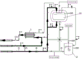
As shown in fig. 1, a hydrogen storage type hydrogen refueling station according to the present invention includes: the liquid hydrogen unloading skid 200 with the submerged pump pool, the liquid hydrogen storage tank group 100 consisting of at least one fixed liquid hydrogen storage tank, the liquid hydrogen and high-pressure hydrogen mixed hydrogenation skid 300 and the BOG recycling skid 400, wherein the liquid hydrogen and high-pressure hydrogen mixed hydrogenation skid 300 consists of a liquid hydrogen hydrogenation skid 301 and a high-pressure hydrogen hydrogenation skid 302.
Liquid hydrogen hydrogenation sled 301 include: a liquid hydrogen hydrogenation machine 303; the high pressure hydrogen pry 302 includes: a buffer solution hydrogen tank 304, a low-temperature plunger pump group 305, a gasifier group 306, a sequence control disc 307, a gas storage tank group 308 and a high-pressure hydrogen hydrogenation machine 309; BOG recycle sled 400 include: a BOG cache tank 401 and a BOG compressor 402.
A liquid inlet of the liquid hydrogen unloading pry 200 with the submerged pump pool is connected with a liquid outlet of liquid hydrogen source equipment, a first liquid hydrogen outlet of the liquid hydrogen unloading pry 200 with the submerged pump pool is connected with a general liquid inlet of the liquid hydrogen storage tank group 100, and a second liquid hydrogen outlet of the liquid hydrogen unloading pry 200 with the submerged pump pool is connected with an inlet of a liquid hydrogen hydrogenation machine through a first liquid hydrogen output pipeline 522; the total liquid outlet of the liquid hydrogen storage tank group 100 is connected with the liquid inlet of the buffer liquid hydrogen tank 304 through a second liquid hydrogen output pipeline 512, the liquid outlet of the buffer liquid hydrogen tank 304 is connected with the inlet of the low-temperature plunger pump group 305 through a third liquid hydrogen output pipeline 5, the outlet of the low-temperature plunger pump group 305 is sequentially connected with the gas inlets of the gasifier group 306, the sequence control disc 307 and the gas storage tank group 308 through a first hydrogen output pipeline 83, and the gas outlet of the gas storage tank group 308 is sequentially connected with the inlet of the sequence control disc 307 and the high-pressure hydrogen hydrogenation machine 309 through a second hydrogen output pipeline 84.
When liquid hydrogen is filled, liquid hydrogen in the liquid hydrogen storage tank group 100 or the liquid hydrogen source equipment 500 is conveyed to the liquid hydrogen hydrogenation machine through an immersed pump in an immersed pump pool to realize liquid hydrogen filling.
When the system is in operation, liquid hydrogen in the liquid hydrogen storage tank group 100 enters the low-temperature plunger pump group 305 through the buffer liquid hydrogen tank under the action of pressure difference, then is pressurized by the low-temperature plunger pump group 305 to form high-pressure hydrogen, the high-pressure hydrogen is gasified by the gasifier group 306, and the gasified high-pressure hydrogen enters each gas storage tank of the gas storage tank group 308 to be stored under the regulation of the sequence control disc 307. When the high-pressure hydrogen is filled, the high-pressure hydrogen in the gas storage tank group 308 is conveyed to the high-pressure hydrogen hydrogenation machine through the sequence control disc 307, so that the high-pressure hydrogen is filled.
In actual operation, a plurality of high-pressure hydrogen hydrogenation machines 309 may be provided, and the filling pressures of the high-pressure hydrogen hydrogenation machines may not be completely the same, for example, a plurality of 70MPa high-pressure hydrogen hydrogenation machines and a plurality of 35MPa high-pressure hydrogen hydrogenation machines are provided, and usually the gas storage tank group 308 is also composed of a plurality of gas storage tanks with different pressures, so as to meet the use requirements of the high-pressure hydrogen hydrogenation machines with different filling pressures.
The gas outlet of liquid hydrogen source equipment, the total gas outlet of liquid hydrogen storage tank group 100, the gas outlet of liquid hydrogen unloading sled 200, the gas outlet of liquid hydrogen hydrogenation machine 303 and the gas outlet of buffer solution hydrogen tank 304 are respectively collected and connected to the gas inlet of BOG cache tank 401 through corresponding first BOG gas pipeline 8, the gas outlet of BOG cache tank 401 is connected with the gas inlet of BOG compressor 402 through second BOG gas pipeline 81, and the gas outlet of BOG compressor 402 is connected to first output hydrogen pipeline 83 between gasifier group 306 and sequence control panel 307 through third output hydrogen pipeline 82. The BOG hydrogen generated in the operation process or the shutdown state of the liquid hydrogen source equipment, namely the liquid hydrogen storage tank group 100, the liquid hydrogen unloading skid 200, the liquid hydrogen hydrogenation machine 303, the buffer hydrogen tank 304 and the liquid hydrogen source equipment, is collected in the BOG cache tank 401, the pressure in the BOG cache tank 401 is increased along with the increase of the hydrogen amount collected in the BOG cache tank 401, the BOG compressor 402 is started when the pressure in the BOG cache tank 401 reaches a set value, and the high-pressure hydrogen is pumped into the sequence control panel 307 through the BOG compressor 402 and then stored in each gas storage tank of the gas storage tank group 308. Here, the pressure in the BOG cache tank 401 can be measured by arranging a pressure detection instrument, and the signal output end of the pressure detection instrument and the BOG compressor 402 can be connected with a control system, and the control system can judge and control whether the BOG compressor 402 is started or not according to the signal output by the pressure detection instrument.
In order to ensure that each pipeline for transporting liquid hydrogen has good heat insulation performance and avoid heat absorption and gasification of liquid hydrogen as much as possible, the first output liquid hydrogen pipeline 522, the second output liquid hydrogen pipeline 512 and the third output liquid hydrogen pipeline 5 in this embodiment all adopt vacuum jacket heat insulation pipes, each vacuum jacket heat insulation pipe is composed of an inner pipe and an outer pipe which are coaxial, and a vacuumizing interlayer is arranged between the inner pipe and the outer pipe.
The liquid hydrogen source equipment can be a liquid hydrogen tank car 500, and can also be a liquid hydrogen ship, a liquid hydrogen train, a liquid hydrogen pipeline and the like. In this embodiment, a liquid hydrogen tank car is taken as an example of the liquid hydrogen source device. Liquid hydrogen is used as a hydrogen source, so that the hydrogen storage capacity and the hydrogenation scale of the hydrogenation station are greatly enlarged, and the hydrogen cost is reduced; meanwhile, liquid hydrogen is used as a hydrogen source, the limitation of the filling temperature rise of the vehicle-mounted hydrogen storage bottle is broken through, the filling efficiency and the filling amount are improved by improving the filling speed, and particularly excellent user experience is brought to a fuel cell automobile user with long endurance mileage. Meanwhile, liquid hydrogen is used as a hydrogen source, the purity of the liquid hydrogen can be ensured to be more than 99.999%, when the liquid hydrogen is reused, the purity can be improved to 99.9999-99.99999%, hydrogen fuel meeting the requirements can be provided for a hydrogen fuel cell automobile, and the service life of the hydrogen fuel cell automobile is prolonged.
The hydrogen storage type hydrogen filling station covers the hydrogenation requirements of all hydrogen fuel cell automobile users, including liquid hydrogen filling, 70MPa high-pressure hydrogen filling and 35MPa high-pressure hydrogen filling. In addition, liquid hydrogen filling or deep cooling high-pressure filling is carried out, the temperature of the hydrogen fuel is about-253 to-233 ℃, and the limitation that the temperature rise of a vehicle-mounted hydrogen storage bottle exceeds the maximum service temperature of 85 ℃ caused by the over-high hydrogenation speed in the original high-pressure hydrogen filling process can be avoided. Therefore, the filling efficiency can be improved by improving the filling speed, and the filling experience similar to that of a fuel vehicle is achieved.
Example two
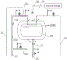
The embodiment is based on the embodiment one, and further perfects the specific layout structure of the liquid hydrogen unloading pry. As shown in fig. 2, the liquid hydrogen unloading skid described in this embodiment includes: the device comprises a supercharger 3, an immersed pump pool 2 with an immersed pump 20, a four-way valve 4, a plurality of liquid hydrogen pipelines, a plurality of hydrogen pipelines and a plurality of valves.
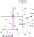
Referring to fig. 4, the liquid hydrogen storage tank group 100 has five connection ports, namely a total liquid inlet b, a total liquid outlet a, a first total gas port c, a second total gas port d and a third total gas port e. The fixed liquid hydrogen storage tank in the embodiment is a vacuum heat insulation storage tank, the vacuum heat insulation storage tank is one of a vertical storage tank and a horizontal storage tank, and the vacuum heat insulation storage tank is one of an overground storage tank and a buried storage tank. When the number of the fixed liquid hydrogen storage tanks is two or more, the fixed liquid hydrogen storage tanks are arranged in parallel, each fixed liquid hydrogen storage tank is provided with five connecting ports, namely a liquid inlet, a liquid outlet, a first gas port, a second gas port and a third gas port, the liquid inlets of the fixed liquid hydrogen storage tanks are connected in parallel to form a total liquid inlet b, the liquid outlets of the fixed liquid hydrogen storage tanks are connected in parallel to form a total liquid outlet a, the first gas ports of the fixed liquid hydrogen storage tanks are connected in parallel to form a first total gas port c, the second gas ports of the fixed liquid hydrogen storage tanks are connected in parallel to form a second total gas port d, and the third gas ports of the fixed liquid hydrogen storage tanks are connected in parallel to form a third total gas port e. The present embodiment is illustrated by taking as an example the case where the number of the fixed type liquid hydrogen tanks is set to one.
As shown in fig. 5, the immersed pump pool 2 has three connectors, namely a pump pool inlet 21, an immersed pump outlet 22 and a pump pool outlet 23. The four-way valve 4 is provided with four connecting ports, namely a first opening f, a second opening g, a third opening j and a fourth opening i. As shown in fig. 3, the supercharger 3 includes three connection ports, i.e., a first connection port 31, a second connection port 32, and a third connection port 33. The supercharger 3 described in this embodiment adopts a spiral fin-tube type air heat exchanger to increase the contact area with the ambient air, and uses the ambient air to heat the liquid hydrogen in the fin tubes to gasify the liquid hydrogen, so that the pressure of the liquid hydrogen tank car 500 or the fixed liquid hydrogen storage tank group 100 is adjusted by using the hydrogen to ensure the normal operation of the system.
As shown in fig. 2, the plurality of liquid hydrogen pipes includes: a first liquid hydrogen pipe 51, a second liquid hydrogen pipe 52, a third liquid hydrogen pipe 53, a fourth liquid hydrogen pipe 54, a fifth liquid hydrogen pipe 55, a first liquid hydrogen branch pipe 511, a second liquid hydrogen branch pipe 531, a third liquid hydrogen branch pipe 532, a fourth liquid hydrogen branch pipe 533, a fifth liquid hydrogen branch pipe 541, and a sixth liquid hydrogen branch pipe 542. In order to ensure that each liquid hydrogen pipeline has good heat insulation performance and avoid heat absorption and gasification of the liquid hydrogen as much as possible, the liquid hydrogen pipeline in the embodiment adopts a vacuum jacket heat insulation pipe, the vacuum jacket heat insulation pipe is composed of an inner pipe and an outer pipe which are coaxial, and a vacuumizing interlayer is arranged between the inner pipe and the outer pipe.
The plurality of hydrogen gas conduits include: a first hydrogen gas conduit 56, a second hydrogen gas conduit 57, and a third hydrogen gas conduit 58. The plurality of valves includes: the first valve 71, the second valve 72, the third valve 73, the fourth valve 74, the fifth valve 75, the sixth valve 76, the seventh valve 77, the eighth valve 78, the ninth valve 79, the tenth valve 710, the eleventh valve 711, and the twelfth valve 712.
As shown in fig. 2, 3 and 5, an unloading port joint 61 capable of being in sealed butt joint with a discharge port of the liquid hydrogen tanker 500 is fixedly arranged at one end of the first liquid hydrogen pipeline 51, and the other end of the first liquid hydrogen pipeline 51 is in sealed communication with the pump tank inlet 21 of the submerged pump tank 2. The unloading port joint 61 adopts a joint formed by a liquid hydrogen breaking valve and a liquid hydrogen hose, and the liquid hydrogen breaking valve belongs to a relatively mature valve element in a liquid hydrogen industrial chain. A first valve 71 and a second valve 72 are sequentially arranged on the first liquid hydrogen pipeline 51 from the end of the unloading port joint 61 to the other end at intervals, a first liquid hydrogen branch pipeline 511 is arranged on the first liquid hydrogen pipeline 51 between the second valve 72 and the pump tank liquid inlet 21 of the immersed pump tank 2, and the first liquid hydrogen branch pipeline 511 is in sealed communication with a first opening f of the four-way valve 4. One end of the second output liquid hydrogen pipeline 512 is connected to a first through hole 513 on the side wall of the first liquid hydrogen pipeline 51 between the second valve 72 and the liquid inlet 21 of the pump pool of the immersed pump pool 2, and the other end of the second output liquid hydrogen pipeline 512 is connected to the liquid inlet of the buffer liquid hydrogen tank 304.
As shown in fig. 2 and 5, one end of the second liquid hydrogen pipe 52 is in sealed communication with the immersed pump outlet 22 of the immersed pump tank 2, and the other end of the second liquid hydrogen pipe 52 is in sealed communication with the second opening g of the four-way valve 4. One end of the first output liquid hydrogen pipeline 522 is connected to the second through hole 521 on the side wall of the second liquid hydrogen pipeline 52, and the other end of the first output liquid hydrogen pipeline 522 is connected to the inlet of the liquid hydrogen hydrogenation machine 303.
As shown in fig. 2, 3 and 4, one end of the third liquid hydrogen pipe 53 is connected to the third through hole 510 of the sidewall of the first liquid hydrogen pipe between the first valve 71 and the second valve 72 in a sealing manner, and the other end of the third liquid hydrogen pipe 53 forms a two-way branch: the second liquid hydrogen branch pipe 531 is in sealed communication with the total liquid inlet b of the liquid hydrogen storage tank group 100, and the third liquid hydrogen branch pipe 532 is in sealed communication with the first total gas port c of the liquid hydrogen storage tank group 100. A twelfth valve 712 is provided in the third liquid hydrogen branch pipe 532. A third valve 73 and a fourth valve 74 are sequentially provided on the third liquid hydrogen pipe 53 at an interval from the end connected to the third through hole 510 of the side wall of the first liquid hydrogen pipe to the other end, a fourth liquid hydrogen branch pipe 533 is provided on the third liquid hydrogen pipe 53 between the third valve 73 and the fourth valve 74, and the fourth liquid hydrogen branch pipe 533 is in sealed communication with the fourth opening i of the four-way valve 4.
As shown in fig. 2 and 3, a pressurizing port joint 62 capable of being in sealed butt joint with a pressurizing port of a liquid hydrogen tank truck 500 is fixedly arranged at one end of the fourth liquid hydrogen pipeline 54, and the other end of the fourth liquid hydrogen pipeline 54 forms a two-way branch: a fifth liquid hydrogen branch pipe 541 and a sixth liquid hydrogen branch pipe 542, wherein the fifth liquid hydrogen branch pipe 541 is in sealed communication with the first connection port 31 of the supercharger 3, and the sixth liquid hydrogen branch pipe 542 is in sealed connection with the fourth through hole 530 on the side wall of the third liquid hydrogen pipe between the third valve 73 and the fourth valve 74. The fourth liquid hydrogen pipe 54 is provided with a fifth valve 75, the fifth liquid hydrogen branch pipe 541 is provided with a sixth valve 76, and the sixth liquid hydrogen branch pipe 542 is provided with a seventh valve 77. The pressurizing port joint 62 is a joint formed by a liquid hydrogen breaking valve and a liquid hydrogen hose.
As shown in fig. 2 and 4, one end of the fifth liquid hydrogen pipeline 55 is in sealed communication with the main liquid outlet a of the liquid hydrogen storage tank group 100, the other end of the fifth liquid hydrogen pipeline 55 is in sealed communication with the third opening j of the four-way valve 4, and the fifth liquid hydrogen pipeline 55 is provided with an eighth valve 78.
As shown in fig. 2 and 3, a gas phase port joint 63 capable of being in sealed butt joint with a gas phase port of the liquid hydrogen tank wagon 500 is fixedly arranged at one end of the first hydrogen pipeline 56, the other end of the first hydrogen pipeline 56 is in sealed communication with the third connecting port 33 of the supercharger 3, and a ninth valve 79 is arranged on the first hydrogen pipeline 56. The gas phase port joint 63 is a joint formed by a hydrogen breaking valve and a hydrogen hose.
As shown in fig. 2, 3 and 4, one end of the second hydrogen pipe 57 is in sealed communication with the second connection port 32 of the supercharger 3, the other end of the second hydrogen pipe 57 is in sealed connection with the fifth through hole 534 of the side wall of the sixth liquid hydrogen branch pipe between the twelfth valve 712 and the first total gas port c, and the tenth valve 710 is provided in the second hydrogen pipe 57.
As shown in fig. 2, 4 and 5, one end of the third hydrogen pipeline 58 is in sealed communication with the pump pool air outlet 23 of the immersed pump pool 2, and the other end of the third hydrogen pipeline 58 is in sealed communication with the third main air port e of the liquid hydrogen storage tank group 100.
As shown in fig. 2 and 4, the second total gas port d of the liquid hydrogen storage tank group 100 is connected to the gas inlet of the BOG cache tank 401 through the corresponding first BOG gas pipe 8, and an eleventh valve 711 is provided on the first BOG gas pipe 8 corresponding to the second total gas port d of the liquid hydrogen storage tank group 100.
And each liquid hydrogen pipeline and each hydrogen pipeline are respectively provided with a safety valve bank consisting of an overpressure safety release port and a safety valve, and detection instruments such as a temperature sensor and a pressure sensor, wherein the release ports of the safety valve bank are communicated with an air inlet of a BOG cache tank in the BOG recycling pry. Each safety valve group, each temperature sensor and each pressure sensor are connected with a control system with an alarm device; when the pressure in any liquid hydrogen pipeline or any hydrogen pipeline exceeds the set pressure of the control system, the control system starts the alarm device and starts the safety valve group on the corresponding liquid hydrogen pipeline to release the pressure.
Each valve can adopt an electric regulating valve or a pneumatic regulating valve and is respectively connected with a control system; when unloading, the control system can control each valve, thereby realizing one of three unloading modes of unloading of the immersed pump, self-pressurization unloading and combined unloading of the supercharger and the immersed pump; when each fixed liquid hydrogen storage tank is pressurized, the control system can control each valve according to the pressure value and the temperature value in each liquid hydrogen pipeline and each hydrogen pipeline, so that one of two pressure regulating modes of self-pressurization pressure regulation and pressure regulation by combining a supercharger and an immersed pump is realized. The electrical equipment and the instrument equipment adopt explosion-proof electrical equipment and instrument equipment suitable for liquid hydrogen. Flow meters may be optionally provided in the respective liquid hydrogen pipes and the respective hydrogen pipes, and as shown in fig. 2, a flow meter may be provided in the first liquid hydrogen pipe 51.
After the liquid hydrogen tanker 500 is transported to the hydrogen storage type hydrogen filling station, the discharge opening of the liquid hydrogen tanker 500 is in sealed butt joint with the unloading opening joint 61, the pressurization opening of the liquid hydrogen tanker 500 is in sealed butt joint with the pressurization opening joint 62, and the gas phase opening of the liquid hydrogen tanker 500 is in sealed butt joint with the gas phase opening joint 63.
When the indoor temperature is higher, the unloading is preferably carried out by adopting a self-pressurization unloading mode. When the self-pressurization unloading mode is adopted for unloading, as shown in fig. 6, the first valve 71, the third valve 73, the fourth valve 74, the fifth valve 75, the sixth valve 76, the ninth valve 79 and the twelfth valve 712 are opened, and the second valve 72, the seventh valve 77, the eighth valve 78, the tenth valve 710 and the eleventh valve 711 are closed.
Liquid hydrogen in the liquid hydrogen tank car 500 flows into the supercharger 3 through the supercharging port, the supercharging port joint 62, the fourth liquid hydrogen pipeline 54, the fifth liquid hydrogen branch pipeline 541 and the first connecting port 31 of the supercharger 3, and returns to the upper part of the liquid hydrogen tank car 500 through the third connecting port 33 of the supercharger 3, the first hydrogen pipeline 56, the gas phase port joint 63 and the gas phase port of the liquid hydrogen tank car 500 after being heated and gasified by ambient air so as to increase the internal pressure of the liquid hydrogen tank car. Then liquid hydrogen in the liquid hydrogen tank wagon utilizes the pressure difference between the liquid hydrogen tank wagon 500 and the liquid hydrogen storage tank group 1, and is shunted after passing through a discharge opening of the liquid hydrogen tank wagon 500, a discharge opening joint 61, a first liquid hydrogen pipeline 51 and a third liquid hydrogen pipeline 53: the liquid hydrogen flows into each fixed liquid hydrogen storage tank for storage through the second liquid hydrogen branch pipe 531 and the total liquid inlet b of the liquid hydrogen storage tank group 100, and the gasified gas in the liquid hydrogen flows into the gas phase space at the upper part of each fixed liquid hydrogen storage tank through the third liquid hydrogen branch pipe 532 and the first total gas inlet c of the liquid hydrogen storage tank group 100. And realizing quick unloading. With the increase of the liquid in the fixed liquid hydrogen storage tank, the gas phase pressure in the fixed liquid hydrogen storage tank becomes higher, and when the pressure exceeds the design pressure, the eleventh valve 711 needs to be opened to release the pressure. The self-pressurization unloading mode has the advantage of no energy consumption.
When the indoor temperature is lower, two modes of unloading by the immersed pump and unloading by combining the supercharger and the immersed pump are adopted, and the unloading speed of the supercharger and the immersed pump is higher and the time consumption is less than that of the unloading by the immersed pump.
When the immersed pump unloading mode is adopted for unloading, whether the immersed pump in the immersed pump pool 2 is in a standby state or not is firstly confirmed, and if the immersed pump is not in the standby state, precooling is needed in advance to ensure that the immersed pump 20 can normally work. After confirming that the immersed pump 20 can normally operate, as shown in fig. 7, the first valve 71, the second valve 72, the fourth valve 74, the ninth valve 79 and the tenth valve 710 are opened, the fourth opening i of the four-way valve is communicated with the second opening g, the third opening j is not communicated with the first opening f, and the third valve 73, the fifth valve 75, the sixth valve 76, the seventh valve 77, the eighth valve 78, the eleventh valve 711 and the twelfth valve 712 are closed.
Liquid hydrogen in the liquid hydrogen tank wagon 500 flows into the immersed pump pool 2 through a discharge opening of the liquid hydrogen tank wagon 500, a wagon unloading opening joint 61, a first liquid hydrogen pipeline 51 and a pump pool liquid inlet 21 of the immersed pump pool 2 by utilizing the pressure difference between the liquid hydrogen tank wagon and the immersed pump pool, the liquid hydrogen is pumped out from an immersed pump liquid outlet 22 of the immersed pump pool 2 through the immersed pump 20, and the pumped liquid hydrogen flows into each fixed liquid hydrogen storage tank for storage through a second liquid hydrogen pipeline 52, a four-way valve 4, a fourth liquid hydrogen branch pipeline 533, a third liquid hydrogen pipeline 53, a second liquid hydrogen branch pipeline 531 and a total liquid inlet b of the liquid hydrogen storage tank group 1. Along with the increase of the liquid in the fixed liquid hydrogen storage tank, the gas phase pressure in the fixed liquid hydrogen storage tank is increased, the hydrogen in the fixed liquid hydrogen storage tank flows into the supercharger 3 through the first main gas port c, the third liquid hydrogen branch pipe 532, the second hydrogen pipe 57 and the second connecting port 32 of the liquid hydrogen storage tank group 100, and returns to the upper part of the liquid hydrogen tank wagon 500 through the third connecting port 33 of the supercharger 3, the first hydrogen pipe 56, the gas phase port joint 63 and the gas phase port of the liquid hydrogen tank wagon 500 after being heated and gasified by ambient air, so as to increase the internal pressure of the liquid hydrogen tank wagon. The problem of the gaseous phase pressure reduction that liquid hydrogen tank wagon caused because of the liquid phase reduces has been solved on the one hand like this, and the fixed liquid hydrogen storage tank causes gaseous phase pressure to rise because of the liquid increases on the other hand. Therefore, the fixed liquid hydrogen storage tank does not need to be decompressed in the whole unloading process. The submerged pump unloading mode has the advantages that the fixed liquid hydrogen storage tank is not required to be decompressed, and liquid hydrogen is not consumed.
When the booster and the immersed pump are used for unloading in a combined unloading mode, whether the immersed pump in the immersed pump pool 2 is in a standby state or not is firstly confirmed, and if the immersed pump is not in the standby state, precooling is needed in advance to ensure that the immersed pump 20 can normally work. After confirming that the immersed pump 20 can normally operate, as shown in fig. 8, the first valve 71, the second valve 72, the fourth valve 74, and the twelfth valve 712 are opened, the fourth opening i of the four-way valve 4 is communicated with the second opening g, the third opening j is not communicated with the first opening f, and the third valve 73, the fifth valve 75, the sixth valve 76, the ninth valve 79, the seventh valve 77, the eighth valve 78, the ninth valve 79, the tenth valve 710, and the eleventh valve 711 are closed.
Liquid hydrogen in the liquid hydrogen tank wagon 500 utilizes the pressure difference between the liquid hydrogen tank wagon and the immersed pump pool 2, flows into the immersed pump pool 2 through the discharge opening of the liquid hydrogen tank wagon 500, the unloading opening joint 61, the first liquid hydrogen pipeline 51 and the pump pool inlet 21 of the immersed pump pool 2, and is pumped out from the immersed pump outlet 22 of the immersed pump pool 2 through the immersed pump 20, and the pumped liquid hydrogen is shunted after passing through the second liquid hydrogen pipeline 52, the fourth liquid hydrogen branch pipeline 533 and the third liquid hydrogen pipeline 53: the liquid hydrogen flows into each fixed liquid hydrogen storage tank for storage through the second liquid hydrogen branch pipe 531 and the total liquid inlet b of the liquid hydrogen storage tank group 100, and the gasified gas in the liquid hydrogen flows into the gas phase space at the upper part of each fixed liquid hydrogen storage tank through the third liquid hydrogen branch pipe 532 and the first total gas inlet c of the liquid hydrogen storage tank group 100.
As the liquid hydrogen in the liquid hydrogen tank car 500 becomes less and less, the gas phase pressure in the liquid hydrogen tank car 500 also becomes smaller, and when the pressure of the liquid hydrogen tank car 500 and the immersed pump tank 2 is smaller than a set value, the fifth valve 75, the sixth valve 76, and the ninth valve 79 are opened. A part of the liquid hydrogen in the liquid hydrogen tank car 500 flows into the supercharger 3 through the supercharging port, the supercharging port joint 62, the fourth liquid hydrogen pipeline 54, the fifth liquid hydrogen branch pipeline 541 and the first connecting port 31 of the supercharger 3, and returns to the upper part of the liquid hydrogen tank car 500 through the third connecting port 33 of the supercharger 3, the first hydrogen pipeline 56, the gas phase port joint 63 and the gas phase port of the liquid hydrogen tank car 500 after being heated and gasified by ambient air, so as to increase the internal pressure of the liquid hydrogen tank car and maintain the gas phase pressure of the liquid hydrogen tank car.
Meanwhile, along with the increase of liquid in the fixed liquid hydrogen storage tank, the gas phase pressure in the fixed liquid hydrogen storage tank is increased, and in order to ensure the safety use performance of the fixed liquid hydrogen storage tank set 1, the eleventh valve 711 is required to be opened for pressure relief when the pressure exceeds the design pressure. The unloading mode combining the booster and the immersed pump has the advantages of high boosting speed and high unloading speed of the liquid hydrogen tank car.
When the hydrogen storage type hydrogen station normally works, the third opening j and the first opening f of the four-way valve are communicated, liquid hydrogen in the fixed liquid hydrogen storage tank flows into the submerged pump pool through the four-way valve 4 under the action of pressure difference and then flows into the liquid hydrogen hydrogenation pry, or liquid hydrogen in the fixed liquid hydrogen storage tank flows into the high-pressure hydrogen hydrogenation pry through the four-way valve 4 under the action of pressure difference. Along with the reduction of liquid in the fixed liquid hydrogen storage tank, the gas phase pressure in the fixed liquid hydrogen storage tank becomes small, when the gas phase pressure in the fixed liquid hydrogen storage tank is less than or equal to the external pressure, the liquid hydrogen cannot be output, and the pressure is required to be adjusted according to the situation.
When the system is in the power-off working condition, the pressure is regulated by adopting a self-pressurization pressure regulating mode. As shown in fig. 10, the sixth valve 76, the seventh valve 77, the eighth valve 78, and the tenth valve 710 are opened, the fourth port i and the third port j of the four-way valve 4 are communicated, and the first valve 71, the second valve 72, the third valve 73, the fourth valve 74, the fifth valve 75, the ninth valve 79, the eleventh valve 711, and the twelfth valve 712 are closed.
Under the action of the pressure difference, the liquid hydrogen flows into the supercharger 3 from the total liquid outlet a of the liquid hydrogen storage tank group 100, the fifth liquid hydrogen pipeline 55, the four-way valve 4, the fourth liquid hydrogen branch pipeline 533, the third liquid hydrogen pipeline 53, the sixth liquid hydrogen branch pipeline 542, the fifth liquid hydrogen branch pipeline 541 and the first connecting port 31 of the supercharger 3, is heated and gasified by ambient air, and then enters the upper gas phase space of each fixed liquid hydrogen storage tank through the second connecting port 32 of the supercharger 3, the second hydrogen pipeline 57, the third liquid hydrogen branch pipeline 532 and the first total gas port c of the liquid hydrogen storage tank group 100 to pressurize each fixed liquid hydrogen storage tank. The self-boosting pressure regulating mode has the advantage of no energy consumption.
When the system is in a normal working condition, the pressure is regulated by preferentially adopting a mode of jointly regulating the pressure by a supercharger and an immersed pump in consideration of timeliness. As shown in fig. 9, the sixth valve 76, the seventh valve 77, the eighth valve 78, and the tenth valve 710 are opened, the third opening j of the four-way valve 4 is communicated with the first opening f, the fourth opening i is communicated with the second opening g, and the first valve 71, the second valve 72, the third valve 73, the fourth valve 74, the fifth valve 75, the ninth valve 79, the eleventh valve 711, and the twelfth valve 712 are closed.
Liquid hydrogen flows into the immersed pump pool 2 from the total liquid outlet a of the liquid hydrogen storage tank group 100, the fifth liquid hydrogen pipeline 55, the first liquid hydrogen pipeline 51 and the pump pool liquid inlet 21 of the immersed pump pool 2 under the action of pressure difference, the liquid hydrogen is pumped out from the immersed pump liquid outlet 22 of the immersed pump pool 2 through the immersed pump 20, the pumped liquid hydrogen flows into the supercharger 3 through the second liquid hydrogen pipeline 52, the four-way valve 4, the fourth liquid hydrogen branch pipeline 533, the third liquid hydrogen pipeline 53, the sixth liquid hydrogen branch pipeline 542, the fifth liquid hydrogen branch pipeline and the first connecting port 31 of the supercharger 3, and the liquid hydrogen is heated and gasified by ambient air and then enters the upper gas phase space of each fixed liquid hydrogen storage tank through the second connecting port 32 of the supercharger 3, the second hydrogen pipeline 57, the third liquid hydrogen branch pipeline 532 and the first total gas port c of the liquid hydrogen storage tank group 100 to pressurize each fixed liquid hydrogen storage tank. The pressure regulating mode combining the pressure regulator and the immersed pump has the advantages of high pressure regulating speed, short pressure regulating time and high pressure.
The above description is only a preferred embodiment of the present invention, and is not intended to limit the present invention in any way, but any modifications or equivalent variations made in accordance with the technical spirit of the present invention are within the scope of the present invention as claimed.
The invention has the beneficial effects that: liquid hydrogen is unloaded sled, liquid hydrogen hydrogenation sled, BOG recycle sled and high-pressure hydrogen hydrogenation sled become sled or several are integrated into an integrated sled alone, through carry out the customization production in the professional mill, it is complete reliable to ensure every sled dress ization module function, size uniformity, the outward appearance is succinct, the interface is accurate, construction and installation is convenient, shorten on-the-spot installation engineering time, and reduce the dependence to engineering construction condition and installer to the at utmost, reduce the influence of various external uncertain factors to key equipment performance, reduce the system deviation.