CN111365688B - Lamp holder for plugging LED lamp beads - Google Patents
Lamp holder for plugging LED lamp beads Download PDFInfo
- Publication number
- CN111365688B CN111365688B CN201811596892.0A CN201811596892A CN111365688B CN 111365688 B CN111365688 B CN 111365688B CN 201811596892 A CN201811596892 A CN 201811596892A CN 111365688 B CN111365688 B CN 111365688B
- Authority
- CN
- China
- Prior art keywords
- lamp
- led lamp
- fixedly connected
- lamp holder
- bead
- Prior art date
- Legal status (The legal status is an assumption and is not a legal conclusion. Google has not performed a legal analysis and makes no representation as to the accuracy of the status listed.)
- Active
Links
Images


Classifications
-
- F—MECHANICAL ENGINEERING; LIGHTING; HEATING; WEAPONS; BLASTING
- F21—LIGHTING
- F21V—FUNCTIONAL FEATURES OR DETAILS OF LIGHTING DEVICES OR SYSTEMS THEREOF; STRUCTURAL COMBINATIONS OF LIGHTING DEVICES WITH OTHER ARTICLES, NOT OTHERWISE PROVIDED FOR
- F21V19/00—Fastening of light sources or lamp holders
- F21V19/0005—Fastening of light sources or lamp holders of sources having contact pins, wires or blades, e.g. pinch sealed lamp
-
- F—MECHANICAL ENGINEERING; LIGHTING; HEATING; WEAPONS; BLASTING
- F21—LIGHTING
- F21V—FUNCTIONAL FEATURES OR DETAILS OF LIGHTING DEVICES OR SYSTEMS THEREOF; STRUCTURAL COMBINATIONS OF LIGHTING DEVICES WITH OTHER ARTICLES, NOT OTHERWISE PROVIDED FOR
- F21V19/00—Fastening of light sources or lamp holders
- F21V19/001—Fastening of light sources or lamp holders the light sources being semiconductors devices, e.g. LEDs
- F21V19/0015—Fastening arrangements intended to retain light sources
-
- F—MECHANICAL ENGINEERING; LIGHTING; HEATING; WEAPONS; BLASTING
- F21—LIGHTING
- F21V—FUNCTIONAL FEATURES OR DETAILS OF LIGHTING DEVICES OR SYSTEMS THEREOF; STRUCTURAL COMBINATIONS OF LIGHTING DEVICES WITH OTHER ARTICLES, NOT OTHERWISE PROVIDED FOR
- F21V19/00—Fastening of light sources or lamp holders
- F21V19/02—Fastening of light sources or lamp holders with provision for adjustment, e.g. for focusing
-
- F—MECHANICAL ENGINEERING; LIGHTING; HEATING; WEAPONS; BLASTING
- F21—LIGHTING
- F21Y—INDEXING SCHEME ASSOCIATED WITH SUBCLASSES F21K, F21L, F21S and F21V, RELATING TO THE FORM OR THE KIND OF THE LIGHT SOURCES OR OF THE COLOUR OF THE LIGHT EMITTED
- F21Y2115/00—Light-generating elements of semiconductor light sources
- F21Y2115/10—Light-emitting diodes [LED]
Abstract
The invention discloses a lamp holder for plugging LED lamp beads, which comprises a lamp holder, supporting plates, a rotating seat and LED lamp beads, wherein the side wall of the lamp holder is provided with a circular hole, the inner wall of the circular hole is fixedly connected with a fastening plate, a clamping rotating rod is clamped inside the fastening plate, one side, far away from the lamp holder, of the clamping rotating rod is fixedly connected with three supporting plates, a flexible compression block is fixedly connected between the three supporting plates, the upper end surface of the lamp holder is provided with a plugging groove, and the rotating seat is connected in the plugging groove in a penetrating manner. This kind of lamp stand is used in LED lamp pearl grafting adopts the joint bull stick to combine together with the mounting plate for deformation takes place for flexible compression piece, thereby has realized buckling to the lamp stand, makes this kind of lamp stand is used in LED lamp pearl grafting be convenient for fix in the region of unevenness, adopts flexible rubber tube and insulating film to combine together, thereby the effectual waterproof protection against electric shock effect that reaches, and then has increased the security that the lamp stand used.
Description
Technical Field
The invention relates to the field of lighting devices, in particular to a lamp holder for plugging an LED lamp bead.
Background
The LED lamp bead is a light-emitting diode with a plug connector and can be directly plugged on a lamp holder, and is made of a semiconductor material so as to directly convert electric energy into light energy and convert an electric signal into an optical signal; the LED lamp has the advantages of low power consumption, high brightness, bright color, vibration resistance, long service life, cold light source and the like, is real green illumination, is widely applied to the decoration field and indicator lamps, and can be fixed by the lamp holder for plugging the LED lamp beads and provide power for the LED lamp beads.
However, the existing lamp holder for inserting the LED lamp beads cannot be bent and adjusted in angle, so that the lamp holder cannot adapt to installation surfaces in various shapes, and is easy to generate electric shock phenomenon in the inserting process, and the use safety is low, so that a novel lamp holder for inserting the LED lamp beads is needed to solve the problems.
Disclosure of Invention
Aiming at the defects in the prior art, the invention aims to provide the lamp holder for plugging the LED lamp beads, the lamp holder for plugging the LED lamp beads is combined with the fastening plate by adopting the clamping rotating rod, so that the flexible compression block is deformed, the lamp holder is bent, the lamp holder for plugging the LED lamp beads is convenient to fix in an uneven area, and the flexible rubber tube is combined with the insulating film, so that the waterproof and electric shock-proof effects are effectively achieved, and the use safety of the lamp holder is improved.
The technical purpose of the invention is realized by the following technical scheme: the utility model provides a lamp stand is used in grafting of LED lamp pearl, includes lamp stand, backup pad, rotates seat and LED lamp pearl, circular hole has been seted up to the lateral wall of lamp stand, the inner wall fixedly connected with mounting plate in circular hole, the inside joint of mounting plate has the joint bull stick, the joint bull stick is kept away from the three backup pad of one side fixedly connected with of lamp stand, it is three fixedly connected with flexible compression piece between the backup pad, the inserting groove has been seted up to the up end of lamp stand, through connection has the rotation seat in the inserting groove, the up end fixedly connected with plug post of rotation seat, it has LED lamp pearl to peg graft directly over the plug post.
Furthermore, a through hole is formed in one side, far away from the supporting plate, of the lamp holder, an external lead is connected to the inside of the through hole in a penetrating mode, and an insulating film wraps the outer wall of the external lead.
Furthermore, an insulating guide pipe penetrates through the lamp holder, a supporting plate penetrates through the insulating guide pipe, the insulating guide pipe is composed of a main line and three branch lines, and the three branch lines of the insulating guide pipe penetrate through the three insertion columns respectively.
Furthermore, the inner wall of the insertion column is fixedly connected with a conducting strip, the size of the outer wall of the conducting strip is equal to that of the inner wall of the insertion column, and the conducting strip is connected with the external lead.
Furthermore, the upper end face of the conducting strip is fixedly connected with a flexible rubber tube, the flexible rubber tube is collinear with the axis of the inserting column, the flexible rubber tube can be bent, and the flexible rubber tube is attached to the lower end face of the LED lamp bead.
Furthermore, the lower end face of each LED lamp bead is fixedly connected with two lamp bead connectors, the two lamp bead connectors are inserted into the insertion columns, and the lamp bead connectors are attached to the conductive sheet.
Furthermore, the outer wall of the lamp bead joint is sleeved with an insulating film, the upper end face of the insulating film is fixedly connected with the LED lamp beads, and the insulating film penetrates and is inserted into the flexible rubber cylinder.
In conclusion, the invention has the following beneficial effects:
1. this kind of lamp stand is used in LED lamp pearl grafting, in inserting the hole of lamp stand lateral wall through the joint bull stick, and make joint bull stick and the joint of fastening plate mutually, and through the rotation of joint bull stick, the axle center that the joint bull stick can be followed to the lamp stand has been realized and has been rotated, thereby the angle modulation to the lamp stand has been realized, and buckle through pulling two adjacent lamp stands and to flexible compression piece, make flexible compression piece take place the deformation, thereby the buckling to the lamp stand has been realized, make this kind of lamp stand is used in LED lamp pearl grafting can adapt to the installation face of various shapes.
2. This kind of lamp stand is used in grafting of LED lamp pearl adopts flexible rubber tube and insulating film to combine together, and when LED lamp pearl was pegged graft on the lamp stand, flexible rubber tube and insulating film closely laminated to effectual waterproof protection against electric shock effect that reaches has then increased the security that the lamp stand used.
Drawings
FIG. 1 is an overall block diagram of the present invention;
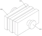
FIG. 2 is a view showing an overall structure of a lamp socket connection structure according to the present invention;
FIG. 3 is a cross-sectional view of the lamp socket of the present invention;
FIG. 4 is a cross-sectional view of the plug post of the present invention;
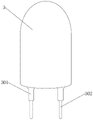
fig. 5 is an overall structure diagram of the LED lamp bead of the present invention.
In the figure, 1, a lamp holder; 101. connecting a lead externally; 102. a support plate; 103. a flexible compression block; 104. clamping the rotating rod; 105. a fastening plate; 106. an insulated conduit; 2. rotating the base; 201. inserting the columns; 202. a flexible rubber cylinder; 203. a conductive sheet; 3. LED lamp beads; 301. an insulating film; 302. the lamp pearl connects.
Detailed Description
The technical solutions in the embodiments of the present invention will be clearly and completely described below with reference to the drawings in the embodiments of the present invention, and it is obvious that the described embodiments are only a part of the embodiments of the present invention, and not all of the embodiments. All other embodiments, which can be obtained by a person skilled in the art without making any creative effort based on the embodiments in the present invention, belong to the protection scope of the present invention.
Example 1
Referring to fig. 1-5, a lamp stand is used in LED lamp pearl grafting, including lamp stand 1, backup pad 102, rotate seat 2 and LED lamp pearl 3, circular hole has been seted up to the lateral wall of lamp stand 1, the inner wall fixedly connected with mounting plate 105 in circular hole, the inside joint of mounting plate 105 has joint bull stick 104, the three backup pad 102 of one side fixedly connected with of lamp stand 1 is kept away from to joint bull stick 104, the flexible compression piece 103 of fixedly connected with between the three backup pad 102, the inserting groove has been seted up to the up end of lamp stand 1, through connection has in the inserting groove rotates seat 2, the up end fixedly connected with inserting column 201 of rotating seat 2, it has LED lamp pearl 3 to peg graft directly over inserting column 201. This kind of lamp stand is used in LED lamp pearl is pegged graft, insert the joint bull stick in the hole of lamp stand lateral wall, and make joint bull stick 104 and mounting plate 105 looks joint, realized linking together three lamp stand 1, and through the rotation of joint bull stick 104, realized that lamp stand 1 can follow the axle center of joint bull stick 104 and rotate, thereby realized the angle modulation to the lamp stand, buckle through pulling two adjacent lamp stands 1 and to flexible compression piece 103, make flexible compression piece 103 take place the deformation, thereby realized buckling to lamp stand 1, make the lamp stand can buckle at will and rotate, the installation face that this kind of lamp stand can adapt to various shapes for LED lamp pearl is pegged graft has been realized.
Example 2
Referring to fig. 1, 3 and 4, a through hole is formed in one side, away from a support plate 102, of a lamp holder 1, an external lead 101 penetrates through the inside of the through hole, an insulating film wraps the outer wall of the external lead 101, the insulating film plays a role in preventing the external lead 101 from being electrically leaked, an insulating guide tube 106 penetrates through the inside of the lamp holder 1, the support plate 102 penetrates through the inside of the insulating guide tube 106, the insulating guide tube 106 is composed of a main line and three branch lines, the three branch lines of the insulating guide tube 106 penetrate through three insertion columns 201 respectively, conducting strips 203 are fixedly connected to the inner walls of the insertion columns 201, the outer wall of the conducting strips 203 are equal to the inner wall of the insertion columns 201, the conducting strips 203 are connected with the external lead 101, after the external lead 101 is powered on, the external lead 101 penetrates through and is inserted into the insulating guide tube 106 and is connected with the conducting strips 203, and at this time, the LED lamp beads 3 are lightened.
Example 3
Referring to fig. 4 and 5, a lamp holder for plugging an LED lamp bead, an upper end surface of a conductive sheet 203 is fixedly connected with a flexible rubber tube 202, the flexible rubber tube 202 is collinear with an axis of a plugging column 201, the flexible rubber tube 202 can be bent, and the flexible rubber tube 202 is attached to a lower end surface of the LED lamp bead 3, the lower end surface of the LED lamp bead 3 is fixedly connected with two lamp bead connectors 302, the two lamp bead connectors 302 are plugged in the plugging column 201, and the lamp bead connectors 302 are attached to the conductive sheet 203, an insulating film 301 is sleeved on an outer wall of the lamp bead connectors 302, the upper end surface of the insulating film 301 is fixedly connected to the LED lamp bead 3, and the insulating film 301 is inserted into the flexible rubber tube 202 in a penetrating manner, the lamp bead connectors 302 are inserted into the plugging column 201, and the lamp bead connectors 302 are attached to the conductive sheet 203, then, the insulating film 302 is attached to an inner wall of the flexible rubber tube 202, and the lower end surface of the insulating film 302 is abutted to the upper end surface of the lamp bead column 201, thereby completing the plugging installation of the LED lamp bead 3.
The working principle is as follows: firstly, a lamp bead connector 302 is inserted into a plug column 201, the lamp bead connector 302 is attached to a conductive sheet 203, then an insulating film 302 is attached to the inner wall of a flexible rubber tube 202, the lower end face of the insulating film 302 is made to abut against the upper end face of the plug column 201, then a power supply is connected through an external lead 101, when the external lead 101 is powered on, the external lead 101 penetrates through and is inserted into an insulating guide tube 106 and is connected with the conductive sheet 203, at the moment, an LED lamp bead 3 is lightened, then a clamping rotating rod is inserted into a hole in the side wall of a lamp holder, the clamping rotating rod 104 is clamped with a fastening plate 105, three lamp holders 1 are connected together, then the lamp holders 1 can rotate along the axis of the clamping rotating rod 104 through rotation of the clamping rotating rod 104, so that the angle adjustment of the lamp holders is realized, then, two adjacent lamp holders 1 are pulled and the flexible compression blocks 103 are bent, so that the flexible compression blocks 103 are stably deformed, so that the lamp holders 1 can be bent and rotated at will be installed at will be bent and rotated freely, and finally, the lamp holders and the installation surfaces are adjusted according to the shapes of the lamp holders and the installation surfaces.
The present embodiment is only for explaining the present invention, and it is not limited to the present invention, and those skilled in the art can make modifications of the present embodiment without inventive contribution as needed after reading the present specification, but all of them are protected by patent law within the scope of the claims of the present invention.
Claims (7)
1. The utility model provides a lamp stand is used in grafting of LED lamp pearl, includes lamp stand (1), backup pad (102), rotates seat (2) and LED lamp pearl (3), its characterized in that: circular hole has been seted up to the lateral wall of lamp stand (1), the inner wall fixedly connected with mounting plate (105) in circular hole, the inside joint of mounting plate (105) has joint bull stick (104), joint bull stick (104) are kept away from three backup pad (102) of one side fixedly connected with of lamp stand (1), it is three fixedly connected with flexible compression piece (103) between backup pad (102), the inserting groove has been seted up to the up end of lamp stand (1), through connection has rotation seat (2) in the inserting groove, the up end fixedly connected with spliced pole (201) of rotating seat (2), it has LED lamp pearl (3) to peg graft directly over spliced pole (201).
2. The lamp holder for LED lamp bead plugging of claim 1, wherein: a through hole is formed in one side, far away from the supporting plate (102), of the lamp holder (1), an external lead (101) is connected to the inside of the through hole in a penetrating mode, and an insulating film wraps the outer wall of the external lead (101).
3. The lamp holder for LED lamp bead plugging of claim 2, wherein: the lamp holder is characterized in that an insulating guide pipe (106) penetrates through the lamp holder (1), the insulating guide pipe (106) penetrates through the supporting plate (102), the insulating guide pipe (106) is composed of a main line and three branch lines, and the three branch lines of the insulating guide pipe (106) penetrate through the three insertion columns (201) respectively.
4. The lamp holder for LED lamp bead plugging of claim 3, wherein: the inner wall of the inserting column (201) is fixedly connected with a conducting strip (203), the size of the outer wall of the conducting strip (203) is equal to that of the inner wall of the inserting column (201), and the conducting strip (203) is connected with the external lead (101).
5. The lamp holder is used in grafting of LED lamp pearl according to claim 4, characterized in that: the LED lamp is characterized in that the upper end face of the conducting strip (203) is fixedly connected with a flexible rubber tube (202), the flexible rubber tube (202) and the axis of the inserting column (201) are collinear, the flexible rubber tube (202) can be bent, and the flexible rubber tube (202) is attached to the lower end face of the LED lamp bead (3).
6. The LED lamp bead socket of claim 5, wherein: the LED lamp bead is characterized in that two bead connectors (302) are fixedly connected to the lower end face of the LED bead (3), the two bead connectors (302) are inserted into the insertion columns (201), and the bead connectors (302) are attached to the conducting strips (203).
7. The lamp holder for LED lamp bead plugging of claim 6, wherein: insulating film (301) is sleeved on the outer wall of the lamp bead joint (302), the upper end face of the insulating film (301) is fixedly connected with the LED lamp beads (3), and the insulating film (301) penetrates through and is inserted into the flexible rubber cylinder (202).
Priority Applications (1)
| Application Number | Priority Date | Filing Date | Title |
|---|---|---|---|
| CN201811596892.0A CN111365688B (en) | 2018-12-26 | 2018-12-26 | Lamp holder for plugging LED lamp beads |
Applications Claiming Priority (1)
| Application Number | Priority Date | Filing Date | Title |
|---|---|---|---|
| CN201811596892.0A CN111365688B (en) | 2018-12-26 | 2018-12-26 | Lamp holder for plugging LED lamp beads |
Publications (2)
| Publication Number | Publication Date |
|---|---|
| CN111365688A CN111365688A (en) | 2020-07-03 |
| CN111365688B true CN111365688B (en) | 2023-01-10 |
Family
ID=71206075
Family Applications (1)
| Application Number | Title | Priority Date | Filing Date |
|---|---|---|---|
| CN201811596892.0A Active CN111365688B (en) | 2018-12-26 | 2018-12-26 | Lamp holder for plugging LED lamp beads |
Country Status (1)
| Country | Link |
|---|---|
| CN (1) | CN111365688B (en) |
Citations (8)
| Publication number | Priority date | Publication date | Assignee | Title |
|---|---|---|---|---|
| CN1516862A (en) * | 2001-05-25 | 2004-07-28 | Illuminated signage employing light emitting diodes | |
| CN2746249Y (en) * | 2004-12-01 | 2005-12-14 | 樊邦弘 | Lighting structure on flexible PCB plate |
| CN201628145U (en) * | 2010-03-19 | 2010-11-10 | 林万炯 | LED spot lamp |
| CN201779528U (en) * | 2010-07-29 | 2011-03-30 | 张冰 | Christmas lamp string |
| CN204534202U (en) * | 2015-03-03 | 2015-08-05 | 朱衡 | A kind of can the combination lamp of bend fixing arbitrarily |
| CN206831227U (en) * | 2017-06-17 | 2018-01-02 | 江苏天际照明工程有限公司 | A kind of LED string |
| CN207661737U (en) * | 2017-12-21 | 2018-07-27 | 中山市虹宇光电科技有限公司 | A kind of not limit for length's series LED light bar driving power |
| CN108720193A (en) * | 2018-06-04 | 2018-11-02 | 郑州森源新能源科技有限公司 | A kind of buddhist bead-string |
Family Cites Families (1)
| Publication number | Priority date | Publication date | Assignee | Title |
|---|---|---|---|---|
| US7771109B2 (en) * | 2007-02-07 | 2010-08-10 | Jetmax Industrial Ltd. | Lamp for light string |
-
2018
- 2018-12-26 CN CN201811596892.0A patent/CN111365688B/en active Active
Patent Citations (8)
| Publication number | Priority date | Publication date | Assignee | Title |
|---|---|---|---|---|
| CN1516862A (en) * | 2001-05-25 | 2004-07-28 | Illuminated signage employing light emitting diodes | |
| CN2746249Y (en) * | 2004-12-01 | 2005-12-14 | 樊邦弘 | Lighting structure on flexible PCB plate |
| CN201628145U (en) * | 2010-03-19 | 2010-11-10 | 林万炯 | LED spot lamp |
| CN201779528U (en) * | 2010-07-29 | 2011-03-30 | 张冰 | Christmas lamp string |
| CN204534202U (en) * | 2015-03-03 | 2015-08-05 | 朱衡 | A kind of can the combination lamp of bend fixing arbitrarily |
| CN206831227U (en) * | 2017-06-17 | 2018-01-02 | 江苏天际照明工程有限公司 | A kind of LED string |
| CN207661737U (en) * | 2017-12-21 | 2018-07-27 | 中山市虹宇光电科技有限公司 | A kind of not limit for length's series LED light bar driving power |
| CN108720193A (en) * | 2018-06-04 | 2018-11-02 | 郑州森源新能源科技有限公司 | A kind of buddhist bead-string |
Also Published As
| Publication number | Publication date |
|---|---|
| CN111365688A (en) | 2020-07-03 |
Similar Documents
| Publication | Publication Date | Title |
|---|---|---|
| CN111365688B (en) | Lamp holder for plugging LED lamp beads | |
| CN212005217U (en) | Modular LED lamp plate structure | |
| CN204141309U (en) | A kind of LED | |
| CN207750753U (en) | A kind of equidistant formula slitless connection structure of line lamp | |
| CN204063771U (en) | A kind of LED freezer lamp | |
| CN215569886U (en) | Outdoor LED festival ornament lamp with light-operated function | |
| CN207112455U (en) | A kind of LED double-sides belts lens lamp bar | |
| US20220357026A1 (en) | Floor Lamp Capable Of Rotating By 360 Degrees | |
| CN204534224U (en) | A kind of Novel LED fluorescent lamp light fixture | |
| CN210088580U (en) | Ultrathin LED energy-saving bracket lamp with glass tube | |
| CN203162855U (en) | Lamp tube extension end covers and integrated LED bracket lamp tube lighting uniformly | |
| CN202501306U (en) | Ultra-thin panel lamp | |
| CN201811126U (en) | Novel solar lamp | |
| CN104141913A (en) | LED lamp | |
| CN209876556U (en) | Mounting structure of LED rotary stage lamp tube | |
| CN214038330U (en) | Luminous clamp | |
| CN204664968U (en) | Led fluorescent lamp tube | |
| CN204554726U (en) | A kind of new waterproof lamp socket | |
| CN202546449U (en) | Paster LED (Light Emitting Diode) flexible lamp strip | |
| CN204554478U (en) | The luminous aluminum strip module of a kind of LED | |
| CN211118848U (en) | Ultra-thin portable bar lamp | |
| CN210395764U (en) | Curtain wall unit body plate with night scene illuminating lamp | |
| CN202125780U (en) | Flexible SMD LED rainbow luminaire | |
| CN211083817U (en) | L ED underground lamp with good waterproof effect | |
| CN217635182U (en) | LED copper line lamp convenient to it is fixed |
Legal Events
| Date | Code | Title | Description |
|---|---|---|---|
| PB01 | Publication | ||
| PB01 | Publication | ||
| SE01 | Entry into force of request for substantive examination | ||
| SE01 | Entry into force of request for substantive examination | ||
| TA01 | Transfer of patent application right |
Effective date of registration: 20221108 Address after: No. 18-9, Xiangrong Road, Industrial Park, Taixing City, Taizhou, Jiangsu 225,300 Applicant after: Jiangsu Ningshi Electromechanical Technology Co.,Ltd. Address before: 350600 no.9-1, chezi village, sui'an Town, Zhangpu County, Zhangzhou City, Fujian Province Applicant before: Zhangpu Mingneng Photoelectric Technology Co.,Ltd. |
|
| TA01 | Transfer of patent application right | ||
| GR01 | Patent grant | ||
| GR01 | Patent grant |