CN111347757A - Offset printing UV printing ink automatic inking system - Google Patents
Offset printing UV printing ink automatic inking system Download PDFInfo
- Publication number
- CN111347757A CN111347757A CN202010318363.5A CN202010318363A CN111347757A CN 111347757 A CN111347757 A CN 111347757A CN 202010318363 A CN202010318363 A CN 202010318363A CN 111347757 A CN111347757 A CN 111347757A
- Authority
- CN
- China
- Prior art keywords
- ink
- container
- rod
- printing
- offset
- Prior art date
- Legal status (The legal status is an assumption and is not a legal conclusion. Google has not performed a legal analysis and makes no representation as to the accuracy of the status listed.)
- Pending
Links
- 238000007645 offset printing Methods 0.000 title claims abstract description 12
- 238000007639 printing Methods 0.000 title claims description 17
- 230000007246 mechanism Effects 0.000 claims abstract description 57
- 238000003756 stirring Methods 0.000 abstract description 9
- 238000009826 distribution Methods 0.000 abstract description 7
- 239000000976 ink Substances 0.000 description 146
- XLYOFNOQVPJJNP-UHFFFAOYSA-N water Substances O XLYOFNOQVPJJNP-UHFFFAOYSA-N 0.000 description 10
- 238000007599 discharging Methods 0.000 description 8
- 238000010586 diagram Methods 0.000 description 4
- 230000033001 locomotion Effects 0.000 description 4
- 230000000694 effects Effects 0.000 description 3
- 238000004519 manufacturing process Methods 0.000 description 3
- 238000005096 rolling process Methods 0.000 description 3
- 230000005540 biological transmission Effects 0.000 description 2
- 238000001035 drying Methods 0.000 description 2
- 238000000034 method Methods 0.000 description 2
- 230000009286 beneficial effect Effects 0.000 description 1
- 239000003638 chemical reducing agent Substances 0.000 description 1
- 238000004140 cleaning Methods 0.000 description 1
- 230000006835 compression Effects 0.000 description 1
- 238000007906 compression Methods 0.000 description 1
- 230000005484 gravity Effects 0.000 description 1
- 239000002904 solvent Substances 0.000 description 1
Images


Classifications
-
- B—PERFORMING OPERATIONS; TRANSPORTING
- B41—PRINTING; LINING MACHINES; TYPEWRITERS; STAMPS
- B41F—PRINTING MACHINES OR PRESSES
- B41F7/00—Rotary lithographic machines
- B41F7/02—Rotary lithographic machines for offset printing
-
- B—PERFORMING OPERATIONS; TRANSPORTING
- B41—PRINTING; LINING MACHINES; TYPEWRITERS; STAMPS
- B41F—PRINTING MACHINES OR PRESSES
- B41F31/00—Inking arrangements or devices
- B41F31/02—Ducts, containers, supply or metering devices
-
- B—PERFORMING OPERATIONS; TRANSPORTING
- B41—PRINTING; LINING MACHINES; TYPEWRITERS; STAMPS
- B41F—PRINTING MACHINES OR PRESSES
- B41F31/00—Inking arrangements or devices
- B41F31/02—Ducts, containers, supply or metering devices
- B41F31/03—Ink agitators
Landscapes
- Engineering & Computer Science (AREA)
- Mechanical Engineering (AREA)
- Inking, Control Or Cleaning Of Printing Machines (AREA)
Abstract
The invention provides an automatic offset printing UV ink feeding system which mainly comprises an ink container, an ink hopper groove and an ink homogenizing rod, wherein a cross beam is arranged above the ink hopper groove, a transverse moving mechanism is arranged in the cross beam, a supporting table is fixed above the transverse moving mechanism, the ink container is fixed on the supporting table, a rotating mechanism is further arranged on the supporting table and drives the ink homogenizing rod to rotate, an ink outlet is formed in the lower end of the ink container, and the ink outlet is close to the ink homogenizing rod, so that ink flows into the ink hopper groove along the ink homogenizing rod. Aiming at the viscous characteristic of the offset UV ink, the automatic ink distribution device utilizes automatic pressurization ink discharge and combines an ink distribution rod to automatically stir back and forth and rotate to distribute the ink, so that the ink in the ink hopper groove can be more uniform, the quality of a printed product is stable, the automation efficiency is high, and the labor cost can be saved.
Description
Technical Field
The invention relates to the technical field of offset printing and inking equipment, in particular to an automatic offset printing UV ink inking system.
Background
Offset UV ink has been generally used in offset printing because of its characteristics of fast drying speed, good printing effect, etc., and the offset UV ink contains no solvent, so it is viscous and like paste. In the normal production process, an operator needs to stir the ink in the ink hopper tank at intervals for the uniformity of the ink, and meanwhile, the influence of ultraviolet light in long-time light on the surface of the ink is also prevented.
At present, offset printing equipment is high-speed equipment, the production speed is high, if full-page printing is met, the required ink amount is large, ink needs to be continuously added into an ink fountain groove, when the ink fountain groove is just filled with ink, the ink amount in the ink fountain groove is large, the gravity is also large, the ink amount is large compared with the ordinary ink amount, the printing color is deep, and the offset printing equipment is unstable. Meanwhile, frequent stirring is required for operators to prevent the uppermost ink from drying, so that the labor intensity is high, and the printing quality is unstable.
Disclosure of Invention
The invention aims to provide an automatic ink feeding system for offset printing UV ink, which can realize automatic pressurization ink feeding, and can be used for carrying out ink distribution by combining the rotation and back-and-forth stirring of an ink distributing rod without manual operation, so that the efficiency is high, and the labor cost is saved.
In order to achieve the purpose, the invention adopts the following technical scheme:
the invention relates to an automatic offset printing UV ink feeding system which mainly comprises an ink container, an ink hopper groove and an ink distributing rod, wherein a cross beam is arranged above the ink hopper groove, a transverse moving mechanism is arranged in the cross beam, a supporting table is fixed above the transverse moving mechanism, the ink container is fixed on the supporting table, a rotating mechanism is further arranged on the supporting table, the rotating mechanism drives the ink distributing rod to rotate, the transverse moving mechanism drives the ink container and the ink distributing rod to move left and right back and forth to stir ink in the ink hopper groove, an ink outlet is formed in the lower end of the ink container, the ink outlet is close to the ink distributing rod, and the ink flows into the ink hopper groove along the ink distributing rod to achieve uniform ink discharging.
Furthermore, the transverse moving mechanism is linked with the rotating mechanism, namely, the transverse moving mechanism and the rotating mechanism can be linked in a rolling worm gear mode or a double-worm transmission mode.
Furthermore, the two sides of the ink fountain groove are provided with limiting mechanisms so as to meet the requirement of the ink fountain groove on the change of the ink discharging width range.
Further, the container cover is arranged above the ink container, the air faucet is arranged on the container cover and is filled with compressed air, pressure generated inside the ink container can be used for ink discharging, air pressure can be adjusted according to production requirements, and then ink discharging speed is adjusted.
The invention has the beneficial effects that:
1. the ink container has an air nozzle pressurization ink feeding function, can achieve the required ink feeding amount by adjusting air pressure, and has stable ink feeding amount and strong operability;
2. the ink container and the ink distributing rod move synchronously, ink can enter the ink hopper groove along the ink distributing rod, and the ink discharging is softer and more uniform;
3. the ink discharging range can be adjusted by combining the limiting mechanism of the ink hopper groove, the ink discharging is more uniform, and the operability is strong;
4. even pole can carry out the rotation at the in-process of making a round trip the translation, is different from the big vortex in center that the rotatory stirring of tradition caused, and the little vortex effect of portable that the stirring formed is better while the translation, can play more softly, the more comprehensive stirring effect of mobility to thick UV printing ink.
Description of the drawings:
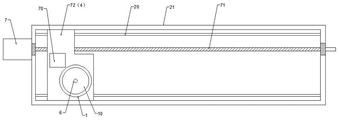
FIG. 1 is a schematic diagram of the overall structure of the present invention;
FIG. 2 is a schematic view of the non-related operation of the lateral moving mechanism and the rotating mechanism in the present invention;
FIG. 3 is a diagram showing the relationship between a lateral moving mechanism and a rotating mechanism using a rolling worm wheel;
FIG. 4 is a diagram showing the relationship between the lateral movement mechanism and the rotation mechanism in the present invention by using the twin worm drive;
FIG. 5 is a schematic view showing the structure of an ink container according to the present invention.
The specific implementation mode is as follows:
please refer to fig. 1, which is a schematic structural diagram of a preferred embodiment of the present invention, the present invention is an automatic ink-feeding system for offset printing UV ink, mainly including an ink container 1, an ink fountain 2 and an ink distribution rod 3, wherein a cross beam 21 is disposed above the ink fountain 2, a lateral moving mechanism is disposed in the cross beam 21, a support table 4 is fixed above the lateral moving mechanism, the ink container 1 is fixed on the support table 4, the lateral moving mechanism drives the ink container and the ink distribution rod to move back and forth left and right, a rotating mechanism is further disposed on the support table 4, the rotating mechanism drives the ink distribution rod 3 to rotate, so that the ink distribution rod 3 can move back and forth left and right in the ink fountain 2 to stir and rotate while translating, and a small movable vortex is formed, so that the ink in the ink fountain 2 is soft and uniform.
Specifically, the transverse moving mechanism and the rotating mechanism have three implementation modes, wherein one mode is that the transverse moving mechanism and the rotating mechanism respectively act and are not related to each other; the other two are the related action of the transverse moving mechanism and the rotating mechanism.
As shown in fig. 2, the lateral moving mechanism and the rotating mechanism respectively operate, specifically: the transverse moving mechanism comprises a screw rod 71 arranged on the cross beam 21 and a sliding block 72 linked with the screw rod 71, the screw rod 71 is driven by a first motor 7, two ends of the screw rod 71 are connected with the cross beam 21 through bearings, the support table 4 is fixed on the sliding block 72, or the sliding block 72 can directly replace the support table 4, in order to ensure the stable action of the sliding block 72, guide rails 20 can be arranged on two sides of the cross beam 21, two sides of the sliding block 72 are matched and linked with the guide rails 20, the screw rod 71 is driven by the first motor 7 to enable the sliding block 72 to horizontally move left and right, and therefore the ink container 1 and the ink evening rod; the rotating mechanism comprises a second motor 70, a driving shaft of the second motor 70 is connected with a sliding block 72 or a supporting table 4 through a bearing, the lower part of the driving shaft is directly connected with the ink homogenizing rod 3, or the second motor 70 is connected with the ink homogenizing rod 3 through a speed reducer, and the supporting table 4 or the sliding block 72 is provided with a proper hole position for the ink container 1 and the second motor 70 to be matched and assembled, so that the ink homogenizing rod 3 can rotate when the transverse moving mechanism drives the ink container 1 and the ink homogenizing rod 2 to do reciprocating translational motion.
The transverse moving mechanism and the rotating mechanism perform the associated actions specifically as follows:
(1) a worm wheel rolling mode, as shown in fig. 3, the transverse moving mechanism comprises a screw rod 71 arranged on the beam 21 and a slide block 72 linked with the screw rod 71, the screw rod 71 is driven by a first motor 7, two ends of the screw rod 71 are connected with the beam 21 through bearings, a support table 4 is fixed on the slide block 72, or the slide block 72 can directly replace the support table 4, in order to ensure the stable action of the slide block 72, guide rails 20 can be arranged on two sides of the beam 21, two sides of the slide block 72 are matched and linked with the guide rails 20, and the screw rod 71 is driven by the motor 7 to enable the slide block 72 to horizontally; the rotating mechanism comprises a worm wheel 91 connected with the sliding block 72 or the supporting table 4, the worm wheel 91 is connected with the sliding block 72 or the supporting table 4 through a bearing, the ink homogenizing rod 3 is connected below the worm wheel 91, the supporting table 4 or the sliding block 72 is provided with a proper hole position for fitting and assembling the ink container 1 and the worm wheel 91, one side of the cross beam 21 is connected with a worm 92 through the bearing, when the sliding block 72 and/or the supporting rod 4 drive the worm wheel 91 to do back-and-forth translation motion, the worm wheel 91 can be linked with the worm 92, namely the worm wheel 91 can rotate to drive the ink homogenizing rod 3 to;
(2) a double-worm transmission mode, as shown in fig. 4, the beam 21 is placed in an L shape, the lower part of the beam 21 should be hollowed, the lateral moving mechanism includes a first worm 81 installed on one side of the beam 21, a guide rail 20 installed on the beam 21 is provided above and below the first worm 81, the upper and lower ends of the slider 72 are engaged and linked with the guide rail 20, a first motor 7 is provided above the slider 72, a second worm 82 is provided in the middle of the slider 72, the upper and lower ends of the second worm 82 are engaged and connected with a bearing, the upper shaft end of the second worm 82 is connected with the first motor 7 or a speed reducing mechanism of the first motor 7, and the lower shaft end of the second worm 82 is connected with the ink distributing rod 3; the first worm 81 and the second worm 82 are perpendicular to each other, the threads are the same, the lead angle of the worm threads is 45 degrees, when the first motor 7 drives the second worm 82 to rotate, the second worm 82 and the sliding block 72 can roll back and forth in the range of the first worm 81, and therefore the ink homogenizing rod 3 is driven to rotate while translating; the cross section of the sliding block 72 is similar to that of the cross beam 21, the supporting table 4 is arranged below the sliding block 72, and the ink container 1 is fixed on the supporting table 4, so that the ink container 1 and the ink distributing rod 3 synchronously move in a horizontal direction.
The bracket 22 is arranged above the ink fountain 2, the cross beam 21 is erected on the bracket 22, and when the ink fountain 2 is cleaned, the cross beam 21 and the linkage structure thereof can be directly lifted up, so that the ink fountain 2 can be cleaned.
The cover body (not shown in the figure) of the ink hopper groove 2 can be arranged on two sides of the cross beam 21, so that the ink quality can be prevented from being influenced by sundries or light, the cover body can be connected with the cross beam 21 through a hinge, or the cover body can be independently taken and placed, and only a vacancy through which the even ink rod 2 linkage mechanism passes is required to be reserved.
The lower extreme of ink container 1 is ink export 11, and ink export 11 is pressed close to even ink rod 3, makes printing ink flow into the ink hopper groove 2 along even ink rod 3, and under the rotation of even ink rod 3, printing ink can be at the continuous rotation of even ink rod 3 translation in-process and lower the china ink, makes it lower the china ink more softly, evenly.
The two sides of the ink hopper groove 2 are respectively provided with a limiting mechanism 5, the limiting mechanisms 5 can adopt travel switches or limiting sensors, when the limiting mechanisms 5 act, the driving motor of the transverse moving mechanism can rotate reversely, so that the ink distributing rod 3 can do reverse translation motion, whether reverse rotation can be performed or not is limited by the association structure of the transverse mechanism and the rotating mechanism, if the two are not associated, when the limiting mechanisms 5 act, the ink distributing rod 3 can set whether reverse rotation can be performed or not as required, and if the two are associated, the reverse rotation can be formed under the two conditions.
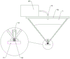
As shown in fig. 5, a container cover 10 is arranged above the ink container 1, and an air faucet 6 is arranged on the container cover 10, the ink container 1 can be designed to be conical, after the container cover 10 is closed, the inside of the ink container 1 is in a sealed state, and the air faucet 6 is connected with a compression air pump 61 to pressurize the sealed ink container 1; the ink outlet 11 can be provided with a pressure valve 12, the pressure valve 12 is a spring linkage structure, namely, under a certain pressure, the push rod is pushed downwards to make the valve ball separate from the ink outlet 11, so that automatic ink discharging is realized, and when the pressure is removed, the push rod is reset by the spring to make the valve ball seal the ink outlet 11 again.
Ink can be manually applied to the ink container 1 after the container lid 10 is opened.
Furthermore, bagged ink can be placed in the ink container 1, namely the ink outlet 11 can be provided with a water guide column 13, the water guide column 13 is the same as a water guide column of a barreled water dispenser, the positioning of the bagged ink and the opening of the water outlet of the bagged ink are mainly facilitated, the water guide column 13 is communicated with a pressure valve 12, air pressure directly acts on the bagged ink, and the ink pushes the pressure valve 12 open through the water guide column 13 to discharge the ink. The bagged ink is convenient to replace, the bagged ink is similar to barreled water and is directly spliced with the water guide column 13, and after the ink in the ink bag is used up, the ink can be filled only by opening the container cover 10, taking out an empty bag and replacing new bagged ink. Adopt flexible bagged ink, make whole ink container 1 relatively independent, it is simple, convenient for the processing of printing ink, can make equipment keep accelerating the operation of transform printing ink colour under clean state, can break equipment work at any moment, and can preserve the printing ink that has not distributed in the printing ink bag, it is fast and very convenient, and printing ink container 1 need not to wash after finishing using in addition, only need a small amount of cleaning solution pass through printing ink export 11 clean water guide post 13 and pressure valve 12 can.
It should be understood that the above-mentioned drawings are merely illustrative of the preferred embodiments of the present invention, and that the scope of the invention is not limited thereto.
Claims (4)
1. The utility model provides an automatic inking system of offset printing UV printing ink, mainly includes ink container (1), ink fountain groove (2) and even black pole (3), its characterized in that: the utility model discloses an ink container, including ink bucket groove (2), crossbeam (21) have in the ink bucket groove (2) top, crossbeam (21) is equipped with lateral shifting mechanism in the middle of the equipment, lateral shifting mechanism top is fixed with brace table (4), ink container (1) is fixed in on brace table (4), and still is equipped with rotary mechanism on brace table (4), the even pole (3) rotation of rotary mechanism drive, ink container (1) lower extreme is ink outlet (11), and ink outlet (11) press close to even pole (3), makes printing ink flow in ink bucket groove (2) along even pole (3).
2. The offset UV ink auto-inking system according to claim 1, wherein: the transverse moving mechanism is linked with the rotating mechanism.
3. An offset UV ink auto-inking system according to claim 1 or 2, characterized in that: and both sides of the ink hopper groove (2) are provided with limiting mechanisms (5).
4. An offset UV ink auto-inking system according to claim 1 or 2, characterized in that: a container cover (10) is arranged above the ink container (1), and an air nozzle (6) is arranged on the container cover (10).
Priority Applications (1)
| Application Number | Priority Date | Filing Date | Title |
|---|---|---|---|
| CN202010318363.5A CN111347757A (en) | 2020-04-21 | 2020-04-21 | Offset printing UV printing ink automatic inking system |
Applications Claiming Priority (1)
| Application Number | Priority Date | Filing Date | Title |
|---|---|---|---|
| CN202010318363.5A CN111347757A (en) | 2020-04-21 | 2020-04-21 | Offset printing UV printing ink automatic inking system |
Publications (1)
| Publication Number | Publication Date |
|---|---|
| CN111347757A true CN111347757A (en) | 2020-06-30 |
Family
ID=71195034
Family Applications (1)
| Application Number | Title | Priority Date | Filing Date |
|---|---|---|---|
| CN202010318363.5A Pending CN111347757A (en) | 2020-04-21 | 2020-04-21 | Offset printing UV printing ink automatic inking system |
Country Status (1)
| Country | Link |
|---|---|
| CN (1) | CN111347757A (en) |
Cited By (1)
| Publication number | Priority date | Publication date | Assignee | Title |
|---|---|---|---|---|
| CN113183624A (en) * | 2021-05-14 | 2021-07-30 | 苏州彩易达包装制品有限公司 | Printing ink adding process and portable ink adding mechanism |
Citations (6)
| Publication number | Priority date | Publication date | Assignee | Title |
|---|---|---|---|---|
| US3205816A (en) * | 1962-12-11 | 1965-09-14 | Winkler Fallert & Co Maschf | Ink fountain with ink recirculation means |
| CN202448474U (en) * | 2012-03-07 | 2012-09-26 | 陕西科技大学 | Automatic ink-stirring device for ink fountain of sheet-fed printing press |
| CN207591720U (en) * | 2017-12-01 | 2018-07-10 | 东莞市尚南电子科技有限公司 | A kind of optical glass CNC cuttings protection ink agitating device |
| CN207842312U (en) * | 2017-12-12 | 2018-09-11 | 深圳市科彩印务有限公司 | A kind of even black ink-feeding device of screen printer cycle |
| CN110450538A (en) * | 2019-09-10 | 2019-11-15 | 美盈森集团股份有限公司 | A kind of ink feeding system |
| CN212313012U (en) * | 2020-04-21 | 2021-01-08 | 汕头东风印刷股份有限公司 | Offset printing UV printing ink automatic inking system |
-
2020
- 2020-04-21 CN CN202010318363.5A patent/CN111347757A/en active Pending
Patent Citations (6)
| Publication number | Priority date | Publication date | Assignee | Title |
|---|---|---|---|---|
| US3205816A (en) * | 1962-12-11 | 1965-09-14 | Winkler Fallert & Co Maschf | Ink fountain with ink recirculation means |
| CN202448474U (en) * | 2012-03-07 | 2012-09-26 | 陕西科技大学 | Automatic ink-stirring device for ink fountain of sheet-fed printing press |
| CN207591720U (en) * | 2017-12-01 | 2018-07-10 | 东莞市尚南电子科技有限公司 | A kind of optical glass CNC cuttings protection ink agitating device |
| CN207842312U (en) * | 2017-12-12 | 2018-09-11 | 深圳市科彩印务有限公司 | A kind of even black ink-feeding device of screen printer cycle |
| CN110450538A (en) * | 2019-09-10 | 2019-11-15 | 美盈森集团股份有限公司 | A kind of ink feeding system |
| CN212313012U (en) * | 2020-04-21 | 2021-01-08 | 汕头东风印刷股份有限公司 | Offset printing UV printing ink automatic inking system |
Cited By (1)
| Publication number | Priority date | Publication date | Assignee | Title |
|---|---|---|---|---|
| CN113183624A (en) * | 2021-05-14 | 2021-07-30 | 苏州彩易达包装制品有限公司 | Printing ink adding process and portable ink adding mechanism |
Similar Documents
| Publication | Publication Date | Title |
|---|---|---|
| CN108479504B (en) | Printing ink dispersion treatment system for printing ink production | |
| CN214438148U (en) | Refining device for producing water-based environment-friendly high-performance low-temperature paint | |
| CN107998970B (en) | Electrolyte preparation equipment | |
| CN212313012U (en) | Offset printing UV printing ink automatic inking system | |
| CN109402897A (en) | A kind of textile fabric efficient process equipment | |
| CN111347757A (en) | Offset printing UV printing ink automatic inking system | |
| CN212313013U (en) | Offset printing ink inking container | |
| CN114833015B (en) | Gluing device for plate processing | |
| CN212604029U (en) | Offset printing ink inking structure | |
| CN212313061U (en) | Ink feeding groove cover for offset printing ink | |
| EP0404088A2 (en) | Device for feeding the inking unit of a printing press | |
| CN220576869U (en) | Ink scraping device for printing roller of printing machine | |
| CN218654867U (en) | Feeding device with adjustable size | |
| CN212701516U (en) | Vertical stirring mixing apparatus | |
| CN208469318U (en) | A kind of food package film printing equipment | |
| CN114405721B (en) | Insect prevention and insect expelling lime smearing device for forestry protection | |
| CN113634445B (en) | Environment-friendly glue spraying equipment capable of uniformly spraying glue | |
| CN218890421U (en) | Coating proportioning device | |
| CN221191546U (en) | Automatic feeding equipment easy to overhaul | |
| CN220802766U (en) | Movable batching cylinder for ink batching | |
| CN220056331U (en) | Automatic printing ink filling device for printing | |
| CN117685346B (en) | Automatic lubricating device for gear rack system | |
| CN214076352U (en) | High-efficient compounding device | |
| CN218872078U (en) | Coating processing mixing of colors unloader | |
| CN211994701U (en) | Automatic digital printing device |
Legal Events
| Date | Code | Title | Description |
|---|---|---|---|
| PB01 | Publication | ||
| PB01 | Publication | ||
| SE01 | Entry into force of request for substantive examination | ||
| SE01 | Entry into force of request for substantive examination |