CN1113220C - Coriolis mass flow/density sensor with single straight measuring tube - Google Patents
Coriolis mass flow/density sensor with single straight measuring tubeInfo
- Publication number
- CN1113220C CN1113220C CN97125385A CN97125385A CN1113220C CN 1113220 C CN1113220 C CN 1113220C CN 97125385 A CN97125385 A CN 97125385A CN 97125385 A CN97125385 A CN 97125385A CN 1113220 C CN1113220 C CN 1113220C
- Authority
- CN
- China
- Prior art keywords
- measuring tube
- plate
- fixed
- density sensor
- cantilever
- Prior art date
- Legal status (The legal status is an assumption and is not a legal conclusion. Google has not performed a legal analysis and makes no representation as to the accuracy of the status listed.)
- Expired - Lifetime
Links
Images


Classifications
-
- G—PHYSICS
- G01—MEASURING; TESTING
- G01F—MEASURING VOLUME, VOLUME FLOW, MASS FLOW OR LIQUID LEVEL; METERING BY VOLUME
- G01F1/00—Measuring the volume flow or mass flow of fluid or fluent solid material wherein the fluid passes through a meter in a continuous flow
- G01F1/76—Devices for measuring mass flow of a fluid or a fluent solid material
- G01F1/78—Direct mass flowmeters
- G01F1/80—Direct mass flowmeters operating by measuring pressure, force, momentum, or frequency of a fluid flow to which a rotational movement has been imparted
- G01F1/84—Coriolis or gyroscopic mass flowmeters
- G01F1/8409—Coriolis or gyroscopic mass flowmeters constructional details
- G01F1/8413—Coriolis or gyroscopic mass flowmeters constructional details means for influencing the flowmeter's motional or vibrational behaviour, e.g., conduit support or fixing means, or conduit attachments
- G01F1/8418—Coriolis or gyroscopic mass flowmeters constructional details means for influencing the flowmeter's motional or vibrational behaviour, e.g., conduit support or fixing means, or conduit attachments motion or vibration balancing means
-
- G—PHYSICS
- G01—MEASURING; TESTING
- G01F—MEASURING VOLUME, VOLUME FLOW, MASS FLOW OR LIQUID LEVEL; METERING BY VOLUME
- G01F1/00—Measuring the volume flow or mass flow of fluid or fluent solid material wherein the fluid passes through a meter in a continuous flow
- G01F1/76—Devices for measuring mass flow of a fluid or a fluent solid material
- G01F1/78—Direct mass flowmeters
- G01F1/80—Direct mass flowmeters operating by measuring pressure, force, momentum, or frequency of a fluid flow to which a rotational movement has been imparted
- G01F1/84—Coriolis or gyroscopic mass flowmeters
- G01F1/845—Coriolis or gyroscopic mass flowmeters arrangements of measuring means, e.g., of measuring conduits
- G01F1/8468—Coriolis or gyroscopic mass flowmeters arrangements of measuring means, e.g., of measuring conduits vibrating measuring conduits
- G01F1/849—Coriolis or gyroscopic mass flowmeters arrangements of measuring means, e.g., of measuring conduits vibrating measuring conduits having straight measuring conduits
-
- G—PHYSICS
- G01—MEASURING; TESTING
- G01N—INVESTIGATING OR ANALYSING MATERIALS BY DETERMINING THEIR CHEMICAL OR PHYSICAL PROPERTIES
- G01N11/00—Investigating flow properties of materials, e.g. viscosity, plasticity; Analysing materials by determining flow properties
- G01N11/10—Investigating flow properties of materials, e.g. viscosity, plasticity; Analysing materials by determining flow properties by moving a body within the material
- G01N11/16—Investigating flow properties of materials, e.g. viscosity, plasticity; Analysing materials by determining flow properties by moving a body within the material by measuring damping effect upon oscillatory body
- G01N11/162—Oscillations being torsional, e.g. produced by rotating bodies
-
- G—PHYSICS
- G01—MEASURING; TESTING
- G01N—INVESTIGATING OR ANALYSING MATERIALS BY DETERMINING THEIR CHEMICAL OR PHYSICAL PROPERTIES
- G01N9/00—Investigating density or specific gravity of materials; Analysing materials by determining density or specific gravity
- G01N9/002—Investigating density or specific gravity of materials; Analysing materials by determining density or specific gravity using variation of the resonant frequency of an element vibrating in contact with the material submitted to analysis
Abstract
This mass flow/density sensor (10), which can be installed in a pipe and through which a fluid to be measured flows during operation, is to be balanced over a wide density range, so that accurate measurements are possible. A single straight measuring tube (13) having a longitudinal axis (131) extends between its inlet end (11) and the outlet end (12) and is fixed to a support, e.g., a cylindrical tube (14, 14'). The support has a longitudinal centroidal line (141) which is parallel to, but does not coincide with, the longitudinal axis (131) of the measuring tube. A cantilever (15) is fixed to the measuring tube (13) midway between the inlet and outlet ends (11, 12) and in operation causes the measuring tube to vibrate either in a first fundamental flexural mode or in a second fundamental flexural mode having a higher frequency than this first mode. An excitation arrangement (16) disposed midway between the end pieces excites the measuring tube (13) in the second mode. Sensors (17, 18) for the motions of the measuring tube on the inlet and outlet side are positioned between the middle of the tube and the inlet and outlet ends, respectively. The support may be provided with a counterbalance. Because of the torsional vibrations exerted by the cantilever on the measuring tube, the sensor is also well suited for measuring the viscosity of the fluid. (B2) A Coriolis mass flow/density sensor is provided. The sensor includes a measuring tube for conducting a fluid. The measuring tube is fixed in a support and may be coupled to a pipe via an inlet tube and an outlet tube. The sensor further includes an excitation arrangement for vibrating the measuring tube in a predetermined vibration mode, a sensor arrangement for detecting vibrations of the measuring tube, and a brake assembly coupled to the measuring tube and the support.
Description
The present invention relates to a kind of Coriolis mass and flow/density sensor with measuring tube of single straight.
United States Patent (USP) 5531126 has been introduced a kind of Coriolis mass and flow/density sensor, it can be by means of being installed in the pipeline at the web member of entrance point with at the web member of endpiece, the fluid that the time will measure in work flows by it, and it comprises :-have longitudinal axis and at the measuring tube that extends and be fixed on the single straight on the web member between the web member;-be parallel to the pipe that measuring tube extends not the straight back cover that is flow through by fluid;-at the gusset plate of on the suction side with at the gusset plate of outlet side,---one of them entrance point with measuring tube partly is fixed on the thimble respective end portions, with---wherein another endpiece with measuring tube partly is fixed on the thimble respective end portions, so measuring tube and thimble are arranged side by side;-support column, its end are separately fixed on the web member and have the longitudinal axis of the symmetry that is parallel to the measuring tube longitudinal axis; And-some devices, they only act on the thimble and do flexural vibrations to evoke measuring tube, but the resonant frequency of its frequency and measuring tube is inconsistent, measuring tube and thimble vibrate in opposite phase in this case.
Coriolis mass and flow/the density sensor of this prior art, for given size design, balance on the mechanics is only in a narrow and small density value scope, be approximately nominal density ± 5%, that is to say that only in fact the power that is caused by the measuring tube vibration just can not pass to pipeline by web member when these density values.Above-mentioned scope by resonant frequency " outside " exciting enlarges, but compared with much bigger at the resonant frequency place needed hammer vibration energy of exciting.The mass flow/density sensor balance must be poor more, and this power and vibrational energy pass to pipeline will be big more; Therefore, make vibrational energy loss and increase measuring error.
This imbalance not only causes to produce under the situation about changing with a kind of fluid density in temperature to be disturbed, and especially brings interference when different time for example successively flows through the different fluid of pipeline measuring.
Because Coriolis-type mass flowmeter/densimeter should be suitable for the big as far as possible diverse fluid with different densities of measurement range, so a kind of Coriolis mass and flow/density sensor importantly is provided, they a big density range by above-mentioned meaning be balance and thereby can measure exactly.
For reaching this purpose, first kind of scheme of the present invention provides a kind of Coriolis mass and flow/density sensor, it can be installed in the pipeline and flow through the fluid that will measure when work, it comprises :-having the measuring tube of the single straight of longitudinal axis, measuring tube has an entrance point and an endpiece;-be fixed on the support on entrance point and the endpiece,---the longitudinal mass center line of support is parallel to the longitudinal axis of measuring tube but does not overlap with it;-cantilever,---this cantilever is fixed on the measuring tube of center between entrance point and the endpiece, and---it causes measuring tube or vibrates by first kind of basic crooked vibration shape, or vibrates by second kind of basic crooked vibration shape higher than the first basic crooked vibration shape frequency when work;-constantly cause the vibrator of measuring tube by the second basic crooked vibration shape vibration,---this vibrator is located between entrance point and the endpiece central authorities substantially; And-sensor of measuring tube on the suction side motion and the sensor of side buret outlet side motion, they lay respectively between measuring tube center and entrance point and the endpiece from they same distance places.
In first kind of most preferred embodiment of first kind of scheme of the present invention, support is a cylindrical tube, and it has the uniform wall of thickness and a longitudinal axis is arranged, and the latter is parallel to the longitudinal axis of measuring tube but does not overlap with it.
In second kind of most preferred embodiment of first kind of scheme of the present invention, support is a cylindrical tube, it has the just partly uniform wall of thickness and a longitudinal axis is arranged, the latter is parallel to the longitudinal axis of measuring tube, or overlap with it, tube wall is local at least in the first bus district relative with cantilever along diameter to be thicker than uniform wall thickness and/or to be adjacent in the first bus district of cantilever at least that the part is thinner than uniform wall thickness, in order that constitute a counterweight.
By the development of second kind of embodiment of first kind of scheme of the present invention, along the diameter counterweight relative with cantilever be fixed on the tube wall, local insert in the tube wall or with tube wall formation one.
The third most preferred embodiment of first kind of scheme of the present invention can be applied in the development of more top embodiment and second kind of embodiment, and wherein cantilever design is the form of perforated plate or dish, and plate or dish can be along the measuring tube slippages by means of this hole.Plate or coil preferably is made up of a semicircular ring part and a rectangle part above it, and partly the hole is coaxial therewith for semicircular ring.Advantageously plate or dish have a thickness partly that approximates the measuring tube diameter.
According to the development and the embodiment of first kind of scheme of the present invention, measuring tube has a circumferential rib and at outlet side a circumferential rib is arranged on the suction side, and they are arranged in the position of relevant sensor.
In the 4th kind of most preferred embodiment of first kind of scheme of the present invention, vibrator comprises-first, it with first exciting force along the directive effect of cantilever symmetry longitudinal axis and measuring tube longitudinal axis fulcrum on measuring tube, and-second portion, it acts on the cantilever end of measuring tube with direction second exciting force opposite with the first exciting force direction.
Second kind of scheme of the present invention provides a kind of Coriolis mass and flow/density sensor, and it can be contained in the pipeline and when work flows through the fluid that will measure, comprising :-have a measuring tube of the single straight of entrance point and endpiece;-be fixed on the entrance point place and round the import plate of measuring tube;-be fixed on the endpiece place and round the exit plate of measuring tube;-the first support plate, it is fixed on import plate and the exit plate and is parallel to first bus extension of measuring tube;-the second support plate, it is fixed on import plate and the exit plate and is parallel to along diameter measuring tube second bus relative with first bus extends;-cantilever,---this cantilever is fixed on the measuring tube of center between entrance point and the endpiece, and---it causes measuring tube or vibrates by first kind of basic crooked vibration shape, or vibrates by second kind of basic crooked vibration shape higher than the first basic crooked vibration shape frequency when work;-longitudinal rod is arranged in the position relative with cantilever and is fixed on first and second support plates, and this longitudinal rod plays counterweight;-vibrator,---it constantly causes measuring tube by the second basic crooked vibration shape vibration, and---this vibrator is located between entrance point and the endpiece central substantially; And-sensor of measuring tube on the suction side motion and the sensor of measuring tube outlet side motion, they lay respectively between measuring tube center and entrance point and the endpiece from they same distance places.
In first kind of most preferred embodiment of second kind of scheme of the present invention, cantilever is a plate, it has a front, a back, a twisting vibration axis and a hole that is parallel to the measuring tube axis, plate can slippage on measuring tube by means of this hole, this plate is by forming with coaxial circle section part and the system rectangle part thereon in hole, one of rectangle part end face that intersects at center and measuring tube diameter is fixed on the stationary plane of beam, the length of beam is greater than end face and first end and second end that exceeds this end face arranged, and they comprise the extendible portion of stationary plane respectively.
Development according to first kind of embodiment of second kind of scheme of the present invention, vibrator is made up of first excitation system on the stationary plane extendible portion that is fixed on beam first end and second excitation system on the stationary plane extendible portion that is fixed on beam second end, first and second excitation systems comprise first coil and second coil respectively, and they are passed through by reverse each other exciting electric current when work.
Second kind of development of second kind of scheme of the present invention also can be used for first kind of most preferred embodiment of second kind of scheme, by this second kind of development, in order to suppress and the different vibration shape of the second basic crooked vibration shape.-a possible penetration is arranged by in the zone of this plate at the front of plate twisting vibration axis, fix a first based on first clamping device of vortex principle;-a possible penetration is arranged by in the zone of this plate at the back of plate twisting vibration axis, fix a first based on second clamping device of vortex principle;-the first clamping device comprises a second portion, and it is installed on first bearing that is fixed at least on first support plate; And-second clamping device comprise a second portion, it is installed on second bearing that is fixed at least on first support plate.
In the most preferred embodiment of first kind of development of second kind of scheme of the present invention, the first of clamping device is a cylindrical permanent magnet, and the second portion of clamping device is a copper sheet.
These two kinds of schemes of the present invention, their embodiment and development can also further improve, as long as utilize isometric pipeline section to exceed entrance point respectively measuring tube and endpiece extends, isometric pipeline section free end separately is fixed in the shell.
By a kind of further development of the present invention, except that second kind of basic crooked vibration shape, also cause first kind of basic crooked vibration shape vibration.
An advantage of the invention is that the measuring accuracy of mass rate is (0kg/m in a big density range
3To 3000kg/m
3, 0kg/m wherein
3Corresponding to zero point of mass flow measurement during vacuum in the measuring tube) splendid.The mass flow/density sensor of short run trial production shows that for example, precision is in 0.1% scope of measured value.
Another significant advantage of the present invention is, it also is very suitable for measuring the viscosity of fluid, and this is the following fact known based on experts:
Only measuring tube or (also having) thus when the pipe of sensor is carried out twisting vibration apply shearing on fluid, could use the viscosity of Coriolis mass and flow/density sensor measurement fluid.Under the situation of the straight measuring tube that causes crooked vibration shape vibration, the vibration that at all do not twist, thereby do not have shearing.
Although under the situation of the especially U-shaped measuring tube of bending twisting vibration has taken place, their amplitude is too little, so in fact can not carry out viscosity measurement.The patent documentation of mentioning viscosity in conjunction with the Coriolis mass flow/density sensor is not a lot.
For example, 4938075 of United States Patent (USP)s are mentioned the Navier-Stokes equation, comprise shear viscosity in the equation, but do not measure.Some other patent document only relates to the viscosity compensation of the mass flow value that records; For example see United States Patent (USP) 5027662,4876879 and 4872351.
By single tube Coriolis mass and flow/density sensor of the present invention, not only the measurement for mass rate and density needs also to carry out on request flexural vibrations, and owing to exist cantilever to carry out twisting vibration round an axis in second kind of basic crooked vibration shape, the position of axis illustrates below.
In the present invention, the amplitude of this twisting vibration is enough to allow to measure the viscosity of fluid except that mass rate and density, only needs to increase a spot of electronic circuit.
For this viscosity measurement can be by means of the method for introducing in the document, these documents utilize especially pipe of mechanical vibrator, carry out the measurement of this viscosity in conjunction with the fluid density measurement.
For example, according to magazine " IEEE Transactions on Industrial Electronics andControl Instrumentation " in August, 1980,247 to 253 pages described, comprises the resonance quality factor of fluid at interior mechanical vibrator if measured, just can determine viscosity.This for example can accomplish by the electric current of measuring this device of exciting.
Embodiment by means of expression in the accompanying drawings describes the present invention in detail below.Design identical part in the accompanying drawings and adopt same symbol.In the accompanying drawing:
Fig. 1 is by the vertical view of biopsy cavity marker devices of first kind of embodiment of Coriolis mass and flow/density sensor of the present invention's first scheme;
Fig. 2 is along the cut-open view of Fig. 1 center line A-A;
Fig. 3 is along the cut-open view of Fig. 1 center line B-B;
Fig. 4 is along the cut-open view of Fig. 2 center line C-C;
Coriolis mass and flow/density sensor of Fig. 5 Fig. 1 to 4 is similar to the cut-open view of Fig. 3 after revising;
First kind of way of realization of second kind of embodiment of Fig. 6 first scheme is corresponding to the cut-open view of Fig. 1;
Second kind of way of realization of second kind of embodiment of Fig. 7 first scheme is corresponding to the cut-open view of Fig. 1;
The third way of realization of second kind of embodiment of Fig. 8 first scheme is corresponding to the cut-open view of Fig. 1;
The 4th kind of way of realization of second kind of embodiment of Fig. 9 first scheme is corresponding to the cut-open view of Fig. 1;
The 5th kind of way of realization of second kind of embodiment of Figure 10 first scheme is corresponding to the cut-open view of Fig. 1;
The 6th kind of way of realization of second kind of embodiment of Figure 11 first scheme is corresponding to the cut-open view of Fig. 1;
Figure 12 schematically illustrates the vibratory response of measuring tube and cantilever in can be applicable to first kind of basic crooked vibration shape of the present invention;
Figure 13 schematically illustrates the vibratory response of measuring tube and cantilever in being applied to second kind of basic crooked vibration shape of the present invention all the time;
A kind of development of Figure 14 the present invention first scheme is similar to the cut-open view of Fig. 2;
Figure 15 is by the Coriolis mass and flow/density sensor perspective plan view of alternative plan of the present invention;
The Coriolis mass and flow of Figure 16 Figure 15/density sensor perspective bottom view; And
The ratio magnification fluoroscopy vertical view of Figure 17 Figure 15 material particular.
The vertical view of the biopsy cavity marker devices of Fig. 1 has been represented the Coriolis mass and flow/density sensor 10 by the present invention's first scheme, and Fig. 2 represents along the cut-open view of the line A-A of Fig. 1.This mass flow/density sensor 10 is contained in one and wherein flows through in the given pipeline of the diameter that will measure fluid when using, and does not represent this pipeline for the purpose of view is clear.This sensor fluid is pipeline connection therewith hermetically.
Fig. 1 and 2 has represented required for this purpose flange 111 and 121, and they are connected on the end section 113 and 123 by short pipeline section 112 and 122, and the inlet end 11 of single measuring tube 13 and outlet end 12 stop respectively and are fixed in the end section; Measuring tube is straight and a longitudinal axis 131 is arranged.Mass flow/density sensor 10 also can be installed in the pipeline by the traditional stationary installation different with flange 111,121.
It in form for example is on the support of the framework of an opening or sealing or a cylindrical tube 14 that the entrance point 11 of measuring tube 13 and endpiece 12 are fixed on.The framework of sealing or cylindrical tube in the mode of a shell round measuring tube 13.Measuring tube 13 and end section 113,123 and end section 113,123 and support preferably weld together mutually.
Support has mass centre's longitudinal axis 141, and it is parallel to the longitudinal axis 131 of measuring tube 13 but does not overlap with it.This does not overlap can know from Fig. 3 and 4 and to find out, Fig. 3 and 4 represents respectively along the line B-B of Fig. 1 with along the cut-open view of the line C-C of Fig. 2.
Each of Fig. 1 to 4 has all been represented the cylindrical tube 14 of wall thickness uniformity.Therefore, pipe mass centre's longitudinal axis of 14 longitudinal axis of pipe therewith is consistent, so and measuring tube 13 and pipe 14 because above mentioned their collimation of axis is not concentric, that is to say not to be coaxial.
Represented that with Fig. 3 and 4 similar cut-open views 5 cantilever 15 also can be a disk 153, it can be by means of an eccentric orfice in slippage on the measuring tube 13 and be fixed on this pipe.Therefore disk 153 and measuring tube 13 are not concentric.
The plate or the dish that play cantilever action in Fig. 2 to 5 preferably have a thickness partly that approximates measuring tube 13 diameters greatly.
A visible vibrator 16 in Fig. 2 to 4, it is disposed in the cardinal principle central authorities between the end section 113,123.It for example is an electromagnetic type oscillator, and for example comprises that one is installed in support or manages coil block 161 and a permanent magnet 162 that is fixed on the cantilever 15 on 14.
Vibrator can be any in all kinds vibrator of being introduced for this purpose in the prior art that relates to Coriolis mass and flow/density sensor and coriolis mass flowmeters.
Vibrator can also be made up of first and second portion, the former with first exciting force along the directive effect of cantilever symmetry longitudinal axis and measuring tube longitudinal axis intersection point on measuring tube, the latter acts on the cantilever end of measuring tube (for simplicity among the figure less than representing) with direction second exciting force opposite with the first exciting force direction.
Fig. 2 has also schematically illustrated the sensor 17 (also can see) of measuring tube 13 on the suction sides motions in Fig. 3 and 4, and the sensor 18 of measuring tube 13 outlet sides motion.Sensor 17 and 18 is arranged between measuring tube center and entrance point section 113 and the endpiece section 123 apart from they equidistant places.Be preferably in sensing station place relevant on the measuring tube 13 and establish circumferential rib 132,133.
Can adopt various types of sensors of in the prior art that relates to Coriolis mass and flow/density sensor and coriolis mass flowmeters, being introduced for this purpose for sensor 17,18, such as displacement, speed or acceleration transducer, they for example press electrodynamic type or optical profile type work.
Fig. 6 to 11 with the corresponding cut-open view of Fig. 1 in represented to utilize pipe 14 ' the different ways of realization of the present invention's first scheme second kind of embodiment, pipe 14 ' inboard is still cylindrical, but it is different with first kind of embodiment in being illustrated in Fig. 1 to 5, it has only the wall thickness of local uniform, thus its longitudinal mass center line with the pipe 14 ' longitudinal axis inconsistent.
On the other hand, the pipe 14 ' this longitudinal axis overlap with the longitudinal axis of measuring tube 13.Therefore these two pipes are coaxial in Fig. 6 to 11, although manage 14 ' wall thickness be uneven.But this coincidence is not mandatory: these two longitudinal axis still can be parallel to each other.
In the way of realization of Fig. 6 to 11, the longitudinal axis of measuring tube 13 and support especially manage 14 ' the longitudinal mass center line enforceable parallel, draw according to pipe 14 ' uneven wall thickness.The result that this inhomogeneous wall thickness brings is, pipe 14 ' wall play cantilever 14 counterweights, that is to say the imbalance that compensation is caused by cantilever.
In first kind of way of realization of counterweight shown in Figure 6, pipe 14 ' wall along first bus relative with cantilever 15 diameters, along whole its thickness of length greater than the uniform wall thickness of this pipe remainder.This for example can reach by a longitudinal rib 142 along first bus is set, and especially fixes by melting welding or soldering.The width of longitudinal rib and height and material thereof must be considered the quality of cantilever 15 and pipe 14 ' wall thickness is selected uniformly.
In second kind of way of realization of the counterweight that is shown in Fig. 7, pipe 14 ' along the wall of press the first relative bus of diameter and cantilever 15 just passes through counterweight 143 and thickeies in the zone relative with cantilever 15.
Counterweight 143 still can by melting welding or soldering be fixed on pipe 14 ' on, maybe can insert and be fixed in the hole or hole that is formed in the tube wall, or constitute whole with pipe as shown in the figure.The width of counterweight 143, height and length and material thereof must be considered the quality of cantilever 15 and pipe 14 ' wall thickness is selected uniformly.
In the third way of realization of counterweight shown in Figure 8, pipe 14 ' wall along first bus relative, just at two section 144,145 uniform wall thickness that is thicker than pipe 14 ' remainder of whole length with cantilever 15 diameters.Section 144,145 extends from corresponding pipe 14 ' end towards pipe central authorities, has therefore formed a central sections 146, and it has manages 14 ' uniformly wall thickness.
In section 144,145 thicken still can be for example by pipe 14 ' on respectively melting welding or soldering longitudinal rib or such rib and control is integral reach.The width of segmentation 144,145, highly, length and material, must consider the quality of cantilever 15 and pipe 14 ' wall thickness is selected uniformly.
In the 4th kind of way of realization of counterweight shown in Figure 9, pipe 14 ' wall along being adjacent to second bus of cantilever 15, be made into along whole length of pipe thinner than the uniform wall thickness of the remainder of pipe.
In the 5th kind of form of implementation of counterweight shown in Figure 10, pipe 14 ' wall along being adjacent to second bus of cantilever 15, just in the central sections 147 relative with cantilever 15 by removing the material attenuate from wall; The pipe 14 ' remainder have uniform wall thickness.
In the 6th kind of form of implementation of counterweight shown in Figure 11, pipe 14 ' wall along being adjacent to second bus of cantilever 15, make thinner two section 148,149 of its whole length than the uniform wall thickness of pipe remainder.Section 148,149 from manage 14 ' respective end portions towards pipe 14 ' central authorities extend, therefore formed a central sections 150, it have pipe 14 ' uniform wall thickness.
Under the situation of the mass flow/density sensor shown in Fig. 9 to 11, the reducing of pipe 14 ' wall thickness reaches by remove material along second bus from tube wall, for example by planing or milling.The quality of the material that will remove respectively must consider the quality of cantilever 15 and pipe 14 ' wall thickness is determined uniformly.
Figure 12 and 13 foreword as an illustration, should recall 2 fixing and between 2 o'clock, excite the pipe of the no cantilever of flexural vibrations, it has a kind of unique crooked vibration shape.Pipe resembles a rope that is in vibration under its fundamental resonance frequency by this pattern vibration, and this fundamental resonance frequency is also referred to as keynote or first harmonic in theory of oscillation, and numerically this is minimum possible resonant frequency.In steady state (SS), rope and thereby pipe a unique antinode is arranged between two point of fixity, thereby do not have node; Node just is positioned at fixed point.
Different with this pipe that does not have cantilever, be provided with cantilever 15 by measuring tube 13 of the present invention, it is by the first and second crooked vibration shape vibrations, as will illustrating by means of Figure 12 and 13 now.These diagram expectation have been shown the central cross section of the vibrating mass of being made up of measuring tube 13 and cantilever 15, wherein, represent the rest position of vibrating mass in the central authorities of each figure, be in the peak excursion position at a left side and the right expression vibrating mass of figure, four-headed arrow is represented the direction vibrated.
Figure 12 represents the situation of the first basic crooked vibration shape vibration, wherein, when measuring tube is shifted to left cantilever 15 around the axis of measuring tube 13 to left movement; Cantilever 15 moves right when right-hand when measuring tube is shifted to.When cantilever omited to inner rotary, measuring tube was carried out the pure bending vibration.
This first basic crooked vibration shape has and corresponding " single order " resonant frequency of above mentioned resonant frequency, and numerically this is minimum possible frequency; For the given measuring tube of predetermined diameter, predetermined length and predetermined wall thickness and have predetermined quality and the cantilever of preliminary dimension for, this frequency for example is 400Hz.
Figure 13 represents the situation of the above mentioned second basic crooked vibration shape, and wherein, cantilever 15 moves right around the axis of measuring tube 13 when measuring tube is shifted to left; Cantilever 15 that is to say that to left movement cantilever rotates inwards when right-hand when measuring tube is shifted to.Therefore, the twisting vibration that in the flexural vibrations that measuring tube is implemented, superposeed as the first basic crooked vibration shape.
But the axis of this twisting vibration is obviously inconsistent parallel with it with the axis of measuring tube.The axis of twisting vibration is consistent with mass centre's line of whole mechanical qualities, and these quality participate in the vibration by the second basic crooked vibration shape.They are measuring tube quality, the cantilever quality that comprises fluid mass, the vibrator part quality that is fixed on the cantilever and vibrates thereupon, and, the clamping device first that will illustrate below also having if present.
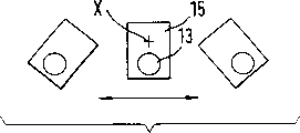
The twisting vibration axis is represented with X by one of the figure paper plane possible penetration in Figure 13; As shown in the figure, if the quality of vibrator is with respect to the vertical center line symmetry of cantilever, then it is positioned on this center line.This penetration X moves around in a small amount as the function of fluid density.
The second basic crooked vibration shape has " second order " resonant frequency, and it is than " single order " resonant frequency height of the first basic crooked vibration shape as defined above; For top mentioned given measuring tube, it is 900Hz.
According to the present invention, measuring tube 13 constantly is excited and does the second basic crooked vibration shape vibration, wherein, as shown in figure 13 and as top illustrated, cantilever 15 moves towards measuring tube when measuring tube outwards moves.
Because the resonant frequency of the second basic crooked vibration shape is the twice of the resonant frequency of the first basic crooked vibration shape, maybe can manufacture like this, so need be the excitation chain of phase-locked loop to the formal of vibrator 16 power supplies, for example can be referring to United States Patent (USP) 4801897, it can easily be designed to only excite the second basic crooked vibration shape.
Figure 14 represents a kind of development of the present invention's first scheme in the mode that is similar to Fig. 2, and it can be used for all illustrated so far embodiment and be used for Figure 15 and 16 represented embodiment.With used so far corresponding symbol identical numeral is arranged among Figure 14, but have asterisk.
The mass flow/density sensor 10 of Figure 14 ' in, the measuring tube 13 of vibration ' respectively by means of isometric straight length 13 " and 13
*Exceed entrance point and endpiece and be lengthened out straight length 13 " and 13
*With measuring tube 13 ' align.Pipeline section 13 ", 13
*Free end separately is fixed in the shell 19.Shell 19 for example comprise with flange 111, the 121 corresponding flanges 111 of Fig. 1 ', 121 '.
The perspective plan view of Figure 15 and the perspective plan view of Figure 16 have been represented by Coriolis mass and flow/density sensor 10 of the present invention " alternative plan.This sensor has the measuring tube 13 of single straight " and an entrance point 11 " and an endpiece 12 ".Fully round measuring tube 13 " import plate 213 and exit plate 223 be separately fixed on entrance point and the endpiece.
The member that plays the counterweight effect in alternative plan is a longitudinal rod 25, and it is arranged in cantilever 15 " the relative position place and be fixed on first and second support plates 24,34.In Figure 15 and 16, longitudinal rod 25 is arranged essentially parallel to measuring tube 13 " whole vibration length extend; But this is not mandatory; So be so in this embodiment just.
This system is made up of two support plates 24,34, import plate 213, exit plate 223 and longitudinal rod 25, and it has one and is parallel to measuring tube 13 " the longitudinal mass center line of axis.With regard to this character, Figure 15 and 16 structure and the structure of Fig. 1 to 5 are similar.
Measuring tube 13 " by vibrator 16 " excite and make the second basic crooked vibration shape vibration, vibrator 16 " act on cantilever 15 " on, and thereby also be arranged in cardinal principle central authorities between entrance point and the endpiece.The detail of vibrator will be below in conjunction with Figure 17 explanation.
Measuring tube 13 " in the motion of on the suction side and outlet side respectively by sensor 17 " and 18 " detection, they are arranged between the central authorities of measuring tube and entrance point and the endpiece and from them identical distance.
In Figure 15 and 16, represented that by drawn head of screw above-mentioned support plate 24,34 can be by means of screw retention on end plate 213,223 and be fixed on the longitudinal rod 25.But this is not mandatory; Other fixed form that is suitable for that also can adopt experts to know.
The alternative plan that is illustrated among Figure 15 and 16 is similar to the development of first scheme shown in Figure 14 at the design aspect of its mechanical vibrating system.Measuring tube 13 in this alternative plan " also respectively by means of straight isometric pipeline section 13
#With 13
+Exceed entrance point and endpiece is lengthened out, pipeline section 13
#With 13
+With measuring tube 13 " align.
Figure 15 and 16 represents that also casing cover 191 and 192 respectively has system coupling part 193 and 194 thereon, this Coriolis mass and flow/density sensor 10 " can by their fluid-tight be installed in the pipeline of once mentioning the front.
Figure 17 is with the cantilever 15 in the schedule of proportion diagrammatic sketch 15 that amplifies " with vibrator 16 " and the perspective plan view of other parts relevant with vibrator.In the most preferred embodiment of alternative plan of the present invention, cantilever 15 " be designed to a plate.It has a front 154 and a parallel back, can't see the back in Figure 15 and 17.Cantilever 15 " hole arranged, plate can be by means of this hole at measuring tube 13 " go up slippage and be fixed on this measuring tube 13 " on.
This plate is similar in the structure of Fig. 1 to 4 like that by the circle section part 151 coaxial with the hole " and rectangle part 152 formed integrally therewith " form.Rectangle part 152 " the tested buret 13 in end face 155 centers " diameter intersect; Have only the sub-fraction of this end face 155 in Figure 17, to see, that is in the hole of beam 163.
Further develop by of the present invention,, especially, be provided with clamping device first 27 and second portion 37 based on vortex principle in order to suppress the first basic crooked vibration shape and the harmonic wave thereof in order to suppress and the different vibration shape of the second basic crooked vibration shape.
First 27 is fixed in the zone of front 154 of plate, and the axis of above-mentioned mechanical torsional vibration system has a possible penetration by front 154 there.
In a similar fashion, the first 37 of second clamping device is fixed in the zone of back of plate, and the axis of above-mentioned torsional vibration system has the back of a possible penetration by this plate there.
In Figure 15, almost can't see and thereby not the second portion of first clamping device of numbering (it should be a numbering 28) be installed on first bearing 29 that is fixed on first and second support plates 24,34.This bearing only is illustrated among Figure 15; It is omitted in Figure 17, in order that do not shelter from cantilever 15 " etc. sight line.
The second portion 38 of second clamping device is installed on second bearing 39 that is fixed on first and second support plates 24,34, just as shown in the figure by means of " footing " of knuckle.These two the most handy soft magnetic material manufacturings of bearing.
Two firsts 27,37 of clamping device comprise columniform permanent magnet, wherein can only see permanent magnet 271 and relevant bearing 272 in Figure 17.Two second portions of this of clamping device are copper sheets.
The instantaneous position of the axis of the twisting vibration of once mentioning above stable by means of clamping device.Prevent to form other shake type thus, those harmonic waves of the first basic crooked vibration shape and the harmonic wave and/or the second basic crooked vibration shape especially, the second basic crooked vibration shape has a twisting vibration axis that is different from the first basic crooked vibration shape.
Form this vibration shape or this harmonic wave is equivalent to significantly moving back and forth of twisting vibration axis, for example referring to Figure 12.As long as this stabilization just can take place in the axis of twisting vibration in the zone of clamping device second portion 28,38.
In two kinds of schemes of the present invention, can further improve measuring accuracy, as long as except the second basic crooked vibration shape, also excite the vibration of the first basic crooked vibration shape, so, must omit the clamping device of Figure 15 and 17 certainly.
The exciting of the first basic crooked vibration shape can utilize another phase-locked loop to reach, and it is worked on first order resonance frequency.Both comprise the phase shift component that the Coriolis effect of the vibration of second order resonant frequency causes in this case in the signal that sensor provides and also comprised the phase shift component that the Coriolis effect of the vibration of first order resonance frequency causes.Because these two resonant frequencies approximately differ 2 times, so these two phase shift component can easily be separated by means of electronic installation.
Claims (20)
1, Coriolis mass and flow/density sensor, it can be contained in the pipeline and when work flows through the fluid that will measure, comprising:
-having the measuring tube of the single straight of longitudinal axis, measuring tube has an entrance point and an endpiece;
-be fixed on the support on entrance point and the endpiece,
---the longitudinal mass center line of support is parallel to the longitudinal axis of measuring tube but does not overlap with it;
-cantilever,
---this cantilever is fixed on the measuring tube of center between entrance point and the endpiece, and
---it causes measuring tube or vibrates by first kind of basic crooked vibration shape, or vibrates by second kind of basic crooked vibration shape higher than the first basic crooked vibration shape frequency when work;
-constantly cause the vibrator of measuring tube by the second basic crooked vibration shape vibration,
---this vibrator is located at central authorities between entrance point and the endpiece; And
The sensor of the sensor of-measuring tube on the suction side motion and the motion of measuring tube outlet side, they lay respectively between measuring tube center and entrance point and the endpiece from they same distance places.
According to the described Coriolis mass and flow/density sensor of claim 1, it is characterized in that 2, support is a cylindrical tube, it has the uniform wall of thickness and a longitudinal axis is arranged, and the latter is parallel to the longitudinal axis of measuring tube but does not overlap with it.
3, according to the described Coriolis mass and flow/density sensor of claim 1, it is characterized in that, support is a cylindrical tube, it has the just partly uniform wall of thickness and a longitudinal axis is arranged, the latter is parallel to the longitudinal axis of measuring tube, or overlap with it, tube wall in the first bus district relative with cantilever along diameter at least the part be thicker than uniform wall thickness and/or be adjacent in the first bus district of cantilever at least that the part is thinner than uniform wall thickness, in order that constitute a counterweight.
4, according to the described Coriolis mass and flow/density sensor of claim 3, it is characterized in that, along the diameter counterweight relative with cantilever be fixed on the tube wall, the local insertion in the tube wall or with tube wall constitute one.
5, according to the described Coriolis mass and flow/density sensor of claim 1, it is characterized in that, cantilever design be dish with holes or plate by means of this hole, dish or plate can be along the measuring tube slippages.
According to the described Coriolis mass and flow/density sensor of claim 5, it is characterized in that 6, plate or dish are made up of a semicircular ring part and a rectangle part above it, the former is coaxial with this hole.
According to the described Coriolis mass and flow/density sensor of claim 5, it is characterized in that 7, plate or dish have a thickness partly that is about the measuring tube diameter.
According to the described Coriolis mass and flow/density sensor of claim 1, it is characterized in that 8, measuring tube has a circumferential rib and at outlet side a circumferential rib arranged on the suction side, they are arranged in the position of relevant sensor.
9, according to the described Coriolis mass and flow/density sensor of claim 1, it is characterized in that vibrator comprises
-one first, it with first exciting force along the directive effect of cantilever symmetry longitudinal axis and measuring tube longitudinal axis intersection point on measuring tube, and
-one second portion, it acts on the cantilever end of measuring tube with direction second exciting force opposite with the first exciting force direction.
According to the described Coriolis mass and flow/density sensor of one of claim 1 to 9, it is characterized in that 10, measuring tube utilizes isometric pipeline section to exceed entrance point respectively and endpiece extends, the free end separately of isometric pipeline section is fixed in the shell.
11, according to the described Coriolis mass and flow/density sensor of claim 1, it is characterized in that, except that second kind of basic crooked vibration shape, also evoke first kind of basic crooked vibration shape vibration.
12, Coriolis mass and flow/density sensor, it can be contained in the pipeline and when work flows through the fluid that will measure, comprising:
-have a measuring tube of the single straight of entrance point and endpiece;
-be fixed on the entrance point place and round the import plate of measuring tube;
-be fixed on the endpiece place and round the exit plate of measuring tube;
-the first support plate, it is fixed on import plate and the exit plate and is parallel to first bus extension of measuring tube;
-the second support plate, it is fixed on import plate and the exit plate and is parallel to along diameter measuring tube second bus relative with first bus extends;
-cantilever,
---this cantilever is fixed on the measuring tube of center between entrance point and the endpiece, and
---it causes measuring tube or vibrates by first kind of basic crooked vibration shape, or vibrates by second kind of basic crooked vibration shape higher than the first basic crooked vibration shape frequency when work;
-longitudinal rod is arranged in the position relative with cantilever and is fixed on first and second support plates, and this longitudinal rod plays counterweight;
-vibrator,
---it constantly causes measuring tube by the second basic crooked vibration shape vibration, and
---this vibrator is located between entrance point and the endpiece central substantially; And
The sensor of the sensor of-measuring tube on the suction side motion and the motion of measuring tube outlet side, they lay respectively between measuring tube center and entrance point and the endpiece from they same distance places.
13, according to the described Coriolis mass and flow/density sensor of claim 12, it is characterized in that, cantilever is a plate, it has a front, a back, a twisting vibration axis and a hole that is parallel to the measuring tube axis, plate can slippage on measuring tube by means of this hole, this plate is by forming with coaxial circle section part and the system rectangle part thereon in hole, one of rectangle part end face that intersects at center and measuring tube diameter is fixed on the stationary plane of beam, the length of beam is greater than end face and first end and second end that exceeds this end face arranged, and they comprise the extendible portion of stationary plane respectively.
14, according to the described Coriolis mass and flow/density sensor of claim 13, it is characterized in that, vibrator is made up of first excitation system on the stationary plane extendible portion that is fixed on beam first end and second excitation system on the stationary plane extendible portion that is fixed on beam second end, first and second excitation systems comprise first coil and second coil respectively, and they are passed through by reverse each other exciting electric current when work.
15, according to the described Coriolis mass and flow/density sensor of claim 13, it is characterized in that, in order to suppress and the different vibration shape of the second basic crooked vibration shape,
-a possible penetration is arranged by in the zone of this plate at the front of plate twisting vibration axis, fix a first based on first clamping device of vortex principle;
-a possible penetration is arranged by in the zone of this plate at the back of plate twisting vibration axis, fix a first based on second clamping device of vortex principle;
-the first clamping device comprises a second portion, and it is installed on first bearing that is fixed at least on first support plate; And
-the second clamping device comprises a second portion, and it is installed on second bearing that is fixed at least on first support plate.
16, according to the described Coriolis mass and flow/density sensor of claim 14, it is characterized in that, in order to suppress and the different vibration shape of the second basic crooked vibration shape,
-a possible penetration is arranged by in the zone of this plate at the front of plate twisting vibration axis, fix a first based on first clamping device of vortex principle;
-a possible penetration is arranged by in the zone of this plate at the back of plate twisting vibration axis, fix a first based on second clamping device of vortex principle;
-the first clamping device comprises a second portion, and it is installed on first bearing that is fixed at least on first support plate; And
-the second clamping device comprises a second portion, and it is installed on second bearing that is fixed at least on first support plate.
According to the described Coriolis mass and flow/density sensor of claim 15, it is characterized in that 17, the first of clamping device is a cylindrical permanent magnet; And the second portion of clamping device is a copper sheet.
According to the described Coriolis mass and flow/density sensor of claim 16, it is characterized in that 18, the first of clamping device is a cylindrical permanent magnet; And the second portion of clamping device is a copper sheet.
According to the described Coriolis mass and flow/density sensor of one of claim 12 to 18, it is characterized in that 19, measuring tube utilizes isometric pipeline section to exceed entrance point respectively and endpiece extends, isometric pipeline section free end separately is fixed in the shell.
20, according to the described Coriolis mass and flow/density sensor of claim 10, it is characterized in that, except that second kind of basic crooked vibration shape, also evoke second kind of basic crooked vibration shape vibration.
Applications Claiming Priority (6)
| Application Number | Priority Date | Filing Date | Title |
|---|---|---|---|
| EP96119849 | 1996-12-11 | ||
| EP96119849.6 | 1996-12-11 | ||
| EP97100582 | 1997-01-16 | ||
| EP97100582.2 | 1997-01-16 | ||
| EP97810559.1 | 1997-08-08 | ||
| EP97810559A EP0849568B1 (en) | 1996-12-11 | 1997-08-08 | Coriolis massflow/density sensor with a single straight measuring tube |
Publications (2)
| Publication Number | Publication Date |
|---|---|
| CN1193733A CN1193733A (en) | 1998-09-23 |
| CN1113220C true CN1113220C (en) | 2003-07-02 |
Family
ID=51264535
Family Applications (1)
| Application Number | Title | Priority Date | Filing Date |
|---|---|---|---|
| CN97125385A Expired - Lifetime CN1113220C (en) | 1996-12-11 | 1997-12-10 | Coriolis mass flow/density sensor with single straight measuring tube |
Country Status (7)
| Country | Link |
|---|---|
| US (3) | US6006609A (en) |
| EP (1) | EP0849568B1 (en) |
| JP (1) | JP2872205B2 (en) |
| CN (1) | CN1113220C (en) |
| DE (1) | DE59700185D1 (en) |
| DK (1) | DK0849568T3 (en) |
| ES (1) | ES2135285T3 (en) |
Families Citing this family (129)
| Publication number | Priority date | Publication date | Assignee | Title |
|---|---|---|---|---|
| DE102013101369B4 (en) | 2013-02-12 | 2021-02-18 | Endress + Hauser Flowtec Ag | Coriolis mass flow meter |
| EP0849568B1 (en) | 1996-12-11 | 1999-06-02 | Endress + Hauser Flowtec AG | Coriolis massflow/density sensor with a single straight measuring tube |
| EP0905488A3 (en) * | 1997-09-30 | 1999-04-21 | Yokogawa Electric Corporation | Coriolis mass flowmeter |
| US6092429A (en) † | 1997-12-04 | 2000-07-25 | Micro Motion, Inc. | Driver for oscillating a vibrating conduit |
| US5979246A (en) * | 1998-02-09 | 1999-11-09 | Micro Motion, Inc. | Spring rate balancing of the flow tube and a balance bar in a straight tube Coriolis flowmeter |
| DE19840782C2 (en) * | 1998-09-08 | 2001-09-06 | Krohne Messtechnik Kg | Mass flow meter |
| DE59904728D1 (en) | 1998-12-11 | 2003-04-30 | Flowtec Ag | Coriolis mass flow / DENSITY METER |
| DE19908072C2 (en) * | 1999-02-12 | 2002-10-17 | Krohne Ag Basel | The mass flow meter |
| US6412355B1 (en) | 1999-05-20 | 2002-07-02 | Endress + Hauser Flowtec Ag | Coriolis-type flow meter and method for measuring the mass flow rate of a gaseous or vaporous fluid |
| US6408700B1 (en) | 1999-06-07 | 2002-06-25 | Endress + Hauser Flowtec Ag | Mass flow rate measurement circuit and method for a mass flow/density meter |
| US6354154B1 (en) * | 1999-06-30 | 2002-03-12 | Micro Motion, Inc. | Balance bar for a coriolis flowmeter |
| US6374478B1 (en) * | 1999-06-30 | 2002-04-23 | Micro Motion, Inc. | Method for manufacturing a Coriolis flow meter assembly |
| DE10002635C2 (en) * | 2000-01-21 | 2003-02-20 | Krohne Ag Basel | Method for determining at least one characteristic quantity of a mass flow meter |
| US6684716B2 (en) * | 2000-04-07 | 2004-02-03 | Kazumasa Ohnishi | Coriolis flowmeter |
| DE10017963C2 (en) * | 2000-04-12 | 2003-01-30 | Krohne Ag Basel | Mass Flow Meter |
| EP1158289B1 (en) * | 2000-04-27 | 2003-06-25 | Endress + Hauser Flowtec AG | Vibration type measuring device and method of measuring a viscosity of a fluid |
| US6651513B2 (en) | 2000-04-27 | 2003-11-25 | Endress + Hauser Flowtec Ag | Vibration meter and method of measuring a viscosity of a fluid |
| EP1154254A1 (en) * | 2000-05-12 | 2001-11-14 | Endress + Hauser Flowtec AG | Vibration type measuring device and method of measuring the viscosity of a fluid |
| DE10020606A1 (en) * | 2000-04-27 | 2001-10-31 | Flowtec Ag | Fluid viscosity measuring instrument oscillates measurement tube for generating viscous frictions in fluid |
| US6711958B2 (en) | 2000-05-12 | 2004-03-30 | Endress + Hauser Flowtec Ag | Coriolis mass flow rate/density/viscoy sensor with two bent measuring tubes |
| US6694279B2 (en) | 2001-02-16 | 2004-02-17 | Micro Motion, Inc. | Methods, apparatus, and computer program products for determining structural motion using mode selective filtering |
| US6466880B2 (en) | 2001-02-16 | 2002-10-15 | Micro Motion, Inc. | Mass flow measurement methods, apparatus, and computer program products using mode selective filtering |
| US6535826B2 (en) | 2001-02-16 | 2003-03-18 | Micro Motion, Inc. | Mass flowmeter methods, apparatus, and computer program products using correlation-measure-based status determination |
| US6691583B2 (en) * | 2001-04-24 | 2004-02-17 | Endress + Hauser Flowtec Ag | Vibratory transducer |
| RU2315974C2 (en) * | 2001-06-19 | 2008-01-27 | Эндресс+Хаузер Флоутек Аг | Viscosity meter |
| US6662120B2 (en) * | 2001-06-19 | 2003-12-09 | Endress + Hauser Flowtec Ag | Excitation circuits for coriolis mass flowmeters |
| DE10138323C1 (en) * | 2001-08-10 | 2003-04-17 | Danfoss As | Mass flow meter and method for measuring a mass flow |
| US6910366B2 (en) | 2001-08-24 | 2005-06-28 | Endress + Hauser Flowtec Ag | Viscometer |
| EP1291639B1 (en) * | 2001-08-24 | 2013-11-06 | Endress + Hauser Flowtec AG | Viscosity measuring device |
| DE10159809B4 (en) | 2001-12-05 | 2020-07-16 | Endress + Hauser Flowtec Ag | Vibration type sensor |
| DE10220734C1 (en) * | 2002-03-06 | 2003-04-24 | Krohne Ag Basel | Mass flow measurement device has connecting tubes satisfying equation relating compensation cylinder mass, Coriolis tube natural frequency, connecting tube modulus of elasticity |
| EP1502084B1 (en) | 2002-05-08 | 2020-01-15 | Endress + Hauser Flowtec AG | Torsional oscillation damper for a vibrating measuring transformer |
| DE10235322A1 (en) * | 2002-08-01 | 2004-02-12 | Endress + Hauser Flowtec Ag, Reinach | Vibration or Coriolis fluid mass flowmeter for measurement of mass flow, and or viscosity, has a single straight measurement pipe and an additional vibrator for generation of a torsional vibration and therefore fluid shear forces |
| US8100552B2 (en) * | 2002-07-12 | 2012-01-24 | Yechezkal Evan Spero | Multiple light-source illuminating system |
| EP1431719A1 (en) * | 2002-12-20 | 2004-06-23 | ABB Research Ltd. | Coriolis mass flow/density sensor with a single straight measuring conduit |
| EP1431720A1 (en) * | 2002-12-20 | 2004-06-23 | ABB Research Ltd. | Pendulum mass for mounting on a shaft or a conduit |
| US7013740B2 (en) * | 2003-05-05 | 2006-03-21 | Invensys Systems, Inc. | Two-phase steam measurement system |
| JP4565150B2 (en) * | 2003-05-12 | 2010-10-20 | 独立行政法人産業技術総合研究所 | Coriolis flow meter |
| US7059176B2 (en) * | 2003-06-18 | 2006-06-13 | Integrated Sensing Systems, Inc. | Resonant tube viscosity sensing device |
| US7072775B2 (en) * | 2003-06-26 | 2006-07-04 | Invensys Systems, Inc. | Viscosity-corrected flowmeter |
| DE10351312B4 (en) * | 2003-10-31 | 2009-05-07 | Abb Ag | Attachment and Coriolis mass flow meter with this attachment |
| DE10351311B3 (en) * | 2003-10-31 | 2005-06-30 | Abb Patent Gmbh | Coriolis mass flowmeter |
| DE102004007889A1 (en) * | 2004-02-17 | 2005-09-01 | Endress + Hauser Flowtec Ag, Reinach | Coriolis mass flow density meter for measuring a value representing mass flow of a medium flowing in a pipe line allows a two- or multi-phase medium to flow through a measuring tube |
| US7040180B2 (en) * | 2003-12-12 | 2006-05-09 | Endress + Hauser Flowtec Ag | Coriolis mass-flow measuring device |
| US7181982B2 (en) | 2003-12-12 | 2007-02-27 | Endress + Hauser Flowtec Ag | Coriolis mass flow measuring device |
| US7040181B2 (en) | 2004-03-19 | 2006-05-09 | Endress + Hauser Flowtec Ag | Coriolis mass measuring device |
| US7284449B2 (en) * | 2004-03-19 | 2007-10-23 | Endress + Hauser Flowtec Ag | In-line measuring device |
| DE102004018326B4 (en) | 2004-04-13 | 2023-02-23 | Endress + Hauser Flowtec Ag | Device and method for measuring a density and/or a viscosity of a fluid |
| DE102004023600A1 (en) * | 2004-05-13 | 2005-12-08 | Abb Research Ltd. | Flowing medium`s flow rate and density determining sensor has tube with inlet and outlet openings and connected with supporting component that is used as oscillator, where vibrations of tube are coupled at vibrations of oscillator |
| US7077014B2 (en) * | 2004-06-23 | 2006-07-18 | Endress + Hauser Flowtec Ag | Vibration-type measuring transducer |
| DK1914526T3 (en) | 2005-02-25 | 2017-10-23 | Endress & Hauser Flowtec Ag | VIBRATION TYPE MEASUREMENT SENSOR |
| CN1328578C (en) * | 2005-03-28 | 2007-07-25 | 哈尔滨工业大学 | Experimental device for measuring fluid density by means of vibration method |
| MX2007011594A (en) * | 2005-03-29 | 2007-12-10 | Micro Motion Inc | Coriolis flow meter and method for determining flow characteristics. |
| US7938021B2 (en) * | 2005-04-06 | 2011-05-10 | Micro Motion, Inc. | Compact vibratory flowmeter for measuring flow characteristics of a cement flow material |
| KR20100035185A (en) * | 2005-04-06 | 2010-04-02 | 마이크로 모우션, 인코포레이티드 | Compact vibratory flowmeter for measuring flow characteristics of a multi-phase flow material |
| US7555397B2 (en) * | 2005-05-31 | 2009-06-30 | Endress + Hauser Flowtec Ag | Coriolis mass flow meter and method for compensation of transmission errors of its input circuit |
| DE102005046319A1 (en) | 2005-09-27 | 2007-03-29 | Endress + Hauser Flowtec Ag | Two or multi-phase medium e.g. fluid`s, physical flow parameter e.g. flow rate, measuring method, involves producing measurement values representing parameter by considering pressure difference of medium and by usage of transfer function |
| US7490521B2 (en) * | 2005-11-15 | 2009-02-17 | Endress + Hauser Flowtec Ag | Measurement transducer of vibration type |
| US7472607B2 (en) * | 2005-11-15 | 2009-01-06 | Endress + Hauser Flowtec Ag | Measurement transducer of vibration type |
| US7475603B2 (en) * | 2005-11-15 | 2009-01-13 | Endress + Hauser Flowtec Ag | Measurement transducer of vibration-type |
| US7360452B2 (en) * | 2005-12-27 | 2008-04-22 | Endress + Hauser Flowtec Ag | In-line measuring devices and method for compensation measurement errors in in-line measuring devices |
| EP1987327A1 (en) | 2005-12-27 | 2008-11-05 | Endress+Hauser Flowtec AG | In-line measuring devices and method for compensating measurement errors in in-line measuring devices |
| US7360453B2 (en) * | 2005-12-27 | 2008-04-22 | Endress + Hauser Flowtec Ag | In-line measuring devices and method for compensation measurement errors in in-line measuring devices |
| US7555962B2 (en) * | 2006-03-22 | 2009-07-07 | Endress + Hauser Flowtec Ag | Measuring transducer of vibration-type |
| US7546777B2 (en) * | 2006-03-22 | 2009-06-16 | Endress + Hauser Flowtec Ag | Measuring transducer of vibration-type |
| US7631561B2 (en) * | 2006-03-22 | 2009-12-15 | Endress + Hauser Flowtec Ag | Measuring transducer of vibration-type |
| DE102006013601A1 (en) | 2006-03-22 | 2007-09-27 | Endress + Hauser Flowtec Ag | Transducer of the vibration type |
| CA2650549C (en) * | 2006-05-01 | 2013-04-02 | Micro Motion, Inc. | A balancing structure for a single curved tube coriolis flow meter |
| DE102006030962A1 (en) * | 2006-07-03 | 2008-01-31 | Endress + Hauser Flowtec Ag | Field device electronics powered by an external electrical power supply |
| DE102007058359A1 (en) * | 2006-12-07 | 2008-07-17 | Abb Ag | Method for attaching an attachment to the measuring tube of a Coriolis mass flowmeter and Coriolis mass flowmeter |
| DE102006062600B4 (en) | 2006-12-29 | 2023-12-21 | Endress + Hauser Flowtec Ag | Method for commissioning and/or monitoring an in-line measuring device |
| DE102007021099A1 (en) | 2007-05-03 | 2008-11-13 | Endress + Hauser (Deutschland) Ag + Co. Kg | Method for commissioning and / or reconfiguring a programmable field meter |
| DE102007030691A1 (en) | 2007-06-30 | 2009-01-02 | Endress + Hauser Flowtec Ag | Measuring system for a medium flowing in a process line |
| DE102007030700A1 (en) | 2007-06-30 | 2009-05-07 | Endress + Hauser Flowtec Ag | Measuring system for a medium flowing in a process line |
| DE102007030699A1 (en) | 2007-06-30 | 2009-01-15 | Endress + Hauser Flowtec Ag | Measuring system for a medium flowing in a process line |
| DE102007030690A1 (en) | 2007-06-30 | 2009-05-07 | Endress + Hauser Flowtec Ag | Measuring system for a medium flowing in a process line |
| DE102007063372A1 (en) | 2007-12-30 | 2009-07-02 | Endress + Hauser Flowtec Ag | Measuring system for a medium flowing in a process line |
| US20090025459A1 (en) * | 2007-07-23 | 2009-01-29 | Cardiac Pacemakers, Inc. | Implantable viscosity monitoring device and method therefor |
| DE102007037166A1 (en) | 2007-08-07 | 2009-02-19 | Endress + Hauser Flowtec Ag | gauge |
| DE102007058608A1 (en) | 2007-12-04 | 2009-06-10 | Endress + Hauser Flowtec Ag | Electric device |
| DE102008016235A1 (en) | 2008-03-27 | 2009-10-01 | Endress + Hauser Flowtec Ag | A method of operating a meter disposed on a rotary carousel filling machine |
| DE102008022373A1 (en) | 2008-05-06 | 2009-11-12 | Endress + Hauser Flowtec Ag | Measuring device and method for monitoring a measuring device |
| DE102008050113A1 (en) | 2008-10-06 | 2010-04-08 | Endress + Hauser Flowtec Ag | In-line measuring device |
| DE102008050115A1 (en) | 2008-10-06 | 2010-04-08 | Endress + Hauser Flowtec Ag | In-line measuring device |
| DE102008050116A1 (en) | 2008-10-06 | 2010-04-08 | Endress + Hauser Flowtec Ag | In-line measuring device |
| DE102009002289A1 (en) | 2009-04-08 | 2010-10-14 | Endress + Hauser Flowtec Ag | Method for determining period duration of periodic primary signal for determining e.g. mass flow rate, involves generating reference clock signal, and determining period duration based on number and reference values |
| US9341059B2 (en) * | 2009-04-15 | 2016-05-17 | Schlumberger Technology Corporation | Microfluidic oscillating tube densitometer for downhole applications |
| SG176125A1 (en) | 2009-06-10 | 2011-12-29 | Micro Motion Inc | Balance system for a vibrating flow meter |
| RU2534718C2 (en) | 2009-12-31 | 2014-12-10 | Эндресс + Хаузер Флоутек Аг | Measurement system for medium flowing in pipelines, and measurement method of pressure difference inside flowing medium |
| DK2519806T3 (en) | 2009-12-31 | 2018-05-22 | Flowtec Ag | Measurement system with a vibration type transducer |
| DE102010000761A1 (en) | 2010-01-11 | 2011-07-28 | Endress + Hauser Flowtec Ag | Measuring system i.e. measuring device and/or Coriolis or mass flow measuring device for medium e.g. gas and/or liquid, flowing in pipeline, has transmitter electronics generating measured value |
| DE102010000759A1 (en) | 2010-01-11 | 2011-07-14 | Endress + Hauser Flowtec Ag | Measuring system i.e. Coriolis mass flow measuring device, for measuring pressure difference of medium flowing in pipeline of industrial plant, has electronics housing generating measured value representing reynolds number for medium |
| DE102010000760B4 (en) | 2010-01-11 | 2021-12-23 | Endress + Hauser Flowtec Ag | A measuring system comprising a transducer of the vibration type for measuring a static pressure in a flowing medium |
| CN102686986B (en) | 2009-12-31 | 2015-01-28 | 恩德斯+豪斯流量技术股份有限公司 | Measuring system comprising a vibration-type transducer |
| EP2561603B1 (en) | 2010-04-19 | 2019-09-04 | Endress+Hauser Flowtec AG | Driver circuit for a measuring transducer and measuring system designed having same |
| DE202010006553U1 (en) | 2010-05-06 | 2011-10-05 | Endress + Hauser Flowtec Ag | Electronic measuring device with an optocoupler |
| DE102010030924A1 (en) | 2010-06-21 | 2011-12-22 | Endress + Hauser Flowtec Ag | Electronics housing for an electronic device or device formed therewith |
| DE102010039543A1 (en) | 2010-08-19 | 2012-02-23 | Endress + Hauser Flowtec Ag | Measuring system with a vibration-type transducer |
| DE102010035341B4 (en) | 2010-08-24 | 2013-07-04 | Krohne Ag | Method for determining the viscosity of a medium with a Coriolis mass flowmeter |
| DE102010044179A1 (en) | 2010-11-11 | 2012-05-16 | Endress + Hauser Flowtec Ag | Measuring system with a transducer of vibration type |
| DE102011006997A1 (en) * | 2011-04-07 | 2012-10-11 | Endress + Hauser Flowtec Ag | Frequency adjustment method for a pipe arrangement |
| DE102011006919A1 (en) * | 2011-04-07 | 2012-10-11 | Endress + Hauser Flowtec Ag | Method for trimming a pipe |
| DE102011076838A1 (en) | 2011-05-31 | 2012-12-06 | Endress + Hauser Flowtec Ag | Meter electronics for a meter device and meter device formed thereby |
| DE102011089808A1 (en) | 2011-12-23 | 2013-06-27 | Endress + Hauser Flowtec Ag | Method or measuring system for determining a density of a fluid |
| US20130333467A1 (en) * | 2012-06-19 | 2013-12-19 | Waters Technologies Corporation | Measuring Fluid Density |
| DE102013102708A1 (en) | 2013-03-18 | 2014-09-18 | Endress + Hauser Flowtec Ag | Vibration-type transducers and measuring system formed thereby |
| DE102013102711A1 (en) | 2013-03-18 | 2014-09-18 | Endress + Hauser Flowtec Ag | Vibration-type transducers and measuring system formed thereby |
| DE102013113689B4 (en) | 2013-12-09 | 2018-02-01 | Endress + Hauser Flowtec Ag | Density measuring device |
| CN105849510B (en) | 2013-12-20 | 2020-12-15 | 恩德斯+豪斯流量技术股份有限公司 | Coil |
| DE102013114731A1 (en) | 2013-12-20 | 2015-06-25 | Endress+Hauser Flowtec Ag | Kitchen sink |
| DE102013114742A1 (en) | 2013-12-20 | 2015-06-25 | Endress + Hauser Flowtec Ag | Method for fixing a metal tube to a metal body |
| CN103939087A (en) * | 2014-04-25 | 2014-07-23 | 中国石油集团渤海钻探工程有限公司 | Well logging density sensor |
| DE102014107849A1 (en) | 2014-06-04 | 2015-12-17 | Endress+Hauser Flowtec Ag | Measuring tube, Coriolis flowmeter and method of making a measuring tube for a flowmeter |
| DE102014119073A1 (en) * | 2014-12-18 | 2016-06-23 | Endress+Hauser Flowtec Ag | Vibration-type transducers |
| WO2016156903A1 (en) * | 2015-03-30 | 2016-10-06 | Micro Motion, Inc. | Improved vibrating member for a vibrating densitometer |
| CN107636443B (en) * | 2015-05-18 | 2021-04-20 | 高准公司 | Improved spool body for vibrating densitometer |
| DE102016114860A1 (en) | 2016-08-10 | 2018-02-15 | Endress + Hauser Flowtec Ag | Driver circuit and thus formed converter electronics or thus formed measuring system |
| DE102017121157A1 (en) | 2017-08-09 | 2019-02-14 | Endress+Hauser Flowtec Ag | Coil and transducer with such a coil |
| DE102017131199A1 (en) | 2017-12-22 | 2019-06-27 | Endress + Hauser Flowtec Ag | Coriolis mass flow meter |
| CN113242960A (en) | 2018-12-20 | 2021-08-10 | 恩德斯+豪斯流量技术股份有限公司 | Coriolis mass flowmeter |
| DE102018133117A1 (en) | 2018-12-20 | 2020-06-25 | Endress+Hauser Flowtec Ag | Coriolis mass flow meter |
| US20220099543A1 (en) | 2018-12-20 | 2022-03-31 | Endress+Hauser Flowtec Ag | Coriolis mass flow meter |
| WO2020126286A1 (en) | 2018-12-21 | 2020-06-25 | Endress+Hauser Flowtec Ag | Coriolis mass flowmeter with magnetic field detector |
| RU2714513C1 (en) * | 2019-07-26 | 2020-02-18 | Николай Васильевич Сизов | Coriolis flow meter - viscosimeter |
| DE102019133610A1 (en) | 2019-12-09 | 2021-06-10 | Endress + Hauser Flowtec Ag | Vibronic measuring system for measuring a mass flow of a fluid to be measured |
| DE102020127382A1 (en) | 2020-10-16 | 2022-04-21 | Endress+Hauser Flowtec Ag | Procedure for checking a vibronic measuring system |
| DE102021131866A1 (en) | 2021-12-03 | 2023-06-07 | Endress+Hauser Flowtec Ag | Method for detecting a foreign body in a medium |
| DE102022112523A1 (en) | 2022-05-18 | 2023-11-23 | Endress+Hauser Flowtec Ag | Vibronic measuring system |
| DE102022116111A1 (en) | 2022-06-28 | 2023-12-28 | Endress+Hauser Flowtec Ag | Vibronic measuring system |
Family Cites Families (19)
| Publication number | Priority date | Publication date | Assignee | Title |
|---|---|---|---|---|
| US4187721A (en) * | 1977-07-25 | 1980-02-12 | S & F Associates | Method and structure for flow measurement |
| US4524610A (en) * | 1983-09-02 | 1985-06-25 | National Metal And Refining Company, Ltd. | In-line vibratory viscometer-densitometer |
| DE3443234A1 (en) | 1984-11-27 | 1986-06-05 | Danfoss A/S, Nordborg | MASS FLOW MEASURING DEVICE ACCORDING TO THE CORIOLIS PRINCIPLE |
| DE8712331U1 (en) * | 1986-09-26 | 1988-01-28 | Flowtec Ag, Reinach, Basel, Ch | |
| US4777833A (en) * | 1986-11-12 | 1988-10-18 | Micro Motion, Inc. | Ferromagnetic drive and velocity sensors for a coriolis mass flow rate meter |
| US4938075A (en) * | 1987-02-12 | 1990-07-03 | Lew Hyok S | Convective inertia force flowmeter |
| US5027662A (en) * | 1987-07-15 | 1991-07-02 | Micro Motion, Inc. | Accuracy mass flow meter with asymmetry and viscous damping compensation |
| US4872351A (en) * | 1988-08-23 | 1989-10-10 | Micro Motion Incorporated | Net oil computer |
| US4876879A (en) * | 1988-08-23 | 1989-10-31 | Ruesch James R | Apparatus and methods for measuring the density of an unknown fluid using a Coriolis meter |
| EP0469448A1 (en) * | 1990-07-28 | 1992-02-05 | KROHNE MESSTECHNIK MASSAMETRON GmbH & Co. KG | Mass flow meter |
| DE4124295A1 (en) * | 1991-07-22 | 1993-01-28 | Krohne Ag | MASS FLOW MEASURING DEVICE |
| EP0547455B1 (en) * | 1991-12-19 | 1996-09-18 | Krohne AG | Mass flow rate meter |
| ES2068020T3 (en) * | 1992-11-06 | 1995-04-01 | Flowtec Ag | MASS FLOW METER ACCORDING TO THE PRINCIPLE OF CORIOLIS. |
| US5347874A (en) * | 1993-01-25 | 1994-09-20 | Micro Motion, Incorporated | In-flow coriolis effect mass flowmeter |
| DK0660920T3 (en) * | 1993-07-21 | 1999-12-13 | Flowtec Ag | Coriolis mass flow sensor |
| US5691485A (en) * | 1994-06-06 | 1997-11-25 | Oval Corporation | Coaxial double tube type Coriolis flowmeter |
| JPH08247816A (en) * | 1995-03-09 | 1996-09-27 | Fuji Electric Co Ltd | Mass flowmeter |
| US5796012A (en) * | 1996-09-19 | 1998-08-18 | Oval Corporation | Error correcting Coriolis flowmeter |
| EP0849568B1 (en) | 1996-12-11 | 1999-06-02 | Endress + Hauser Flowtec AG | Coriolis massflow/density sensor with a single straight measuring tube |
-
1997
- 1997-08-08 EP EP97810559A patent/EP0849568B1/en not_active Expired - Lifetime
- 1997-08-08 DK DK97810559T patent/DK0849568T3/en active
- 1997-08-08 DE DE59700185T patent/DE59700185D1/en not_active Expired - Lifetime
- 1997-08-08 ES ES97810559T patent/ES2135285T3/en not_active Expired - Lifetime
- 1997-09-30 US US08/940,644 patent/US6006609A/en not_active Expired - Lifetime
- 1997-12-10 CN CN97125385A patent/CN1113220C/en not_active Expired - Lifetime
- 1997-12-11 JP JP9341520A patent/JP2872205B2/en not_active Expired - Lifetime
-
1999
- 1999-10-07 US US09/414,268 patent/US6401548B1/en not_active Expired - Lifetime
-
2002
- 2002-04-30 US US10/135,625 patent/US6647807B2/en not_active Expired - Lifetime
Also Published As
| Publication number | Publication date |
|---|---|
| US6401548B1 (en) | 2002-06-11 |
| EP0849568A1 (en) | 1998-06-24 |
| EP0849568B1 (en) | 1999-06-02 |
| CN1193733A (en) | 1998-09-23 |
| DE59700185D1 (en) | 1999-07-08 |
| DK0849568T3 (en) | 1999-11-15 |
| ES2135285T3 (en) | 1999-10-16 |
| US20020117010A1 (en) | 2002-08-29 |
| JPH10185646A (en) | 1998-07-14 |
| US6647807B2 (en) | 2003-11-18 |
| US6006609A (en) | 1999-12-28 |
| JP2872205B2 (en) | 1999-03-17 |
Similar Documents
| Publication | Publication Date | Title |
|---|---|---|
| CN1113220C (en) | Coriolis mass flow/density sensor with single straight measuring tube | |
| CN1192216C (en) | Method and apparatus for a sensitivity enhancing blance bar | |
| RU2589506C2 (en) | Vibration-type measurement sensor and measuring system for measurement of density and/or percentage mass flow rate | |
| CN100335866C (en) | Transducer of the vibration type | |
| JP4108081B2 (en) | Vibration transducer | |
| CN1267711C (en) | Vibratory transducer | |
| RU2492430C2 (en) | Vibratory sensor, and flow monitoring and metering instrument with said sensor | |
| RU2460973C2 (en) | Vibration flow meter for determining one or more parameters of multiphase flowing fluid | |
| JP2731381B2 (en) | Coriolis mass flow sensor with only one measuring tube | |
| CN1934425A (en) | Coriolis mass flowmeter | |
| KR100688692B1 (en) | Coriolis flowmeter having lateral mode stabilizer, and method of operating the coriolis flowmeter to increase the frequency separation | |
| CN1214237C (en) | Device for determining and/or monitoring predetermined filling level in container | |
| CN101080614B (en) | Vibratory measuring transducer | |
| RU2234684C2 (en) | Balancing rod of coriolis flowmeter and method of its manufacture | |
| CN1547663A (en) | Viscometer | |
| CN1890537A (en) | Coriolis mass flowmeter | |
| KR20060134212A (en) | Method and apparatus for force balancing | |
| CN101346612B (en) | Vibratory measuring transducer | |
| US10718649B2 (en) | Multi-channel flow tube | |
| JP2011085558A (en) | Dynamic balancing machine and vibrator support apparatus | |
| CN1173156C (en) | Method and for coriolis flowmeter having accuracy enhancing balance bar | |
| US6336370B1 (en) | Coriolis mass flow meter with thick wall measuring tube | |
| RU2295120C2 (en) | Vibration type measuring transformer | |
| US11226222B2 (en) | Vibratory measuring device having a measuring tube | |
| JP2984134B2 (en) | Coriolis flow meter |
Legal Events
| Date | Code | Title | Description |
|---|---|---|---|
| C10 | Entry into substantive examination | ||
| SE01 | Entry into force of request for substantive examination | ||
| C06 | Publication | ||
| PB01 | Publication | ||
| C14 | Grant of patent or utility model | ||
| GR01 | Patent grant | ||
| CX01 | Expiry of patent term | ||
| CX01 | Expiry of patent term |
Granted publication date: 20030702 |