CN111302093A - Intelligent pressurized powder conveying device - Google Patents
Intelligent pressurized powder conveying device Download PDFInfo
- Publication number
- CN111302093A CN111302093A CN202010254051.2A CN202010254051A CN111302093A CN 111302093 A CN111302093 A CN 111302093A CN 202010254051 A CN202010254051 A CN 202010254051A CN 111302093 A CN111302093 A CN 111302093A
- Authority
- CN
- China
- Prior art keywords
- threaded rod
- defeated
- fixedly connected
- defeated material
- pressurizing
- Prior art date
- Legal status (The legal status is an assumption and is not a legal conclusion. Google has not performed a legal analysis and makes no representation as to the accuracy of the status listed.)
- Withdrawn
Links
Images

Classifications
-
- B—PERFORMING OPERATIONS; TRANSPORTING
- B65—CONVEYING; PACKING; STORING; HANDLING THIN OR FILAMENTARY MATERIAL
- B65G—TRANSPORT OR STORAGE DEVICES, e.g. CONVEYORS FOR LOADING OR TIPPING, SHOP CONVEYOR SYSTEMS OR PNEUMATIC TUBE CONVEYORS
- B65G65/00—Loading or unloading
- B65G65/30—Methods or devices for filling or emptying bunkers, hoppers, tanks, or like containers, of interest apart from their use in particular chemical or physical processes or their application in particular machines, e.g. not covered by a single other subclass
- B65G65/34—Emptying devices
- B65G65/40—Devices for emptying otherwise than from the top
- B65G65/46—Devices for emptying otherwise than from the top using screw conveyors
-
- B—PERFORMING OPERATIONS; TRANSPORTING
- B65—CONVEYING; PACKING; STORING; HANDLING THIN OR FILAMENTARY MATERIAL
- B65D—CONTAINERS FOR STORAGE OR TRANSPORT OF ARTICLES OR MATERIALS, e.g. BAGS, BARRELS, BOTTLES, BOXES, CANS, CARTONS, CRATES, DRUMS, JARS, TANKS, HOPPERS, FORWARDING CONTAINERS; ACCESSORIES, CLOSURES, OR FITTINGS THEREFOR; PACKAGING ELEMENTS; PACKAGES
- B65D88/00—Large containers
- B65D88/54—Large containers characterised by means facilitating filling or emptying
- B65D88/64—Large containers characterised by means facilitating filling or emptying preventing bridge formation
- B65D88/68—Large containers characterised by means facilitating filling or emptying preventing bridge formation using rotating devices
-
- B—PERFORMING OPERATIONS; TRANSPORTING
- B65—CONVEYING; PACKING; STORING; HANDLING THIN OR FILAMENTARY MATERIAL
- B65G—TRANSPORT OR STORAGE DEVICES, e.g. CONVEYORS FOR LOADING OR TIPPING, SHOP CONVEYOR SYSTEMS OR PNEUMATIC TUBE CONVEYORS
- B65G2201/00—Indexing codes relating to handling devices, e.g. conveyors, characterised by the type of product or load being conveyed or handled
- B65G2201/04—Bulk
Abstract
The invention relates to the technical field of powder conveying equipment, and discloses an intelligent pressurized powder conveying device which comprises a material conveying tank, a pressurizing mechanism and a material conveying mechanism, wherein the pressurizing mechanism is arranged in the material conveying tank and comprises a U-shaped supporting plate, a pressurizing motor, a pressurizing plate and a first threaded rod, two ends of the lower side of the U-shaped supporting plate are respectively and fixedly connected with two sides of the upper end of the material conveying tank, the pressurizing motor is fixedly arranged at the center of the upper end of the U-shaped supporting plate, the lower end of the pressurizing motor is rotatably connected with the upper end of the first threaded rod through a first coupler, the lower end of the first threaded rod penetrates through the U-shaped supporting plate and extends to the lower part in the material conveying tank, and the upper end of the rod wall of the first threaded rod is rotatably connected with the U-shaped supporting plate. This pressurized powder conveyor of intelligence can stabilize the unloading and carry out the powder in succession evenly and carry, and avoids the unloading to block up, can also material loading in advance, improves work efficiency.
Description
Technical Field
The invention relates to the technical field of powder conveying equipment, in particular to an intelligent pressurized powder conveying device.
Background
The conveying device comprises a liquid pipeline conveying device and a solid belt conveying device, when the solid volume is small and is in a powder shape, the powder is easy to scatter by using the belt conveying device, and the conveying device is generally used for conveying by using a spiral conveying device.
However, in the prior art, when the powder conveying device conveys powder, feeding instability is easily generated, so that powder conveying is discontinuous, powder conveying capacity fluctuation is large, the powder can be added only after the powder in the device is conveyed, time is consumed, and working efficiency is affected, so that the intelligent pressurized powder conveying device is provided.
Disclosure of Invention
Technical problem to be solved
Aiming at the defects of the prior art, the invention provides the intelligent pressurized powder conveying device which has the advantages of stable blanking, continuous and uniform conveying, high working efficiency and the like, and solves the problems in the background art.
(II) technical scheme
In order to realize the purposes of stable blanking, continuous and uniform conveying and high working efficiency, the invention provides the following technical scheme: an intelligent pressurized powder conveying device comprises a material conveying tank, a pressurizing mechanism and a material conveying mechanism, wherein the pressurizing mechanism is arranged in the material conveying tank and comprises a U-shaped supporting plate, a pressurizing motor, a pressurizing plate and a first threaded rod, two ends of the lower side of the U-shaped supporting plate are fixedly connected with two sides of the upper end of the material conveying tank respectively, the pressurizing motor is fixedly arranged at the center of the upper end of the U-shaped supporting plate, the lower end of the pressurizing motor is rotatably connected with the upper end of the first threaded rod through a first coupler, the lower end of the first threaded rod penetrates through the U-shaped supporting plate and extends to the inner lower part of the material conveying tank, the upper end of the rod wall of the first threaded rod is rotatably connected with the U-shaped supporting plate through a first rolling bearing, the pressurizing plate is arranged in the inner horizontal position of the material conveying tank, a threaded hole is formed in the center of the upper end of the pressurizing plate and, the utility model discloses a material conveying mechanism, including the lateral wall fixedly connected with of increased pressure board, the lateral wall fixedly connected with of increased pressure board slider that two symmetries set up, two and slider assorted spouts are seted up to the inside wall of material conveying jar, the lower extreme fixedly connected with discharging pipe of material conveying jar, defeated material mechanism is located the below setting of material conveying jar, and the input of defeated material mechanism and the lower extreme fixed connection of discharging pipe, the left side upper end fixedly connected with feeder hopper of material conveying jar, the lower extreme of feeder hopper passes through the inlet pipe and sets up with the lateral wall intercommunication of material conveying jar, the inside of.
Preferably, the lower end of the first threaded rod is fixedly connected with a first rotating rod, the lower end of the first rotating rod extends to the lower portion of the interior of the discharge pipe and is arranged, and the rod wall of the first rotating rod is fixedly connected with a first spiral conveying blade.
Preferably, defeated material mechanism includes defeated feed cylinder, defeated material motor, second bull stick, second spiral delivery leaf, the lower extreme fixed connection of lateral wall upper end and the discharging pipe of defeated feed cylinder, the left end fixed connection of defeated material motor and defeated feed cylinder, the output of defeated material motor is rotated through the left end of second shaft joint and second bull stick and is connected, the right-hand member of second bull stick extends to the inside setting of defeated feed cylinder, and the pole wall of second bull stick passes through second antifriction bearing and is connected with the rotation of defeated feed cylinder, the pole wall of second bull stick is located the inside one end and the second spiral delivery leaf fixed connection of defeated feed cylinder.
Preferably, the inside of defeated material jar is equipped with the slide bar of two vertical settings, the upper end and the U-shaped backup pad fixed connection of slide bar, the lower extreme of slide bar and defeated material jar lower lateral wall fixed connection, the upper end of increased pressure board is seted up two and slide bar assorted through-hole and is passed through-hole and slide bar sliding connection.
Preferably, a discharge chute is formed in one side, far away from the feeding pipe, of the upper end of the inner side wall of the material conveying tank, and the upper end of the pressurizing plate is obliquely and downwards arranged towards the periphery.
Preferably, shutoff mechanism includes closing plate, fixed block, an internal thread section of thick bamboo and second threaded rod, the fixed block is located fixed connection with the upper end center of closing plate, the left end and the fixed block fixed connection of an internal thread section of thick bamboo, the right-hand member of second threaded rod extend to the inside of an internal thread section of thick bamboo and with internal thread section of thick bamboo threaded connection, the left end of second threaded rod runs through the left side wall of feeder hopper and extends to the outside setting of feeder hopper, and the pole wall of second threaded rod passes through third antifriction bearing and is connected with the feeder hopper rotation.
Preferably, the second threaded rod is located the outside one end fixed connection L shape handle of feeder hopper, the lower extreme left side fixedly connected with stopper of closing plate, the lower inside wall left end of feeder hopper seted up with stopper assorted spacing groove.
Preferably, the below of defeated material jar is equipped with the base, a plurality of evenly distributed's of the upper end fixedly connected with bracing piece of base, it is a plurality of the upper end of bracing piece all with the bottom fixed connection of defeated material jar.
(III) advantageous effects
Compared with the prior art, the invention provides an intelligent pressurized powder conveying device, which has the following beneficial effects:
1. the intelligent pressurized powder conveying device can contain powder through the arranged conveying tank, the powder enters the conveying cylinder through the discharging pipe, the second rotating rod can be driven to rotate through the arranged conveying motor, the second rotating rod can drive the second spiral conveying blade to rotate, the second spiral conveying blade can push the powder inside the conveying cylinder through rotation, so that the powder can be conveyed, the first threaded rod can be driven to rotate through the arranged pressurizing motor, the first threaded rod can drive the pressurizing plate to move downwards, the pressurizing plate can apply pressure downwards on the powder inside the conveying cylinder, so that the powder inside the conveying cylinder can continuously and uniformly enter the conveying cylinder, the conveying cylinder can continuously and uniformly convey the powder, the first threaded rod can also drive the first rotating rod to rotate, the first rotating rod can drive the first spiral conveying blade to rotate, so that the powder below the inner part of the conveying cylinder can be conveyed into the conveying cylinder, avoiding powder blockage.
2. This pressurized powder conveyor of intelligence, can carry out the shutoff with the upper end of inlet pipe through the closing plate that is equipped with, thereby when defeated material jar is defeated the material, can add the powder of treating the transport in to the feeder hopper, after the powder in defeated material jar is carried and is accomplished, remove the top to defeated material jar with the increased pressure board, it is rotatory that L shape handle can drive the second threaded rod to rotate, the second threaded rod is rotatory to drive the internal thread section of thick bamboo and move left, the internal thread section of thick bamboo can drive the fixed block and move left, the internal thread section of thick bamboo can drive the closing plate and move left, thereby can open the upper end of inlet pipe, thereby can make the powder in the feeder hopper get into defeated material jar, be convenient for improve.
Drawings
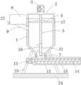
FIG. 1 is a schematic structural diagram of an intelligent pressurized powder conveying device according to the present invention;
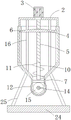
FIG. 2 is a schematic side view of an intelligent pressurized powder conveying apparatus according to the present invention;
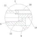
FIG. 3 is a schematic view of the internal structure of the hopper of FIG. 1;
fig. 4 is an enlarged view of a portion a of fig. 3.
In the figure: 1 material conveying tank, 2U-shaped supporting plates, 3 pressurizing motors, 4 pressurizing plates, 5 first threaded rods, 6 sliding blocks, 7 discharging pipes, 8 feeding hoppers, 9 feeding pipes, 10 first rotating rods, 11 first spiral conveying blades, 12 material conveying cylinders, 13 material conveying motors, 14 second rotating rods, 15 second spiral conveying blades, 16 sliding rods, 17 discharging chutes, 18 sealing plates, 19 fixing blocks, 20 internal thread cylinders, 21 second threaded rods, 22L-shaped handles, 23 limiting blocks, 24 bases and 25 supporting rods.
Detailed Description
The technical solutions in the embodiments of the present invention will be clearly and completely described below with reference to the drawings in the embodiments of the present invention, and it is obvious that the described embodiments are only a part of the embodiments of the present invention, and not all of the embodiments. All other embodiments, which can be derived by a person skilled in the art from the embodiments given herein without making any creative effort, shall fall within the protection scope of the present invention.
Referring to fig. 1-4, an intelligent pressurized powder conveying device comprises a material conveying tank 1, a pressurizing mechanism and a material conveying mechanism, wherein the pressurizing mechanism is arranged in the material conveying tank 1 and comprises a U-shaped support plate 2, a pressurizing motor 3, a pressurizing plate 4 and a first threaded rod 5, two ends of the lower side of the U-shaped support plate 2 are respectively and fixedly connected with two sides of the upper end of the material conveying tank 1, the pressurizing motor 3 is fixedly arranged at the center of the upper end of the U-shaped support plate 2, the lower end of the pressurizing motor 3 is rotatably connected with the upper end of the first threaded rod 5 through a first coupler, the lower end of the first threaded rod 5 penetrates through the U-shaped support plate 2 and extends to the lower part of the interior of the material conveying tank 1, the upper end of the rod wall of the first threaded rod 5 is rotatably connected with the U-shaped support plate 2 through a first rolling bearing, the pressurizing plate 4 is horizontally arranged in the interior of the material conveying tank 1, a threaded hole is formed in the center of the upper, slider 6 that two symmetries of lateral wall fixedly connected with of increased pressure plate 4 set up, two and slider 6 assorted spouts have been seted up to defeated material jar 1's inside wall, defeated material jar 1's lower extreme fixedly connected with discharging pipe 7, defeated material mechanism is located defeated material jar 1 below setting, and the input of defeated material mechanism and the lower extreme fixed connection of discharging pipe 7, defeated material jar 1's left side upper end fixedly connected with feeder hopper 8, feeder hopper 8's lower extreme passes through inlet pipe 9 and the lateral wall intercommunication setting of defeated material jar 1, feeder hopper 8's inside is equipped with shutoff mechanism.
The lower extreme fixedly connected with first bull stick 10 of first threaded rod 5, the lower extreme of first bull stick 10 extends to the inside below setting of discharging pipe 7, the first spiral delivery leaf 11 of pole wall fixedly connected with of first bull stick 10, first threaded rod 5 is rotatory to drive first bull stick 10 rotatory, first bull stick 10 is rotatory to drive first spiral delivery leaf 11 rotatory, thereby can carry the powder of 1 inside below of defeated material jar to defeated material mechanism in, avoid the powder to block up.
The material conveying mechanism comprises a material conveying cylinder 12, a material conveying motor 13, a second rotating rod 14 and a second spiral conveying blade 15, the upper end of the outer side wall of the material conveying cylinder 12 is fixedly connected with the lower end of a material discharging pipe 7, the material conveying motor 13 is fixedly connected with the left end of the material conveying cylinder 12, the output end of the material conveying motor 13 is rotatably connected with the left end of the second rotating rod 14 through a second shaft coupler, the right end of the second rotating rod 14 extends to the inner portion of the material conveying cylinder 12, the rod wall of the second rotating rod 14 is rotatably connected with the material conveying cylinder 12 through a second rolling bearing, one end, located inside the material conveying cylinder 12, of the rod wall of the second rotating rod 14 is fixedly connected with the second spiral conveying blade 15, and powder in the material conveying cylinder 12 can be conveyed.
The inside of defeated material jar 1 is equipped with the slide bar 16 of two vertical settings, slide bar 16's upper end and U-shaped backup pad 2 fixed connection, slide bar 16's lower extreme and defeated material jar 1 lower lateral wall fixed connection, the upper end of increased pressure board 4 seted up two with slide bar 16 assorted through-hole and through-hole and slide bar 16 sliding connection, can make increased pressure board 4 more stable when reciprocating.
One side that the inlet pipe 9 was kept away from to the inside wall upper end of defeated material jar 1 has seted up the blowpit 17, and the upper end of increased pressure board 4 sets up downwards to border slope all around, can arrange the powder of increased pressure board 4 top in defeated material jar 1.
The plugging mechanism comprises a sealing plate 18, a fixing block 19, an internal thread cylinder 20 and a second threaded rod 21, the fixing block 19 is fixedly connected with the center of the upper end of the sealing plate 18, the left end of the internal thread cylinder 20 is fixedly connected with the fixing block 19, the right end of the second threaded rod 21 extends to the inside of the internal thread cylinder 20 and is in threaded connection with the internal thread cylinder 20, the left end of the second threaded rod 21 penetrates through the left side wall of the feeding hopper 8 and extends to the outside of the feeding hopper 8, the rod wall of the second threaded rod 21 is rotatably connected with the feeding hopper 8 through a third rolling bearing, the second threaded rod 21 rotates to drive the internal thread cylinder 20 to move leftwards, the internal thread cylinder 20 can drive the fixing block 19 to move leftwards, the internal thread cylinder 20 can drive the sealing plate 18 to move leftwards, the upper end of the feeding pipe 9 can be opened.
Second threaded rod 21 is located the outside one end fixed connection L of feeder hopper 8 shape handle 22, and it is rotatory that people of being convenient for rotate L shape handle 22 and drive second threaded rod 21, and the lower extreme left side fixedly connected with stopper 23 of closing plate 18, the lower inside wall left end of feeder hopper 8 seted up with stopper 23 assorted spacing groove, it is more stable when can making closing plate 18 remove, and can make closing plate 18 correspond with inlet pipe 9 upper end position when moving rightly.
The below of defeated material jar 1 is equipped with base 24, a plurality of evenly distributed's of the upper end fixedly connected with bracing piece 25 of base 24, the upper end of a plurality of bracing pieces 25 all with defeated material jar 1's bottom fixed connection, can carry out the stable stay to conveyor.
To sum up, in use, the intelligent pressurized powder conveying device can contain powder through the provided material conveying tank 1, the powder enters the inside of the material conveying cylinder 12 through the discharging pipe 7, the material conveying motor 13 can drive the second rotating rod 14 to rotate, the second rotating rod 14 can drive the second spiral conveying blade 15 to rotate, the second spiral conveying blade 15 can push the powder inside the material conveying cylinder 12 to convey the powder, the first threaded rod 5 can be driven to rotate through the provided pressurizing motor 3, the first threaded rod 5 can drive the pressurizing plate 4 to move downwards, the pressurizing plate 4 can apply pressure downwards on the powder inside the material conveying tank 1, so that the powder inside the material conveying tank 1 can continuously and uniformly enter the material conveying cylinder 12, the material conveying cylinder 12 can continuously and uniformly convey the powder, the first threaded rod 5 can drive the first rotating rod 10 to rotate, the first rotating rod 10 can rotate to drive the first spiral conveying blade 11 to rotate, so that powder below the inside of the conveying tank 1 can be conveyed into the conveying cylinder 12, powder blockage is avoided, the upper end of the feeding pipe 9 can be blocked through the arranged sealing plate 18, so that when the conveying tank 1 is conveying, powder to be conveyed can be added into the feeding hopper 8, after the powder in the conveying tank 1 is conveyed, the pressurizing plate 4 is moved to the upper part of the conveying tank 1, the L-shaped handle 22 is rotated to drive the second threaded rod 21 to rotate, the second threaded rod 21 is rotated to drive the internal threaded cylinder 20 to move leftwards, the internal threaded cylinder 20 can drive the fixing block 19 to move leftwards, the internal threaded cylinder 20 can drive the sealing plate 18 to move leftwards, so that the upper end of the feeding pipe 9 can be opened, so that the powder in the feeding hopper 8 can enter the conveying tank 1, and the working efficiency is improved, is convenient for people to use.
It is to be noted that the term "comprises," "comprising," or any other variation thereof is intended to cover a non-exclusive inclusion, such that a process, method, article, or apparatus that comprises a list of elements does not include only those elements but may include other elements not expressly listed or inherent to such process, method, article, or apparatus. Without further limitation, an element defined by the phrase "comprising an … …" does not exclude the presence of other identical elements in a process, method, article, or apparatus that comprises the element.
Although embodiments of the present invention have been shown and described, it will be appreciated by those skilled in the art that changes, modifications, substitutions and alterations can be made in these embodiments without departing from the principles and spirit of the invention, the scope of which is defined in the appended claims and their equivalents.
Claims (8)
1. The utility model provides a pressurized powder conveyor of intelligence, includes defeated material jar (1), loading system and defeated material mechanism, its characterized in that: the pressurizing mechanism is arranged inside the material conveying tank (1) and comprises a U-shaped supporting plate (2), a pressurizing motor (3), a pressurizing plate (4) and a first threaded rod (5), the two ends of the lower side of the U-shaped supporting plate (2) are fixedly connected with the two sides of the upper end of the material conveying tank (1) respectively, the pressurizing motor (3) is fixedly arranged at the center of the upper end of the U-shaped supporting plate (2), the lower end of the pressurizing motor (3) is rotatably connected with the upper end of the first threaded rod (5) through a first coupling, the lower end of the first threaded rod (5) penetrates through the U-shaped supporting plate (2) and extends to the inner lower part of the material conveying tank (1) to be arranged, the upper end of the rod wall of the first threaded rod (5) is rotatably connected with the U-shaped supporting plate (2) through a first rolling bearing, and the pressurizing plate (4) is arranged horizontally inside the material conveying tank (1), and increased pressure plate (4) upper end center department set up threaded hole and through screw hole and first threaded rod (5) threaded connection, slider (6) that two symmetries of lateral wall fixedly connected with of increased pressure plate (4) set up, the inside wall of defeated material jar (1) is seted up two and slider (6) assorted spout, the lower extreme fixedly connected with discharging pipe (7) of defeated material jar (1), defeated material mechanism is located the below setting of defeated material jar (1), and the lower extreme fixed connection of the input of defeated material mechanism and discharging pipe (7), the left side upper end fixedly connected with feeder hopper (8) of defeated material jar (1), the lower extreme of feeder hopper (8) passes through inlet pipe (9) and the lateral wall intercommunication setting of defeated material jar (1), the inside of feeder hopper (8) is equipped with shutoff mechanism.
2. The intelligent pressurized powder delivery apparatus of claim 1, wherein: the lower extreme fixedly connected with first bull stick (10) of first threaded rod (5), the lower extreme of first bull stick (10) extends to the inside below setting of discharging pipe (7), the first spiral delivery leaf (11) of pole wall fixedly connected with of first bull stick (10).
3. The intelligent pressurized powder delivery apparatus of claim 1, wherein: defeated material mechanism includes defeated feed cylinder (12), defeated material motor (13), second bull stick (14), second spiral delivery leaf (15), the lower extreme fixed connection of the lateral wall upper end of defeated feed cylinder (12) and discharging pipe (7), the left end fixed connection of defeated feed motor (13) and defeated feed cylinder (12), the output of defeated feed motor (13) is rotated through the left end of second shaft joint ware and second bull stick (14) and is connected, the right-hand member of second bull stick (14) extends to the inside setting of defeated feed cylinder (12), and the pole wall of second bull stick (14) is rotated through second antifriction bearing and is connected with defeated feed cylinder (12), the pole wall of second bull stick (14) is located defeated feed cylinder (12) inside one end and second spiral delivery leaf (15) fixed connection.
4. The intelligent pressurized powder delivery apparatus of claim 1, wherein: the inside of defeated material jar (1) is equipped with slide bar (16) of two vertical settings, the upper end and the U-shaped backup pad (2) fixed connection of slide bar (16), the lower extreme of slide bar (16) and the lower lateral wall fixed connection of defeated material jar (1), two and slide bar (16) assorted through-holes and through-hole and slide bar (16) sliding connection have been seted up to the upper end of increased pressure board (4).
5. The intelligent pressurized powder delivery apparatus of claim 1, wherein: the discharging chute (17) is formed in one side, far away from the feeding pipe (9), of the upper end of the inner side wall of the material conveying tank (1), and the upper end of the pressurizing plate (4) is inclined downwards to the periphery.
6. The intelligent pressurized powder delivery apparatus of claim 1, wherein: the plugging mechanism comprises a sealing plate (18), a fixing block (19), an internal thread cylinder (20) and a second threaded rod (21), the fixing block (19) is fixedly connected with the center of the upper end of the sealing plate (18), the left end of the internal thread cylinder (20) is fixedly connected with the fixing block (19), the right end of the second threaded rod (21) extends to the inside of the internal thread cylinder (20) and is in threaded connection with the internal thread cylinder (20), the left end of the second threaded rod (21) penetrates through the left side wall of the feeding hopper (8) and extends to the outside of the feeding hopper (8), and the rod wall of the second threaded rod (21) is rotatably connected with the feeding hopper (8) through a third rolling bearing.
7. The intelligent pressurized powder delivery apparatus of claim 6, wherein: the second threaded rod (21) is located the outside one end fixed connection L shape handle (22) of feeder hopper (8), the lower extreme left side fixedly connected with stopper (23) of closing plate (18), the lower inside wall left end of feeder hopper (8) seted up with stopper (23) assorted spacing groove.
8. The intelligent pressurized powder delivery apparatus of claim 6, wherein: the below of defeated material jar (1) is equipped with base (24), the upper end fixedly connected with a plurality of evenly distributed's of base (24) bracing piece (25), it is a plurality of the upper end of bracing piece (25) all with the bottom fixed connection of defeated material jar (1).
Priority Applications (1)
| Application Number | Priority Date | Filing Date | Title |
|---|---|---|---|
| CN202010254051.2A CN111302093A (en) | 2020-04-02 | 2020-04-02 | Intelligent pressurized powder conveying device |
Applications Claiming Priority (1)
| Application Number | Priority Date | Filing Date | Title |
|---|---|---|---|
| CN202010254051.2A CN111302093A (en) | 2020-04-02 | 2020-04-02 | Intelligent pressurized powder conveying device |
Publications (1)
| Publication Number | Publication Date |
|---|---|
| CN111302093A true CN111302093A (en) | 2020-06-19 |
Family
ID=71153888
Family Applications (1)
| Application Number | Title | Priority Date | Filing Date |
|---|---|---|---|
| CN202010254051.2A Withdrawn CN111302093A (en) | 2020-04-02 | 2020-04-02 | Intelligent pressurized powder conveying device |
Country Status (1)
| Country | Link |
|---|---|
| CN (1) | CN111302093A (en) |
Cited By (1)
| Publication number | Priority date | Publication date | Assignee | Title |
|---|---|---|---|---|
| CN112357611A (en) * | 2020-10-17 | 2021-02-12 | 汇美农业科技有限公司 | Feeding device for can processing based on bucket-shaped extrusion |
-
2020
- 2020-04-02 CN CN202010254051.2A patent/CN111302093A/en not_active Withdrawn
Cited By (1)
| Publication number | Priority date | Publication date | Assignee | Title |
|---|---|---|---|---|
| CN112357611A (en) * | 2020-10-17 | 2021-02-12 | 汇美农业科技有限公司 | Feeding device for can processing based on bucket-shaped extrusion |
Similar Documents
| Publication | Publication Date | Title |
|---|---|---|
| CN206552858U (en) | Constant feeder | |
| CN111302093A (en) | Intelligent pressurized powder conveying device | |
| CN204896605U (en) | Quick clean formula screw conveyor | |
| CN212387340U (en) | Water conservancy construction feeding device | |
| CN210594260U (en) | Feeding device is used in sodium gluconate production | |
| CN206306275U (en) | Composite plastic particle feeding production system | |
| CN105035781A (en) | Refractory brick raw material weighing and transporting system | |
| CN215050059U (en) | Intelligent integrated equipment of drying in air of stand | |
| CN212072395U (en) | Building concrete mixing equipment | |
| CN211643629U (en) | Dedicated wear-resisting screw feeder device of powder | |
| CN210544440U (en) | Automatic material distributing mechanism for discharging of emulsifying machine | |
| CN202030717U (en) | Automatic open-type acetylene generator feeding system | |
| CN220663911U (en) | Raw material feeding conveyor for real stone paint production | |
| CN217779776U (en) | Material lifting device for feed production | |
| CN215589533U (en) | Batching and mixing device for production of concrete reinforcing agent | |
| CN109382768A (en) | In small-bore seamless pipe inner surface high-pressure water jet cold conditions scale removal equipment | |
| CN218022267U (en) | Solid fertilizer sack filling device | |
| CN212957675U (en) | Concrete mixing jet delivery pump | |
| CN215028368U (en) | Raw tea uniformly mixing treatment device | |
| CN220075116U (en) | Cement bin | |
| CN219708318U (en) | Improved generation foam particle conveyor | |
| CN219216500U (en) | Quantitative equipment is carried to granule material | |
| CN207329810U (en) | One kind top heap side draw silo coal-blending device | |
| CN213668996U (en) | V-shaped mixer with automatic feeding mechanism | |
| CN217075896U (en) | Steady flow screw conveyor feeder |
Legal Events
| Date | Code | Title | Description |
|---|---|---|---|
| PB01 | Publication | ||
| PB01 | Publication | ||
| WW01 | Invention patent application withdrawn after publication |
Application publication date: 20200619 |
|
| WW01 | Invention patent application withdrawn after publication |