CN111298971A - Two-dimensional airflow high-efficiency electric dust remover - Google Patents
Two-dimensional airflow high-efficiency electric dust remover Download PDFInfo
- Publication number
- CN111298971A CN111298971A CN202010289362.2A CN202010289362A CN111298971A CN 111298971 A CN111298971 A CN 111298971A CN 202010289362 A CN202010289362 A CN 202010289362A CN 111298971 A CN111298971 A CN 111298971A
- Authority
- CN
- China
- Prior art keywords
- fixedly connected
- dust
- rotating rod
- efficiency electric
- dust removing
- Prior art date
- Legal status (The legal status is an assumption and is not a legal conclusion. Google has not performed a legal analysis and makes no representation as to the accuracy of the status listed.)
- Pending
Links
Images


Classifications
-
- B—PERFORMING OPERATIONS; TRANSPORTING
- B03—SEPARATION OF SOLID MATERIALS USING LIQUIDS OR USING PNEUMATIC TABLES OR JIGS; MAGNETIC OR ELECTROSTATIC SEPARATION OF SOLID MATERIALS FROM SOLID MATERIALS OR FLUIDS; SEPARATION BY HIGH-VOLTAGE ELECTRIC FIELDS
- B03C—MAGNETIC OR ELECTROSTATIC SEPARATION OF SOLID MATERIALS FROM SOLID MATERIALS OR FLUIDS; SEPARATION BY HIGH-VOLTAGE ELECTRIC FIELDS
- B03C3/00—Separating dispersed particles from gases or vapour, e.g. air, by electrostatic effect
- B03C3/02—Plant or installations having external electricity supply
- B03C3/04—Plant or installations having external electricity supply dry type
-
- B—PERFORMING OPERATIONS; TRANSPORTING
- B03—SEPARATION OF SOLID MATERIALS USING LIQUIDS OR USING PNEUMATIC TABLES OR JIGS; MAGNETIC OR ELECTROSTATIC SEPARATION OF SOLID MATERIALS FROM SOLID MATERIALS OR FLUIDS; SEPARATION BY HIGH-VOLTAGE ELECTRIC FIELDS
- B03C—MAGNETIC OR ELECTROSTATIC SEPARATION OF SOLID MATERIALS FROM SOLID MATERIALS OR FLUIDS; SEPARATION BY HIGH-VOLTAGE ELECTRIC FIELDS
- B03C3/00—Separating dispersed particles from gases or vapour, e.g. air, by electrostatic effect
- B03C3/34—Constructional details or accessories or operation thereof
- B03C3/74—Cleaning the electrodes
- B03C3/743—Cleaning the electrodes by using friction, e.g. by brushes or sliding elements
-
- B—PERFORMING OPERATIONS; TRANSPORTING
- B03—SEPARATION OF SOLID MATERIALS USING LIQUIDS OR USING PNEUMATIC TABLES OR JIGS; MAGNETIC OR ELECTROSTATIC SEPARATION OF SOLID MATERIALS FROM SOLID MATERIALS OR FLUIDS; SEPARATION BY HIGH-VOLTAGE ELECTRIC FIELDS
- B03C—MAGNETIC OR ELECTROSTATIC SEPARATION OF SOLID MATERIALS FROM SOLID MATERIALS OR FLUIDS; SEPARATION BY HIGH-VOLTAGE ELECTRIC FIELDS
- B03C3/00—Separating dispersed particles from gases or vapour, e.g. air, by electrostatic effect
- B03C3/34—Constructional details or accessories or operation thereof
- B03C3/74—Cleaning the electrodes
- B03C3/76—Cleaning the electrodes by using a mechanical vibrator, e.g. rapping gear ; by using impact
Landscapes
- Engineering & Computer Science (AREA)
- Mechanical Engineering (AREA)
- Electrostatic Separation (AREA)
Abstract
The invention discloses a two-dimensional airflow high-efficiency electric dust remover, which relates to the technical field of dust removing equipment and comprises a dust removing cylinder, wherein two ends of the dust removing cylinder are respectively and fixedly connected with a first end cover and a second end cover, a cathode discharge wire is fixedly arranged in the first end cover, a plurality of cathode plates and anode plates are fixedly arranged in the dust removing cylinder, cleaning and dust removing devices are respectively arranged at the outer sides of the cathode plates and the anode plates, a plurality of dust falling ports are formed at the bottom of the dust removing cylinder, the bottom end of the dust removing cylinder is fixedly connected with a bottom cover, the bottom end of the bottom cover is fixedly connected with a dust discharge pipe, the bottom end of the dust discharge pipe is fixedly connected with an output device, and a beating vibration device is arranged in the bottom cover. Thereby avoiding the phenomenon of secondary dust raising caused by excessive dust accumulation.
Description
Technical Field
The invention relates to the technical field of dust removing equipment, in particular to a two-dimensional airflow high-efficiency electric dust remover.
Background
The electric dust collector is a necessary corollary equipment of a thermal power plant, and has the function of removing particle smoke dust in smoke discharged by a combustion stove or a fuel oil boiler, thereby greatly reducing the smoke dust discharged into the atmosphere, and being important environment-friendly equipment for improving environmental pollution and air quality. The working principle of the device is that smoke dust of smoke is positively charged when the smoke passes through a flue in front of a main structure of the electric dust remover, and then the smoke enters an electric dust remover channel provided with a plurality of layers of cathode plates. The positive charge smoke dust and the cathode electric plate are adsorbed mutually, so that the particle smoke dust in the smoke gas is adsorbed on the cathode, and the cathode plate is struck regularly, so that the smoke dust with certain thickness falls down in an ash hopper below the electric dust collector structure under the double actions of self weight and vibration, and the purpose of removing the smoke dust in the smoke gas is achieved.
The conventional electrostatic precipitator generally adopts a plurality of electric fields connected in series to improve the dust removal efficiency, but in the circulating space close to the airflow outlet of the electric fields, mutually repulsive charged dust and insufficiently charged dust are easy to escape from the electric fields. In addition, the electrostatic dust collector is easy to form secondary dust during the process of rapping for dust removal, and the part of dust is easy to escape from an electric field. The traditional electrostatic precipitator can not effectively remove dust in the above situation, thereby reducing the dust removal efficiency and being incapable of meeting the requirement of standard emission.
The Chinese utility model patent document with publication number CN206868435U discloses a two-dimensional airflow high-efficiency electric dust remover, wherein a first cathode coil arranged on the inner wall of the air inlet of the dust remover discharges the introduced airflow, the inner wall of the box shell is an anode, thereby collecting the dust with negative charges, because one end of a connecting rod is provided with an ash removal device, the ash removal device rotates under the driving of a rotating shaft, the ash removal device can clean the dust gathered on the inner wall of the box shell, and simultaneously the inner wall of the box shell is cleaned through a nozzle, thereby leading the dust collecting effect to be better, and a second cathode coil is encircled on the outer wall of the connecting rod, further discharging the escaping dust, thereby enhancing the dust collecting effect, a main flow pipe is inserted in the rotating shaft, two sides of the main flow pipe are symmetrically connected with 2-4 shunt pipes, and each shunt pipe passes through the connecting rod and extends into the ash removal device, and the mainstream pipe passes the axis of rotation and outwards extends and is equipped with the booster pump, thereby carries out the pressure boost to the rivers and makes the cleaning performance better. However, the device utilizes water flow to wash away dust, and the positive electrode and the negative electrode can be connected due to the strong conductivity of water, so that the dust removal effect is weakened, and the dust removal effect is poor.
Disclosure of Invention
The invention provides a two-dimensional airflow high-efficiency electric dust remover, which solves the problems in the background technology.
In order to achieve the purpose, the invention provides the following technical scheme:
the utility model provides a high-efficient electrostatic precipitator of two-dimentional air current, includes a dust removal section of thick bamboo, the equal fixed connection supporting leg in bottom both ends of a dust removal section of thick bamboo, the first end cover of fixed connection and second end cover are distinguished to the both ends of a dust removal section of thick bamboo, and the one end fixed connection air-supply line of a dust removal section of thick bamboo is kept away from to the first end cover, and the one end fixed connection exhaust pipe of a dust removal section of thick bamboo is kept away from to the second end cover, and first end cover internal fixation is equipped with negative pole discharge wire, a plurality of negative plates and anode plate of being equipped with in a dust removal section of thick bamboo internal fixation, the negative plate all is equipped with in the outside of anode plate and cleans ash removal device, and a plurality of ash falling mouths have been seted up to the bottom of a dust removal section of thick bamboo, and the bottom fixed connection.
As a preferred technical scheme of the invention, the top end of the cathode plate is fixedly connected with the top of the dust removing cylinder, the anode plate is fixedly connected with the bottom end of the dust removing cylinder, and the cathode plate and the anode plate are arranged in the dust removing cylinder in a staggered manner.
As a preferable technical scheme, the cleaning and ash removing device comprises a second rotating rod penetrating through a plurality of cathode plates and anode plates, a first cleaning brush and a second cleaning brush are arranged on two sides of each cathode plate and anode plate, and the first cleaning brush and the second cleaning brush are fixedly connected with the second rotating rod.
As a preferable technical solution of the present invention, the first cleaning brush, the second cleaning brush, and the second rotating rod are all made of an insulating material.
According to a preferable technical scheme of the invention, the rapping vibration device comprises a first rotating rod, two ends of the first rotating rod are rotatably connected with side seats, the two side seats are respectively and fixedly connected with the inner walls of two ends of the bottom cover, a spring is fixedly connected to the first rotating rod, and one end, far away from the first rotating rod, of the spring is fixedly connected with a rapping ball.
As a preferred technical scheme of the invention, a driving device is fixedly arranged at the top of the dust removing cylinder, the driving device comprises a driving motor, an output shaft of the driving motor is coaxially and fixedly connected with a driving wheel, a first rotating rod and a second rotating rod are respectively and fixedly connected with a first driving wheel and a second driving wheel, and the driving wheel is in transmission connection with the first driving wheel and the second driving wheel.
As a preferable technical scheme of the invention, the section width of the ash falling port is reduced from top to bottom in sequence.
As a preferable technical scheme of the invention, the output device comprises an output box, a conveying belt is arranged in the output box, a conveying motor for driving the conveying belt is fixedly arranged outside the output box, the supporting legs are fixedly connected with a placing plate, and the output box is placed on the placing plate.
As a preferable technical scheme of the invention, guide plates are fixedly connected to both sides in the output box and are obliquely arranged.
As a preferred technical scheme of the invention, the outer surfaces of the cathode plate and the anode plate are both provided with anti-bonding coating.
The invention has the following advantages: according to the invention, the cathode discharge wire, the cathode plate and the anode plate are arranged to realize multi-stage adsorption of dust, the dust on the cathode plate and the anode plate can be continuously brushed off by arranging the cleaning and dust removing device, and the discharge of the dust in the bottom cover can be accelerated by arranging the beating and vibrating device, so that the phenomenon of secondary dust raising caused by excessive dust accumulation is avoided.
Drawings
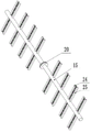
FIG. 1 is a schematic structural diagram of a two-dimensional air flow high-efficiency electric dust collector.
Fig. 2 is a schematic structural diagram of a rapping vibration device in a two-dimensional airflow high-efficiency electric dust collector.
FIG. 3 is a schematic structural diagram of a sweeping ash removal device in a two-dimensional airflow high-efficiency electric dust collector.
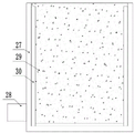
Fig. 4 is a schematic structural diagram of an output device in the two-dimensional airflow high-efficiency electric dust remover.
In the figure: 1. a dust removal cylinder; 2. a first end cover; 3. an air inlet pipe; 4. a cathode discharge wire; 5. a second end cap; 6. an exhaust duct; 7. supporting legs; 8. an anode plate; 9. a cathode plate; 10. a bottom cover; 11. an ash discharge pipe; 12. an output device; 13. placing the plate; 14. a first rotating lever; 15. a second rotating lever; 16. cleaning an ash removal device; 17. knocking the vibrating device; 18. a drive device; 19. a first drive pulley; 20. a second transmission wheel; 21. a side seat; 22. a spring; 23. knocking and hitting the ball; 24. a first sweeper brush; 25. a second cleaning brush; 26. a dust falling port; 27. an output box; 28. a conveying motor; 29. a conveyor belt; 30. a guide plate.
Detailed Description
The preferred embodiments of the present invention will be described in conjunction with the accompanying drawings, and it will be understood that they are described herein for the purpose of illustration and explanation and not limitation.
It should be noted that the terms "center", "upper", "lower", "left", "right", "vertical", "horizontal", "inner", "outer", etc. indicate orientations or positional relationships based on the orientations or positional relationships shown in the drawings, and are only for convenience in describing the present invention and simplifying the description, but do not indicate or imply that the referred devices or elements must have a specific orientation, be constructed in a specific orientation, and be operated, and thus, should not be construed as limiting the present invention.
Example 1
Referring to fig. 1-4, a two-dimensional airflow high-efficiency electric dust collector comprises a dust removing cylinder 1, wherein both ends of the bottom of the dust removing cylinder 1 are fixedly connected with supporting legs 7, the two ends of the dust removing cylinder 1 are respectively fixedly connected with a first end cover 2 and a second end cover 5, one end of the first end cover 2 far away from the dust removing cylinder 1 is fixedly connected with an air inlet pipe 3, one end of the second end cover 5 far away from the dust removing cylinder 1 is fixedly connected with an exhaust pipe 6, a cathode discharge wire 4 is fixedly arranged in the first end cover 2, a plurality of negative plates 9 and anode plates 8 are arranged in the dust removing cylinder 1 in a fixed mode, the outer sides of the negative plates 9 and the anode plates 8 are all provided with a cleaning dust removing device 16, a plurality of dust falling openings 26 are formed in the bottom of the dust removing cylinder 1, the bottom fixed connection bottom cover 10 of the dust removing cylinder 1, the bottom fixed connection dust discharging pipe 11 of the bottom cover 10, the bottom fixed connection output device 12 of the dust discharging pipe 11 is arranged, and a knocking vibration device 17 is arranged in the bottom cover 10.
The top of negative plate 9 and the top fixed connection of dust removal section of thick bamboo 1, the bottom fixed connection of positive plate 8 and dust removal section of thick bamboo 1, and negative plate 9 and positive plate 8 crisscross the setting in dust removal section of thick bamboo 1.
The first sweeper brush 24, the second sweeper brush 25 and the second rotatable shaft 15 are all made of insulating materials.
The rapping vibration device 17 comprises a first rotating rod 14, two ends of the first rotating rod 14 are rotatably connected with side seats 21, the two side seats 21 are respectively and fixedly connected with the inner walls of two ends of the bottom cover 10, a spring 22 is fixedly connected to the first rotating rod 14, and one end, far away from the first rotating rod 14, of the spring 22 is fixedly connected with a rapping ball 23.
The top of the dust removing cylinder 1 is fixedly provided with a driving device 18, the driving device 18 comprises a driving motor, an output shaft of the driving motor is coaxially and fixedly connected with a driving wheel, a first rotating rod 14 and a second rotating rod 15 are respectively and fixedly connected with a first driving wheel 19 and a second driving wheel 20, and the driving wheel is in transmission connection with the first driving wheel 19 and the second driving wheel 20.
The section width of the ash falling port 26 is reduced from top to bottom in sequence.
The output device 12 comprises an output box 27, a conveying belt 29 is arranged in the output box 27, a conveying motor 28 for driving the conveying belt 29 is fixedly arranged outside the output box 27, the supporting legs 7 are fixedly connected with the placing plate 13, and the output box 27 is placed on the placing plate 13.
Example 2
Referring to fig. 1 to 4, the other contents of the present embodiment are the same as embodiment 1, except that: guide plates 30 are fixedly connected to two sides in the output box 27, and the guide plates 30 are obliquely arranged. And anti-bonding coatings are arranged on the outer surfaces of the cathode plate 9 and the anode plate 8.
In the implementation process of the invention, air enters from the air inlet pipe 3, is discharged through the cathode discharge wire 4, then passes through the anode plate 8 and the cathode plate 9, dust can be adsorbed, and the driving motor is started to drive the sweeping dust removal device 16 and the beating vibration device 17 to move so as to remove the dust.
According to the invention, the cathode discharge wire 4, the cathode plate 9 and the anode plate 8 are arranged to realize multi-stage adsorption of dust, the dust on the cathode plate 9 and the anode plate 8 can be continuously brushed off by arranging the cleaning dust removal device 16, and the discharge of the dust in the bottom cover 10 can be accelerated by arranging the beating vibration device 17, so that the phenomenon of secondary dust raising caused by excessive dust accumulation is avoided.
Finally, it should be noted that: although the present invention has been described in detail with reference to the foregoing embodiments, it will be apparent to those skilled in the art that changes may be made in the embodiments and/or equivalents thereof without departing from the spirit and scope of the invention. Any modification, equivalent replacement, or improvement made within the spirit and principle of the present invention should be included in the protection scope of the present invention.
Claims (10)
1. The two-dimensional airflow high-efficiency electric dust remover comprises a dust removing cylinder (1), wherein supporting legs (7) are fixedly connected to two ends of the bottom of the dust removing cylinder (1), the two ends of the dust removing cylinder (1) are respectively fixedly connected with a first end cover (2) and a second end cover (5), the first end cover (2) is far away from an air inlet pipe (3) fixedly connected with one end of the dust removing cylinder (1), the second end cover (5) is far away from an exhaust pipe (6) fixedly connected with one end of the dust removing cylinder (1), cathode discharge wires (4) are fixedly arranged in the first end cover (2), a plurality of cathode plates (9) and anode plates (8) are fixedly arranged in the dust removing cylinder (1), the outer sides of the cathode plates (9) and the anode plates (8) are respectively provided with a dust cleaning device (16), a plurality of dust falling ports (26) are formed in the bottom of the dust removing cylinder (1), and a bottom cover (10) is fixedly connected with the bottom of the dust removing cylinder (1), the bottom end of the bottom cover (10) is fixedly connected with an ash discharge pipe (11), the bottom end of the ash discharge pipe (11) is fixedly connected with an output device (12), and a beating vibration device (17) is arranged in the bottom cover (10).
2. The two-dimensional airflow high-efficiency electric dust collector of claim 1, wherein the top end of the cathode plate (9) is fixedly connected with the top of the dust collection cylinder (1), the anode plate (8) is fixedly connected with the bottom end of the dust collection cylinder (1), and the cathode plate (9) and the anode plate (8) are arranged in the dust collection cylinder (1) in a staggered manner.
3. The two-dimensional airflow high-efficiency electric dust collector according to claim 1, wherein the sweeping and ash removing device (16) comprises a second rotating rod (15) penetrating through a plurality of cathode plates (9) and anode plates (8), a first sweeping brush (24) and a second sweeping brush (25) are respectively arranged on two sides of each cathode plate (9) and anode plate (8), and the first sweeping brush (24) and the second sweeping brush (25) are respectively fixedly connected with the second rotating rod (15).
4. The two-dimensional airflow high-efficiency electric dust collector of claim 3, wherein the first cleaning brush (24), the second cleaning brush (25) and the second rotating rod (15) are made of insulating materials.
5. The two-dimensional airflow high-efficiency electric dust collector according to claim 3, wherein the rapping vibration device (17) comprises a first rotating rod (14), two ends of the first rotating rod (14) are rotatably connected with side seats (21), the two side seats (21) are respectively fixedly connected with the inner walls of two ends of the bottom cover (10), a spring (22) is fixedly connected to the first rotating rod (14), and one end of the spring (22) far away from the first rotating rod (14) is fixedly connected with a rapping ball (23).
6. The two-dimensional airflow high-efficiency electric dust collector of claim 5, wherein a driving device (18) is fixedly arranged at the top of the dust collection cylinder (1), the driving device (18) comprises a driving motor, an output shaft of the driving motor is fixedly connected with a driving wheel, a first rotating rod (14) and a second rotating rod (15) are respectively and fixedly connected with a first driving wheel (19) and a second driving wheel (20), and the driving wheel is in transmission connection with the first driving wheel (19) and the second driving wheel (20).
7. The two-dimensional airflow high-efficiency electric dust collector as claimed in claim 1, wherein the cross-sectional width of the ash falling port (26) is reduced from top to bottom.
8. The two-dimensional airflow high-efficiency electric dust collector according to claim 1, wherein the output device (12) comprises an output box (27), a conveying belt (29) is arranged in the output box (27), a conveying motor (28) for driving the conveying belt (29) is fixedly arranged outside the output box (27), the supporting legs (7) are fixedly connected with the placing plate (13), and the output box (27) is arranged on the placing plate (13).
9. The two-dimensional airflow high-efficiency electric dust collector as claimed in claim 8, wherein the guide plates (30) are fixedly connected to two sides in the output box (27), and the guide plates (30) are obliquely arranged.
10. The two-dimensional airflow high-efficiency electric dust collector as claimed in claim 2 or 3, wherein the outer surfaces of the cathode plate (9) and the anode plate (8) are both provided with anti-sticking coating.
Priority Applications (1)
| Application Number | Priority Date | Filing Date | Title |
|---|---|---|---|
| CN202010289362.2A CN111298971A (en) | 2020-04-14 | 2020-04-14 | Two-dimensional airflow high-efficiency electric dust remover |
Applications Claiming Priority (1)
| Application Number | Priority Date | Filing Date | Title |
|---|---|---|---|
| CN202010289362.2A CN111298971A (en) | 2020-04-14 | 2020-04-14 | Two-dimensional airflow high-efficiency electric dust remover |
Publications (1)
| Publication Number | Publication Date |
|---|---|
| CN111298971A true CN111298971A (en) | 2020-06-19 |
Family
ID=71154142
Family Applications (1)
| Application Number | Title | Priority Date | Filing Date |
|---|---|---|---|
| CN202010289362.2A Pending CN111298971A (en) | 2020-04-14 | 2020-04-14 | Two-dimensional airflow high-efficiency electric dust remover |
Country Status (1)
| Country | Link |
|---|---|
| CN (1) | CN111298971A (en) |
Cited By (3)
| Publication number | Priority date | Publication date | Assignee | Title |
|---|---|---|---|---|
| CN115155814A (en) * | 2022-05-26 | 2022-10-11 | 华能国际电力股份有限公司上海石洞口第二电厂 | Prevent grey vortex optimizing device that falls that electrostatic precipitator collapsed |
| CN115555132A (en) * | 2022-10-14 | 2023-01-03 | 张家口市杰星电子科技有限公司 | Self-cleaning oil fume purifier |
| CN117138959A (en) * | 2023-09-27 | 2023-12-01 | 成都中品建设工程有限公司 | Multistage efficient dust removal device and method for civil engineering |
Citations (18)
| Publication number | Priority date | Publication date | Assignee | Title |
|---|---|---|---|---|
| JPS5511042A (en) * | 1978-07-12 | 1980-01-25 | Hitachi Ltd | Charging device |
| US5429669A (en) * | 1994-07-12 | 1995-07-04 | Chang; Chin-Chu | Electrostatic precipitator |
| KR20040012139A (en) * | 2002-08-01 | 2004-02-11 | 주식회사 포스코 | A hammer for rapping a collecting electrode of electrostatic precipitator |
| CN1936489A (en) * | 2005-09-23 | 2007-03-28 | 阿尔斯通技术有限公司 | Drop hammer |
| CN201500581U (en) * | 2009-08-31 | 2010-06-09 | 怡球金属资源再生(中国)股份有限公司 | Novel electrostatic dust removing device |
| CN204746602U (en) * | 2015-07-20 | 2015-11-11 | 谢章钦 | Row's ash is efficient and can avoid secondary to raise electrostatic precipitator of ash |
| CN105363559A (en) * | 2015-12-22 | 2016-03-02 | 重庆松池科技有限公司 | Brush roll dedusting device for negative ion emission rows |
| CN105536996A (en) * | 2016-01-02 | 2016-05-04 | 唐禹豪 | Electric dust removal device |
| CN106475225A (en) * | 2016-10-31 | 2017-03-08 | 三明学院 | Traveling electrode dust remover and its method |
| CN106733198A (en) * | 2016-11-21 | 2017-05-31 | 陈亚军 | A kind of electric field arrangement with automatic clearing function |
| CN106984438A (en) * | 2017-04-12 | 2017-07-28 | 赵萍 | LD type ultra-low concentration discharge electrostatic precipitator |
| CN107051745A (en) * | 2017-06-02 | 2017-08-18 | 盐城市兰丰环境工程科技有限公司 | A kind of electrostatic precipitation airflow-distribution board ash removal equipment for flapping |
| CN206868435U (en) * | 2017-05-04 | 2018-01-12 | 山东蓝博环保设备有限公司 | A kind of two-dimentional air-flow high-efficiency electric dust catcher |
| CN207224372U (en) * | 2017-08-29 | 2018-04-13 | 新金塔集团有限公司 | A kind of anti-block apparatus of chip conveyer |
| CN108372028A (en) * | 2018-03-23 | 2018-08-07 | 艾尼科环保技术(安徽)有限公司 | A kind of coating pole plate of electrostatic precipitator |
| CN109865364A (en) * | 2019-03-15 | 2019-06-11 | 合肥合意环保机电装备制造有限公司 | A kind of dust-extraction unit with multi-direction rapping function |
| CN110142141A (en) * | 2019-06-18 | 2019-08-20 | 王烨 | A kind of power plant's comprehensive rapping apparatus of electrostatic precipitator ash bucket |
| CN210230287U (en) * | 2019-06-29 | 2020-04-03 | 大唐东营发电有限公司 | Ash falling device for flue gas dedusting electrode plate of power plant |
-
2020
- 2020-04-14 CN CN202010289362.2A patent/CN111298971A/en active Pending
Patent Citations (18)
| Publication number | Priority date | Publication date | Assignee | Title |
|---|---|---|---|---|
| JPS5511042A (en) * | 1978-07-12 | 1980-01-25 | Hitachi Ltd | Charging device |
| US5429669A (en) * | 1994-07-12 | 1995-07-04 | Chang; Chin-Chu | Electrostatic precipitator |
| KR20040012139A (en) * | 2002-08-01 | 2004-02-11 | 주식회사 포스코 | A hammer for rapping a collecting electrode of electrostatic precipitator |
| CN1936489A (en) * | 2005-09-23 | 2007-03-28 | 阿尔斯通技术有限公司 | Drop hammer |
| CN201500581U (en) * | 2009-08-31 | 2010-06-09 | 怡球金属资源再生(中国)股份有限公司 | Novel electrostatic dust removing device |
| CN204746602U (en) * | 2015-07-20 | 2015-11-11 | 谢章钦 | Row's ash is efficient and can avoid secondary to raise electrostatic precipitator of ash |
| CN105363559A (en) * | 2015-12-22 | 2016-03-02 | 重庆松池科技有限公司 | Brush roll dedusting device for negative ion emission rows |
| CN105536996A (en) * | 2016-01-02 | 2016-05-04 | 唐禹豪 | Electric dust removal device |
| CN106475225A (en) * | 2016-10-31 | 2017-03-08 | 三明学院 | Traveling electrode dust remover and its method |
| CN106733198A (en) * | 2016-11-21 | 2017-05-31 | 陈亚军 | A kind of electric field arrangement with automatic clearing function |
| CN106984438A (en) * | 2017-04-12 | 2017-07-28 | 赵萍 | LD type ultra-low concentration discharge electrostatic precipitator |
| CN206868435U (en) * | 2017-05-04 | 2018-01-12 | 山东蓝博环保设备有限公司 | A kind of two-dimentional air-flow high-efficiency electric dust catcher |
| CN107051745A (en) * | 2017-06-02 | 2017-08-18 | 盐城市兰丰环境工程科技有限公司 | A kind of electrostatic precipitation airflow-distribution board ash removal equipment for flapping |
| CN207224372U (en) * | 2017-08-29 | 2018-04-13 | 新金塔集团有限公司 | A kind of anti-block apparatus of chip conveyer |
| CN108372028A (en) * | 2018-03-23 | 2018-08-07 | 艾尼科环保技术(安徽)有限公司 | A kind of coating pole plate of electrostatic precipitator |
| CN109865364A (en) * | 2019-03-15 | 2019-06-11 | 合肥合意环保机电装备制造有限公司 | A kind of dust-extraction unit with multi-direction rapping function |
| CN110142141A (en) * | 2019-06-18 | 2019-08-20 | 王烨 | A kind of power plant's comprehensive rapping apparatus of electrostatic precipitator ash bucket |
| CN210230287U (en) * | 2019-06-29 | 2020-04-03 | 大唐东营发电有限公司 | Ash falling device for flue gas dedusting electrode plate of power plant |
Cited By (4)
| Publication number | Priority date | Publication date | Assignee | Title |
|---|---|---|---|---|
| CN115155814A (en) * | 2022-05-26 | 2022-10-11 | 华能国际电力股份有限公司上海石洞口第二电厂 | Prevent grey vortex optimizing device that falls that electrostatic precipitator collapsed |
| CN115555132A (en) * | 2022-10-14 | 2023-01-03 | 张家口市杰星电子科技有限公司 | Self-cleaning oil fume purifier |
| CN117138959A (en) * | 2023-09-27 | 2023-12-01 | 成都中品建设工程有限公司 | Multistage efficient dust removal device and method for civil engineering |
| CN117138959B (en) * | 2023-09-27 | 2024-02-27 | 成都中品建设工程有限公司 | Multistage efficient dust removal device and method for civil engineering |
Similar Documents
| Publication | Publication Date | Title |
|---|---|---|
| CN111298971A (en) | Two-dimensional airflow high-efficiency electric dust remover | |
| CN101690913A (en) | Reversible rotary anode type electric dust remover | |
| CN110425848A (en) | A kind of aqueous coal drying dedusting integrated device | |
| CN105855056A (en) | Micro-unit crossflow type anode device of electric precipitator | |
| CN207994357U (en) | It is a kind of electrically to use forceful electric power power distribution cabinet dust-extraction unit | |
| CN206868435U (en) | A kind of two-dimentional air-flow high-efficiency electric dust catcher | |
| CN201154325Y (en) | Heat-exchange electric dust remover | |
| CN107456813B (en) | air filtering and dust removing device for blast furnace blower | |
| CN206778713U (en) | Mobile Elex precipitator | |
| CN202570381U (en) | Composite high-voltage electrostatic dust collector system | |
| CN101708486B (en) | Brushing type groove-shaped plate dust repurifying device for electric dust collector | |
| CN206027925U (en) | Compound minimum discharge electrostatic precipitator | |
| CN217550070U (en) | High-efficient deashing electrostatic precipitator | |
| CN202590963U (en) | Energy-saving electrical dust precipitator | |
| CN208098384U (en) | A kind of wide space ESP | |
| CN205797497U (en) | Electric cleaner micro unit cross-flow type anode assembly | |
| CN205128191U (en) | Take secondary dust collector's electrostatic precipitator | |
| CN201572680U (en) | Brushable trough plate dust repurification device for electric precipitator | |
| CN204710556U (en) | New type wet electric cleaner | |
| CN202292940U (en) | Woodiness dust cyclone electrostatic precipitator | |
| CN201482562U (en) | Reversible anode type electric dust collector | |
| CN208161838U (en) | A kind of wet static dedusting device | |
| CN208694594U (en) | A kind of electric-bag complex dust collector of high-efficiency low-resistance | |
| CN202199548U (en) | High-voltage electrostatic dust collector with movable dust collecting electrode plates | |
| CN108405183B (en) | High-voltage electrostatic dust collector |
Legal Events
| Date | Code | Title | Description |
|---|---|---|---|
| PB01 | Publication | ||
| PB01 | Publication | ||
| SE01 | Entry into force of request for substantive examination | ||
| SE01 | Entry into force of request for substantive examination | ||
| RJ01 | Rejection of invention patent application after publication | ||
| RJ01 | Rejection of invention patent application after publication |
Application publication date: 20200619 |