CN111277214A - Photovoltaic module installation system convenient to upset photovoltaic module - Google Patents
Photovoltaic module installation system convenient to upset photovoltaic module Download PDFInfo
- Publication number
- CN111277214A CN111277214A CN202010153866.1A CN202010153866A CN111277214A CN 111277214 A CN111277214 A CN 111277214A CN 202010153866 A CN202010153866 A CN 202010153866A CN 111277214 A CN111277214 A CN 111277214A
- Authority
- CN
- China
- Prior art keywords
- frame
- photovoltaic module
- photovoltaic
- photovoltaic panel
- propulsion device
- Prior art date
- Legal status (The legal status is an assumption and is not a legal conclusion. Google has not performed a legal analysis and makes no representation as to the accuracy of the status listed.)
- Withdrawn
Links
- 238000009434 installation Methods 0.000 title abstract description 27
- 230000007246 mechanism Effects 0.000 claims abstract description 30
- 230000003139 buffering effect Effects 0.000 claims abstract description 8
- 238000003466 welding Methods 0.000 claims description 3
- 230000000149 penetrating effect Effects 0.000 claims description 2
- 235000017166 Bambusa arundinacea Nutrition 0.000 claims 3
- 235000017491 Bambusa tulda Nutrition 0.000 claims 3
- 241001330002 Bambuseae Species 0.000 claims 3
- 235000015334 Phyllostachys viridis Nutrition 0.000 claims 3
- 239000011425 bamboo Substances 0.000 claims 3
- 230000000694 effects Effects 0.000 abstract description 7
- 230000002035 prolonged effect Effects 0.000 abstract description 4
- 238000000034 method Methods 0.000 abstract description 3
- 230000008569 process Effects 0.000 abstract description 3
- 230000006872 improvement Effects 0.000 description 12
- 238000005286 illumination Methods 0.000 description 9
- 230000007306 turnover Effects 0.000 description 3
- 230000009471 action Effects 0.000 description 2
- 238000013016 damping Methods 0.000 description 2
- 230000007547 defect Effects 0.000 description 2
- 238000006073 displacement reaction Methods 0.000 description 2
- 230000005611 electricity Effects 0.000 description 1
- 230000004048 modification Effects 0.000 description 1
- 238000012986 modification Methods 0.000 description 1
- 238000010248 power generation Methods 0.000 description 1
- 238000003825 pressing Methods 0.000 description 1
- 238000004904 shortening Methods 0.000 description 1
- 238000003860 storage Methods 0.000 description 1
Images


Classifications
-
- H—ELECTRICITY
- H02—GENERATION; CONVERSION OR DISTRIBUTION OF ELECTRIC POWER
- H02S—GENERATION OF ELECTRIC POWER BY CONVERSION OF INFRARED RADIATION, VISIBLE LIGHT OR ULTRAVIOLET LIGHT, e.g. USING PHOTOVOLTAIC [PV] MODULES
- H02S20/00—Supporting structures for PV modules
- H02S20/30—Supporting structures being movable or adjustable, e.g. for angle adjustment
- H02S20/32—Supporting structures being movable or adjustable, e.g. for angle adjustment specially adapted for solar tracking
-
- F—MECHANICAL ENGINEERING; LIGHTING; HEATING; WEAPONS; BLASTING
- F24—HEATING; RANGES; VENTILATING
- F24S—SOLAR HEAT COLLECTORS; SOLAR HEAT SYSTEMS
- F24S25/00—Arrangement of stationary mountings or supports for solar heat collector modules
- F24S25/20—Peripheral frames for modules
-
- F—MECHANICAL ENGINEERING; LIGHTING; HEATING; WEAPONS; BLASTING
- F24—HEATING; RANGES; VENTILATING
- F24S—SOLAR HEAT COLLECTORS; SOLAR HEAT SYSTEMS
- F24S30/00—Arrangements for moving or orienting solar heat collector modules
- F24S30/40—Arrangements for moving or orienting solar heat collector modules for rotary movement
- F24S30/42—Arrangements for moving or orienting solar heat collector modules for rotary movement with only one rotation axis
- F24S30/425—Horizontal axis
-
- H—ELECTRICITY
- H02—GENERATION; CONVERSION OR DISTRIBUTION OF ELECTRIC POWER
- H02S—GENERATION OF ELECTRIC POWER BY CONVERSION OF INFRARED RADIATION, VISIBLE LIGHT OR ULTRAVIOLET LIGHT, e.g. USING PHOTOVOLTAIC [PV] MODULES
- H02S30/00—Structural details of PV modules other than those related to light conversion
- H02S30/10—Frame structures
-
- Y—GENERAL TAGGING OF NEW TECHNOLOGICAL DEVELOPMENTS; GENERAL TAGGING OF CROSS-SECTIONAL TECHNOLOGIES SPANNING OVER SEVERAL SECTIONS OF THE IPC; TECHNICAL SUBJECTS COVERED BY FORMER USPC CROSS-REFERENCE ART COLLECTIONS [XRACs] AND DIGESTS
- Y02—TECHNOLOGIES OR APPLICATIONS FOR MITIGATION OR ADAPTATION AGAINST CLIMATE CHANGE
- Y02E—REDUCTION OF GREENHOUSE GAS [GHG] EMISSIONS, RELATED TO ENERGY GENERATION, TRANSMISSION OR DISTRIBUTION
- Y02E10/00—Energy generation through renewable energy sources
- Y02E10/40—Solar thermal energy, e.g. solar towers
- Y02E10/47—Mountings or tracking
-
- Y—GENERAL TAGGING OF NEW TECHNOLOGICAL DEVELOPMENTS; GENERAL TAGGING OF CROSS-SECTIONAL TECHNOLOGIES SPANNING OVER SEVERAL SECTIONS OF THE IPC; TECHNICAL SUBJECTS COVERED BY FORMER USPC CROSS-REFERENCE ART COLLECTIONS [XRACs] AND DIGESTS
- Y02—TECHNOLOGIES OR APPLICATIONS FOR MITIGATION OR ADAPTATION AGAINST CLIMATE CHANGE
- Y02E—REDUCTION OF GREENHOUSE GAS [GHG] EMISSIONS, RELATED TO ENERGY GENERATION, TRANSMISSION OR DISTRIBUTION
- Y02E10/00—Energy generation through renewable energy sources
- Y02E10/50—Photovoltaic [PV] energy
Abstract
The invention relates to the technical field of photovoltaic module installation, in particular to a photovoltaic module installation system convenient for turning over a photovoltaic module, which comprises a photovoltaic panel installation frame, an L-shaped fixing frame and an installation bottom plate, wherein the photovoltaic panel installation frame is fixed on an inclined plane of the L-shaped fixing frame; the photovoltaic panel mounting frame integrally rotates along with the L-shaped fixing frame, and the whole photovoltaic panel can be effectively prevented from being impacted due to the inertia effect through the buffering effect of the first buffering mechanism and the second buffering mechanism in the rotating process, so that the safety performance of the photovoltaic panel mounting frame is greatly improved, and the service life of the photovoltaic panel mounting frame is prolonged.
Description
Technical Field
The invention relates to the technical field of photovoltaic module installation, in particular to a photovoltaic module installation system convenient for turning over a photovoltaic module.
Background
Solar photovoltaic power generation is a green energy, utilizes the sunlight to send clean energy for the people, and photovoltaic module's installing support supports photovoltaic module for photovoltaic module surface is to the sun, thereby generates electricity, and photovoltaic module is installed on the roof usually. Due to different time periods, the irradiation angles of sunlight are different, and if the illumination receiving time of the photovoltaic panel is prolonged, the photovoltaic module needs to be turned over.
The utility model with the patent number of CN209676165U discloses a photovoltaic module installation system convenient for turning over a photovoltaic module, which comprises a left support plate, a right support plate and an installation frame, wherein the left support plate and the right support plate are connected to form an inverted V-shaped support; although the photovoltaic module mounting system of the turnover photovoltaic module can turn over the mounted photovoltaic module to enable the surface of the photovoltaic module to face the sun, so that the utilization rate of the photovoltaic module to sunlight is improved, when the photovoltaic module is turned over along with the mounting frame, the photovoltaic module is easy to damage due to the fact that impact is easy to occur between the photovoltaic module and the support under the action of inertia; in addition, this photovoltaic module needs personnel to overturn it, and its practicality is relatively poor. Therefore, aiming at the defects of the existing photovoltaic module installation system for overturning the photovoltaic module, the photovoltaic module installation system which can reduce the impact on the photovoltaic module during overturning and can automatically overturn according to the illumination time period is designed.
Disclosure of Invention
The invention aims to solve the technical problem of designing a photovoltaic module installation system convenient for turning over a photovoltaic module so as to solve the defects that the existing photovoltaic module is subjected to larger impact force when being turned over along with an installation frame and cannot be automatically turned over according to an illumination time period.
The invention is realized by the following technical scheme:
a photovoltaic module mounting system convenient for turning over a photovoltaic module comprises a photovoltaic panel mounting frame, an L-shaped fixing frame and a mounting base plate, wherein the photovoltaic panel mounting frame is fixed on an inclined plane of the L-shaped fixing frame, fixing blocks are arranged at the left end and the right end of the upper surface of the mounting base plate, a plurality of sliding rods are arranged between the two fixing blocks, a sliding block is arranged on the upper surface of the mounting base plate between the two fixing blocks, a sliding hole capable of penetrating through the sliding rod is formed in the sliding block, an electric propulsion device is arranged on the inner side surface of one of the fixing blocks, and the extension end of the electric propulsion device is connected with the sliding block;
the L-shaped fixing frame comprises a vertical frame and a horizontal frame, a first rotating piece is arranged on the lower surface of the joint of the vertical frame and the horizontal frame, the lower surface of the first rotating piece is connected with the sliding block, the L-shaped fixing frame is rotatably connected with the upper surface of the sliding block through the first rotating piece, a second rotating piece is fixed at the upper end of the vertical frame, a third rotating piece is arranged on the upper surface of a fixed block connected with the electric propulsion device, a movable rod is connected between the third rotating piece and the second rotating piece, a first buffer mechanism is connected on the rear side surface of the upper end of the vertical frame, a second buffer mechanism is connected on the lower surface of the right end of the horizontal frame, the first buffer mechanism and the second buffer mechanism respectively comprise a batten, inserting barrels, buffer springs and connecting inserting rods, the two inserting barrels are fixed at two ends of the upper surface of the batten, and the buffer springs are connected on the, the lower end of the connecting inserted bar extends into the inserting cylinder and is connected with the upper end of the buffer spring, and the upper end of the connecting inserted bar is connected with the vertical frame or the horizontal frame.
As a further improvement of the scheme, a light intensity sensor is arranged at the top end of the outer surface of the photovoltaic panel mounting frame, a controller is arranged on the bottom surface of the photovoltaic panel mounting frame, the light intensity sensor is connected with a signal input end of the controller, and the electric propulsion device is connected with a signal output end of the controller.
As a further improvement of the above scheme, a rectangular mounting groove is formed in the upper surface of the photovoltaic panel mounting frame, blank holder grooves are formed in four outer sides of the rectangular mounting groove, a blank holder frame is arranged on each blank holder groove, a plurality of corresponding mounting holes are uniformly formed in each blank holder frame and each blank holder groove, and fixing screws are arranged on the mounting holes.
As a further improvement of the scheme, the upper end of the vertical frame and the right end of the horizontal frame are both provided with wedge-shaped bar blocks, the photovoltaic panel installation frame is clamped between the two wedge-shaped bar blocks, and the photovoltaic panel installation frame is welded with the wedge-shaped bar blocks.
As a further improvement of the scheme, two sliding rods are arranged between the two fixed blocks, and the electric propulsion device is arranged between the two sliding rods.
As a further improvement of the above scheme, the two first buffer mechanisms on the vertical frame are respectively arranged at the front end and the rear end of the rear side surface of the upper end of the vertical frame, and the two second buffer mechanisms on the horizontal frame are also respectively arranged at the front end and the rear end of the lower surface of the horizontal frame.
As a further improvement of the scheme, the lower surface of the batten is provided with a rubber pad.
As a further improvement of the above scheme, the electric propulsion device is one of an electric telescopic rod, a hydraulic cylinder or an air cylinder.
Has the advantages that:
1. compared with the prior art, the whole L-shaped fixing frame can rotate back and forth by 90 degrees under the action of the movable rod by moving the sliding block left and right along the sliding rod through the extension or shortening of the electric propulsion device, so that the photovoltaic panel arranged on the L-shaped fixing frame can receive illumination in all directions, the illumination time of the photovoltaic panel is greatly prolonged, and the utilization rate of the photovoltaic module to sunlight is improved; in addition, the photovoltaic panel mounting frame integrally rotates along with the L-shaped fixing frame, and the whole photovoltaic panel can be effectively prevented from being impacted due to the inertia effect through the buffering effect of the first buffering mechanism and the second buffering mechanism in the rotating process, so that the safety performance of the photovoltaic panel mounting frame is greatly improved, and the service life of the photovoltaic panel mounting frame is prolonged.
2. The photovoltaic panel installation frame is characterized in that the top end of the outer surface of the photovoltaic panel installation frame is provided with a light intensity sensor, when light irradiates the back surface of the photovoltaic panel, the light intensity sensor is low in illumination intensity, so that a signal is sent to the controller, the controller controls the electric propulsion device to extend, the photovoltaic panel automatically turns over for 90 degrees to continuously receive illumination, the automation degree is high, the photovoltaic panel does not need to be turned over manually, and the photovoltaic panel installation frame is good in practicability.
Drawings
In order to more clearly illustrate the technical solutions of the embodiments of the present invention, the drawings used in the description of the embodiments will be briefly introduced below, and it is obvious that the drawings in the following description are only some embodiments of the present invention, and it is obvious for those skilled in the art that other drawings can be obtained according to the drawings without creative efforts.
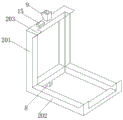
FIG. 1 is a first angular perspective view of the present invention;
FIG. 2 is a second angular perspective view of the present invention;
FIG. 3 is a perspective view of an L-shaped fixing frame according to the present invention;
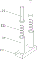
FIG. 4 is an exploded view of the first damping mechanism or the second damping mechanism of the present invention;
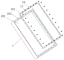
fig. 5 is an exploded view of the photovoltaic panel mounting frame according to the present invention.
The photovoltaic panel mounting frame comprises a photovoltaic panel mounting frame 1, a 2-L-shaped fixing frame 3, a mounting bottom plate 4, a fixing block 5, a sliding rod 6, a sliding block 7, an electric propulsion device 8, a first rotating piece 9, a second rotating piece 10, a third rotating piece 11, a movable rod 12, a first buffer mechanism 13, a second buffer mechanism 15, a light intensity sensor 16, a pressing frame 17 and a fixing screw;
101-rectangular mounting groove, 102-blank holder groove;
201-vertical frame, 202-horizontal frame, 203-wedge-shaped bar block;
121-lath, 122-inserting cylinder, 123-buffer spring and 124-connecting inserting rod;
161-mounting holes.
Detailed Description
In order to make the technical solutions better understood by those skilled in the art, the technical solutions in the embodiments of the present application will be clearly and completely described below with reference to the drawings in the embodiments of the present application, and it is obvious that the described embodiments are only partial embodiments of the present application, but not all embodiments. All other embodiments, which can be derived by a person skilled in the art from the embodiments given herein without making any creative effort, shall fall within the protection scope of the present application.
Example 1
The L-shaped fixing frame 2 is specifically described below, and includes a vertical frame 201 and a horizontal frame 202, a first rotating member 8 is disposed on a lower surface of a joint of the vertical frame 201 and the horizontal frame 202, the lower surface of the first rotating member 8 is connected with the slider 5, the L-shaped fixing frame 2 is rotatably connected with an upper surface of the slider 5 through the first rotating member 8, a second rotating member 9 is fixed on an upper end of the vertical frame 201, a third rotating member 10 is disposed on an upper surface of the fixing block 4 connected with the electric propulsion device 7, a movable rod 11 is connected between the third rotating member 10 and the second rotating member 9, a first buffer mechanism 12 is connected to a rear side surface of an upper end of the vertical frame 201, and the two first buffer mechanisms 12 are disposed at front and rear ends of the rear side surface of the upper end of the. The lower surface of the right end of the horizontal frame 202 is connected with two second buffer mechanisms 13, and the two second buffer mechanisms 13 are respectively arranged at the front end and the rear end of the surface of the horizontal frame 202.
The first buffer mechanism 12 and the second buffer mechanism 13 in this embodiment 1 each include a slat 121, two inserting cylinders 122, a buffer spring 123 and a connecting plunger 124, the two inserting cylinders 122 are fixed at two ends of the upper surface of the slat 121, the buffer spring 123 is connected on the bottom wall of the inner cavity of the inserting cylinder 122, the lower end of the connecting plunger 124 extends into the inserting cylinder 122 and is connected with the upper end of the buffer spring 123, and the upper end of the connecting plunger 124 is connected with the vertical frame 201 or the horizontal frame 202. In addition, in order to prevent the upper surface of the installation bottom plate 3 from being scratched when the slat 121 falls down, a rubber pad (not shown) is further provided on the lower surface of the slat 121.
Photovoltaic board installing frame 1 in this embodiment 1 has also carried out certain improvement, rectangle mounting groove 101 has mainly been seted up at photovoltaic board installing frame 1's upper surface to it, blank holder groove 102 has been seted up to four outsides that are located rectangle mounting groove 101, be provided with on the blank holder groove 102 and press frame 16, evenly set up a plurality of mounting holes 161 that correspond on blank holder frame 16 and the blank holder groove 16, be provided with fixed screw 17 on the mounting hole 161, the connection effect through press frame 16 and fixed screw 17 can be with photovoltaic board stable installation in photovoltaic board installing frame 1.
Finally, what needs to be described is a specific connection mode of the L-shaped fixing frame 2 and the installation bottom plate 3, the upper end of the vertical frame 201 and the right end of the horizontal frame 201 are both provided with the wedge-shaped bars 203, the photovoltaic panel installation frame 1 is clamped between the two wedge-shaped bars 203, and the photovoltaic panel installation frame 1 is welded with the wedge-shaped bars 203. The L-shaped fixing frame 2 and the mounting base plate 3 can be stably connected by the above-described engagement and welding.
Example 2
The L-shaped fixing frame 2 is specifically described below, and includes a vertical frame 201 and a horizontal frame 202, a first rotating member 8 is disposed on a lower surface of a joint of the vertical frame 201 and the horizontal frame 202, the lower surface of the first rotating member 8 is connected with the slider 5, the L-shaped fixing frame 2 is rotatably connected with an upper surface of the slider 5 through the first rotating member 8, a second rotating member 9 is fixed on an upper end of the vertical frame 201, a third rotating member 10 is disposed on an upper surface of the fixing block 4 connected with the electric propulsion device 7, a movable rod 11 is connected between the third rotating member 10 and the second rotating member 9, a first buffer mechanism 12 is connected to a rear side surface of an upper end of the vertical frame 201, and the two first buffer mechanisms 12 are disposed at front and rear ends of the rear side surface of the upper end of the. The lower surface of the right end of the horizontal frame 202 is connected with two second buffer mechanisms 13, and the two second buffer mechanisms 13 are respectively arranged at the front end and the rear end of the surface of the horizontal frame 202.
The first buffer mechanism 12 and the second buffer mechanism 13 in this embodiment 2 each include a slat 121, two inserting cylinders 122, a buffer spring 123 and a connecting plunger 124, the two inserting cylinders 122 are fixed at two ends of the upper surface of the slat 121, the buffer spring 123 is connected on the bottom wall of the inner cavity of the inserting cylinder 122, the lower end of the connecting plunger 124 extends into the inserting cylinder 122 and is connected with the upper end of the buffer spring 123, and the upper end of the connecting plunger 124 is connected with the vertical frame 201 or the horizontal frame 202. In addition, in order to prevent the upper surface of the installation bottom plate 3 from being scratched when the slat 121 falls down, a rubber pad (not shown) is further provided on the lower surface of the slat 121.
Photovoltaic board installing frame 1 in this embodiment 2 has also carried out certain improvement, rectangle mounting groove 101 has mainly been seted up at photovoltaic board installing frame 1's upper surface to it, blank holder groove 102 has been seted up to four outsides that are located rectangle mounting groove 101, be provided with on the blank holder groove 102 and press frame 16, evenly set up a plurality of mounting holes 161 that correspond on blank holder frame 16 and the blank holder groove 16, be provided with fixed screw 17 on the mounting hole 161, the connection effect through press frame 16 and fixed screw 17 can be with photovoltaic board stable installation in photovoltaic board installing frame 1. In the specific connection mode of the L-shaped fixing frame 2 and the mounting base plate 3 in this embodiment, the wedge-shaped bar blocks 203 are arranged at the upper end of the vertical frame 201 and the right end of the horizontal frame 201, and the photovoltaic panel mounting frame 1 is clamped between the two wedge-shaped bar blocks 203 and welded with the photovoltaic panel mounting frame 1 and the wedge-shaped bar blocks 203. The L-shaped fixing frame 2 and the mounting base plate 3 can be stably connected by the above-described engagement and welding.
The main improvement point is that a light intensity sensor 15 is arranged at the top end of the outer surface of the photovoltaic panel mounting frame 1, a controller (not shown in the figure) is arranged on the bottom surface of the photovoltaic panel mounting frame 1, a storage battery for supplying power (supplying power through the photovoltaic panel) is arranged, the light intensity sensor 15 is connected with a signal input end of the controller, and then the electric propulsion device 7 is connected with a signal output end of the controller. When light is irradiated on the back of the photovoltaic panel mounting frame 1, the light intensity received by the light intensity sensor 15 is weak, so that a signal is sent to the controller, the controller controls the electric propulsion device 7 to extend, and the whole photovoltaic panel mounting frame 1 and the L-shaped fixing frame 2 are turned for 90 degrees to receive illumination. The whole overturning process does not need manual operation, and the effect is better.
The above description is only for the purpose of illustrating the preferred embodiments of the present invention and is not to be construed as limiting the invention, and any modifications, equivalents and improvements made within the spirit and principle of the present invention are intended to be included within the scope of the present invention.
Claims (8)
1. The photovoltaic module mounting system convenient for turning over a photovoltaic module comprises a photovoltaic panel mounting frame (1), an L-shaped fixing frame (2) and a mounting base plate (3), wherein the photovoltaic panel mounting frame (1) is fixed on an inclined plane of the L-shaped fixing frame (2), and is characterized in that fixed blocks (4) are arranged at the left end and the right end of the upper surface of the mounting base plate (3), slide rods (5) are arranged between the two fixed blocks (4), a slide block (6) is arranged on the upper surface of the mounting base plate between the two fixed blocks (4), slide holes capable of penetrating through the slide rods (5) are formed in the slide block (6), an electric propulsion device (7) is arranged on the inner side surface of one fixed block (4), and the extension end of the electric propulsion device (7) is connected with the slide block (6);
the L-shaped fixing frame (2) comprises a vertical frame (201) and a horizontal frame (202), a first rotating piece (8) is arranged on the lower surface of the joint of the vertical frame (201) and the horizontal frame (202), the lower surface of the first rotating piece (8) is connected with a sliding block (5), the L-shaped fixing frame (2) is rotatably connected with the upper surface of the sliding block (5) through the first rotating piece (8), a second rotating piece (9) is fixed at the upper end of the vertical frame (201), a third rotating piece (10) is arranged on the upper surface of a fixing block (4) connected with an electric propulsion device (7), a movable rod (11) is connected between the third rotating piece (10) and the second rotating piece (9), a first buffering mechanism (12) is connected on the rear side surface of the upper end of the vertical frame (201), a second buffering mechanism (13) is connected on the lower surface of the right end of the horizontal frame (202), first buffer gear (12) and second buffer gear (13) all include slat (121), a section of thick bamboo (122), buffer spring (123) and connect inserted bar (124), two inserted cylinder (122) are fixed at the upper surface both ends of slat (121), buffer spring (123) are connected on the inner chamber diapire of a section of thick bamboo (122), the lower extreme of connecting inserted bar (124) is stretched into and is connected with the upper end of buffer spring (123) in a section of thick bamboo (122), the upper end of connecting inserted bar (124) is connected with vertical frame (201) or horizontal stand (202).
2. The photovoltaic module mounting system for facilitating the flipping of a photovoltaic module of claim 1, wherein: the photovoltaic panel installing frame is characterized in that a light intensity sensor (15) is arranged at the top end of the outer surface of the photovoltaic panel installing frame (1), a controller is arranged on the bottom surface of the photovoltaic panel installing frame (1), the light intensity sensor (15) is connected with a signal input end of the controller, and the electric propulsion device (7) is connected with a signal output end of the controller.
3. The photovoltaic module mounting system for facilitating the flipping of a photovoltaic module of claim 1, wherein: the photovoltaic panel installing frame is characterized in that a rectangular installing groove (101) is formed in the upper surface of the photovoltaic panel installing frame (1), blank holder grooves (102) are formed in four outer edges of the rectangular installing groove (101), a blank holder frame (16) is arranged on the blank holder grooves (102), a plurality of corresponding installing holes (161) are uniformly formed in the blank holder frame (16) and the blank holder frame grooves (16), and fixing screws (17) are arranged on the installing holes (161).
4. The photovoltaic module mounting system for facilitating the flipping of a photovoltaic module of claim 1, wherein: the upper end of vertical frame (201) and the right-hand member of horizontal rack (202) all are provided with wedge strip piece (203), photovoltaic board installing frame (1) card is gone into between two wedge strip pieces (203) to with photovoltaic board installing frame (1) and wedge strip piece (203) welding.
5. The photovoltaic module mounting system for facilitating the flipping of a photovoltaic module of claim 1, wherein: two sliding rods (5) between the two fixed blocks (4) are arranged, and an electric propulsion device (7) is arranged between the two sliding rods (5).
6. The photovoltaic module mounting system for facilitating the flipping of a photovoltaic module of claim 1, wherein: the two first buffer mechanisms (12) on the vertical frame (201) are respectively arranged at the front end and the rear end of the rear side surface of the upper end of the vertical frame, and the two second buffer mechanisms (13) on the horizontal frame (202) are also respectively arranged at the front end and the rear end of the lower surface of the horizontal frame.
7. The photovoltaic module mounting system for facilitating the flipping of a photovoltaic module of claim 1, wherein: the lower surface of the lath (121) is provided with a rubber pad.
8. The photovoltaic module mounting system for facilitating the flipping of a photovoltaic module of claim 1, wherein: the electric propulsion device (7) is one of an electric telescopic rod, a hydraulic cylinder or an air cylinder.
Priority Applications (1)
| Application Number | Priority Date | Filing Date | Title |
|---|---|---|---|
| CN202010153866.1A CN111277214A (en) | 2020-03-07 | 2020-03-07 | Photovoltaic module installation system convenient to upset photovoltaic module |
Applications Claiming Priority (1)
| Application Number | Priority Date | Filing Date | Title |
|---|---|---|---|
| CN202010153866.1A CN111277214A (en) | 2020-03-07 | 2020-03-07 | Photovoltaic module installation system convenient to upset photovoltaic module |
Publications (1)
| Publication Number | Publication Date |
|---|---|
| CN111277214A true CN111277214A (en) | 2020-06-12 |
Family
ID=71000539
Family Applications (1)
| Application Number | Title | Priority Date | Filing Date |
|---|---|---|---|
| CN202010153866.1A Withdrawn CN111277214A (en) | 2020-03-07 | 2020-03-07 | Photovoltaic module installation system convenient to upset photovoltaic module |
Country Status (1)
| Country | Link |
|---|---|
| CN (1) | CN111277214A (en) |
Cited By (2)
| Publication number | Priority date | Publication date | Assignee | Title |
|---|---|---|---|---|
| CN113992136A (en) * | 2021-11-19 | 2022-01-28 | 中国电建集团贵阳勘测设计研究院有限公司 | Construction device for photovoltaic power station |
| CN115276557A (en) * | 2022-06-24 | 2022-11-01 | 广东奥飞新能源有限公司 | Distributed photovoltaic measurement device capable of being connected to power grid and use method thereof |
-
2020
- 2020-03-07 CN CN202010153866.1A patent/CN111277214A/en not_active Withdrawn
Cited By (4)
| Publication number | Priority date | Publication date | Assignee | Title |
|---|---|---|---|---|
| CN113992136A (en) * | 2021-11-19 | 2022-01-28 | 中国电建集团贵阳勘测设计研究院有限公司 | Construction device for photovoltaic power station |
| CN113992136B (en) * | 2021-11-19 | 2023-11-28 | 中国电建集团贵阳勘测设计研究院有限公司 | Construction device for photovoltaic power station |
| CN115276557A (en) * | 2022-06-24 | 2022-11-01 | 广东奥飞新能源有限公司 | Distributed photovoltaic measurement device capable of being connected to power grid and use method thereof |
| CN115276557B (en) * | 2022-06-24 | 2023-09-26 | 广东奥飞新能源有限公司 | Distributed photovoltaic measurement device capable of being connected into power grid and application method thereof |
Similar Documents
| Publication | Publication Date | Title |
|---|---|---|
| CN207732696U (en) | A kind of adjustable solar-cell panel mounting device | |
| CN111277214A (en) | Photovoltaic module installation system convenient to upset photovoltaic module | |
| CN211959135U (en) | Building device is built in energy-concerving and environment-protective type room | |
| CN216414231U (en) | Solar photovoltaic power generation and energy storage integrated device | |
| CN111464129A (en) | Automatic folding device of solar panel | |
| CN209389991U (en) | A kind of multifuctional solar bracket | |
| CN215734152U (en) | Photovoltaic board installing support with adjustable equipment | |
| CN213027923U (en) | Photovoltaic power generation device of easy installation | |
| CN213709871U (en) | Box-type house with solar power generation function | |
| CN209982402U (en) | Solar photovoltaic power generation board installation device | |
| CN210050713U (en) | Solar street lamp with good use effect | |
| CN209627292U (en) | It is a kind of be conveniently adjusted and can stable holding solar battery board mounting stand | |
| CN219394764U (en) | Angle-adjustable solar photovoltaic power generation panel bracket | |
| CN211519251U (en) | A solar panel fixing device for new energy automobile | |
| CN212518858U (en) | Grounding connection structure of photovoltaic panel | |
| CN220401651U (en) | Curtain wall type solar photovoltaic group system | |
| CN218335868U (en) | Photovoltaic board locating support that anti-wind performance is strong | |
| CN218734041U (en) | Solar photovoltaic support convenient to installation | |
| CN209994154U (en) | Aluminum support for fixing outdoor communication box | |
| CN220190752U (en) | Photovoltaic module structure | |
| CN215336094U (en) | LED street lamp with high-efficiency photoelectric conversion | |
| CN219287448U (en) | Mounting bracket for photovoltaic module | |
| CN212178750U (en) | Height-adjustable's solar energy post lamp | |
| CN213778215U (en) | Solar heat collector convenient for angle adjustment | |
| CN211830667U (en) | Anti-seismic support of solar module |
Legal Events
| Date | Code | Title | Description |
|---|---|---|---|
| PB01 | Publication | ||
| PB01 | Publication | ||
| SE01 | Entry into force of request for substantive examination | ||
| SE01 | Entry into force of request for substantive examination | ||
| WW01 | Invention patent application withdrawn after publication | ||
| WW01 | Invention patent application withdrawn after publication |
Application publication date: 20200612 |