CN111266689A - Auto-parts welding forming equipment - Google Patents
Auto-parts welding forming equipment Download PDFInfo
- Publication number
- CN111266689A CN111266689A CN202010276776.1A CN202010276776A CN111266689A CN 111266689 A CN111266689 A CN 111266689A CN 202010276776 A CN202010276776 A CN 202010276776A CN 111266689 A CN111266689 A CN 111266689A
- Authority
- CN
- China
- Prior art keywords
- plate
- fixed
- sliding
- riveting
- cylinder
- Prior art date
- Legal status (The legal status is an assumption and is not a legal conclusion. Google has not performed a legal analysis and makes no representation as to the accuracy of the status listed.)
- Withdrawn
Links
Images


Classifications
-
- B—PERFORMING OPERATIONS; TRANSPORTING
- B23—MACHINE TOOLS; METAL-WORKING NOT OTHERWISE PROVIDED FOR
- B23K—SOLDERING OR UNSOLDERING; WELDING; CLADDING OR PLATING BY SOLDERING OR WELDING; CUTTING BY APPLYING HEAT LOCALLY, e.g. FLAME CUTTING; WORKING BY LASER BEAM
- B23K3/00—Tools, devices, or special appurtenances for soldering, e.g. brazing, or unsoldering, not specially adapted for particular methods
- B23K3/08—Auxiliary devices therefor
Abstract
The invention relates to automobile accessory welding forming equipment which comprises a workbench, wherein an iron shell feeding device is arranged on the left side of the workbench, the workbench is divided into an upper layer and a lower layer which are an upper platform and a lower platform respectively, the feeding device is arranged on the front side of the upper surface of the upper platform, a double-side soldering device, a connector lug riveting device, a middle seam welding device and a material taking device are sequentially arranged on the rear side of the feeding device from left to right, the working ends of the double-side soldering device, the connector lug riveting device, the middle seam welding device and the material taking device are all positioned above a feeding track of the feeding device, a first positioning component and a second positioning component are arranged at positions of a feeding support of the feeding device, which correspond to the working ends of the double-side soldering device and the middle seam welding device respectively, and the first positioning component and the second positioning component are both positioned below the feeding track; the invention has high automation degree, improves the product percent of pass, saves the cost, improves the working efficiency and has good market application value.
Description
Technical Field
The invention relates to the technical field of auto-parts tin soldering equipment, in particular to auto-parts welding forming equipment.
Background
With the development of electronic technology in the information age, the application range of the vehicle-mounted connector as a medium product for transmitting signals and charging is more and more extensive, and the vehicle-mounted connector is indispensable as an important medium element no matter the vehicle-mounted connector is an equipment for industrial production or an electronic product frequently used in life of people, so that the demand of the vehicle-mounted connector becomes larger and larger.
The vehicle-mounted connector comprises a terminal and four connecting wires, the four connecting wires generally comprise a power line, a ground wire and two data lines, the terminal is required to be welded together with the four connecting wires, then an iron shell is sleeved on the terminal, a protection upper shell and a protection lower shell are sleeved on a connector lug, soldering tin is firstly carried out on the joint of the protection upper shell and the protection lower shell, then the protection lower shell and the connecting wire are riveted, and soldering tin is completed at the riveting position. Most soldering tin is mainly completed through manual soldering tin, lead smoke is generated in the soldering tin process, the physical health of workers is greatly harmed, manual soldering tin is used, the soldering tin is not accurately positioned, the yield of products is low, and the production cost is too high.
Accordingly, the prior art is deficient and needs improvement.
Disclosure of Invention
In order to overcome the defects in the prior art, the invention provides automobile part welding forming equipment.
The technical scheme provided by the invention comprises a workbench, wherein an iron shell feeding device is arranged on the left side of the workbench, the workbench is divided into an upper layer and a lower layer which are respectively an upper platform and a lower platform, the feeding device is arranged on the front side of the upper surface of the upper platform, a double-side soldering device, a connector lug riveting device, a middle seam welding device and a material taking device are sequentially arranged on the rear side of the feeding device from left to right, the working ends of the double-side soldering device, the connector lug riveting device, the middle seam welding device and the material taking device are all positioned above a feeding track of the feeding device, a first positioning component and a second positioning component are respectively arranged at the positions of a feeding support of the feeding device, which correspond to the working ends of the double-side soldering device and the middle seam welding device, the first positioning component and the second positioning component are both positioned below the feeding track, and a backflow conveying device for conveying a product placing seat is arranged at the position of the upper surface of the lower platform, which, and the upper platform and the corresponding position of the discharge port and the feed inlet of the backflow conveying device are respectively provided with a left-shaped through hole and a right-shaped through hole, the left-shaped through hole and the right-shaped through hole are respectively internally provided with a first lifting device and a second lifting device, the first lifting device lifts the product placing seat from the discharge port of the backflow conveying device and conveys the product to the feed inlet of the feeding device, and the second lifting device lifts the product placing seat from the discharge port of the feeding device and conveys the product to the feed inlet of the backflow conveying device.
Preferably, the double-side soldering device comprises a soldering tin bottom plate, a first jacking cylinder, a first guide rod, a second guide rod, a lifting plate, a soldering tin top plate, a first XYZ-axis sliding table, a second XYZ-axis sliding table, a first welding gun mounting plate, a second welding gun mounting plate, a first welding gun and a second welding gun, wherein the soldering tin bottom plate is fixed on the upper platform, the fixed end of the first jacking cylinder is fixedly connected with the middle part of the upper surface of the soldering tin bottom plate, the working end of the first jacking cylinder penetrates through the buffer mounting plate to be fixedly connected with the middle part of the lower surface of the lifting plate, the buffer mounting plate is fixedly connected with the first jacking cylinder, a hydraulic buffer is respectively fixed on the left side and the right side of the upper surface of the buffer mounting plate, the lower ends of the first guide rod and the second guide rod are respectively fixed on the left side and the right side of the first jacking cylinder, the welding device comprises a lifting plate, a guide rod I, a guide sleeve II, a welding gun mounting plate I, a welding gun mounting plate II, a material pressing assembly and a material pressing assembly, wherein the lifting plate is fixedly provided with the guide sleeve I and the guide rod II at contact positions respectively, the guide sleeve I and the guide sleeve II are slidably connected with the guide rod I and the guide rod II respectively, the XYZ-axis sliding table I and the XYZ-axis sliding table II are fixedly arranged on the left side and the right side of the upper surface of the lifting plate respectively, the welding gun mounting plate I and the welding gun mounting plate II are fixedly connected with the movable ends of the XYZ-axis sliding table I and the XYZ-axis sliding table.
Preferably, the connector lug riveting device comprises a riveting bottom plate, a riveting vertical plate, a riveting side plate I, a riveting side plate II, a riveting top plate, a slide rail I, a slide rail II, a first lower pressing cylinder, a slide plate I, a slide plate II, a riveting head, a supporting block and a jacking power assembly, wherein the riveting bottom plate is fixed on the upper platform, the riveting vertical plate is vertically fixed at the middle part of the upper surface of the riveting bottom plate, the lower ends of the riveting side plate I and the riveting side plate II are respectively vertically fixed at the left side and the right side of the riveting vertical plate, the middle part of the right wall of the riveting side plate I and the middle part of the left wall of the riveting side plate II are respectively and fixedly connected with the left side and the right side of the riveting vertical plate, the upper ends of the riveting side plate I, the riveting side plate II and the riveting vertical plate are respectively and fixedly connected with the lower surface of the riveting top plate, the slide rail I and the slide rail II are respectively and vertically fixed at the left side and the, the working end of the first downward pressing air cylinder penetrates through the riveting top plate to be clamped with the upper end of the first sliding plate, the left side and the right side of the rear wall of the first sliding plate are respectively fixed with a first upper sliding block and a second upper sliding block, the first upper sliding block and the second upper sliding block are respectively in sliding connection with the first sliding rail and the second sliding rail, the left side and the right side of the rear wall of the second sliding plate are respectively fixed with a first lower sliding block and a second lower sliding block, the first lower sliding block and the second lower sliding block are respectively in sliding connection with the first sliding rail and the second sliding rail, the second sliding plate is located below the first sliding plate, the riveting head is fixed in the middle of the front wall of the first sliding plate, the supporting block is fixed at the position, corresponding to the riveting head, of the front wall of the second sliding plate, the jacking power assembly is installed on the rear wall of the.
Preferably, the jacking power assembly comprises a cylinder fixing plate, a first pushing cylinder, a jacking sliding block, a third sliding rail, a fourth sliding rail, a first follower and a second follower, the cylinder fixing plate is fixed on the lower side of the left wall of the first riveting side plate, the first pushing cylinder is fixed on the cylinder fixing plate, and the working end of the first pushing cylinder sequentially passes through the cylinder fixing plate and the first riveting side plate to be clamped with the left end of the jacking sliding block, a third sliding rail and a fourth sliding rail are respectively fixed on the rear wall of the riveting vertical plate and the corresponding positions of the upper side edge and the lower side edge of the jacking sliding block, the upper side edge and the lower side edge of the jacking sliding block are respectively connected with the third sliding rail and the fourth sliding rail in a sliding way, the front wall of the jacking sliding block is provided with two kidney-shaped holes, the rear ends of the first follower and the second follower are respectively embedded into the corresponding waist-shaped holes, and the front ends of the first follower and the second follower are fixedly connected with the rear wall of the second sliding plate through the follower connecting blocks.
Preferably, the center seam welding device comprises a welding support, a third XYZ-axis sliding table, a third welding gun mounting plate and a third welding gun, the welding support is fixed on the upper platform, the third XYZ-axis sliding table is fixed on the welding support, the rear wall of the third welding gun mounting plate is fixedly connected with the movable end of the third XYZ-axis sliding table, and the third welding gun is fixed on the front wall of the third mounting plate.
Preferably, the material taking device comprises a material taking support column, a material taking transverse plate, a first rodless cylinder, a fifth sliding rail, a third sliding plate, a sliding table cylinder, a first cylinder mounting plate, a finger cylinder and a material clamping block, wherein the material taking support column is fixed on the upper platform, the rear wall of the material taking transverse plate is fixedly connected with the upper side of the front wall of the material taking support column, the first rodless cylinder is fixed on the upper side of the front wall of the material taking transverse plate through two cylinder fixing blocks, the fifth sliding rail is fixed on the lower side of the front wall of the material taking transverse plate, the upper side of the rear wall of the third sliding plate is fixedly connected with the movable end of the first rodless cylinder, a material taking sliding block fixed on the lower side of the rear wall of the third sliding plate is slidably connected with the fifth sliding rail corresponding to the sliding table cylinder, the sliding table cylinder is fixed, and a material clamping block is fixed at the working end of the finger cylinder.
Preferably, material feeding unit includes pay-off track, pay-off support and propelling movement material subassembly, the pay-off track is fixed on upper mounting plate through a plurality of pay-off support levels, the propelling movement material subassembly is fixed on the pay-off support, just the work end of propelling movement material subassembly is located the orbital below of pay-off.
Preferably, elevating gear two includes cylinder mounting panel two, cylinder fixed connection board, second rodless cylinder, slide rail six, slide four and U type support flitch, the second rodless cylinder passes through cylinder fixed connection board to be fixed on the upper mounting plate, the second rodless cylinder is fixed at the left wall rear side of cylinder mounting panel two through two cylinder fixed blocks, slide six is fixed at the left wall front side of cylinder mounting panel two, the right wall rear side of slide four and the expansion end fixed connection of second rodless cylinder, the fixed lift slider and the six sliding connection of corresponding slide rail of the right wall front side of slide four, U type support flitch is fixed at the left wall of slide four through two set-angles boards, both sides are fixed with a support material cushion respectively before the upper surface of U type support flitch.
Preferably, backward flow conveyer includes transfer orbit, belt conveying power component and holds in the palm the material dolly, the transfer orbit is fixed on the platform down through a plurality of conveying supports, belt conveying power component fixed mounting is on the platform down, just the expansion end of belt conveying power component is located between the transfer orbit, hold in the palm the stiff end of material dolly and belt conveying power component's belt fixed connection, hold in the palm the expansion end and the transfer orbit roll connection of material dolly.
Compared with the prior art, the invention has the advantages that the connection part of the upper protective shell and the lower protective shell is welded by arranging the bilateral tin soldering device, so that the phenomena of loosening and separation of the upper protective shell and the lower protective shell are effectively avoided, the tin soldering angle is accurate, and the tin soldering speed is high; by arranging the connector lug riveting device, the connecting wire is riveted and fixed with the upper protective shell and the lower protective shell, so that the connecting wire is prevented from being separated from the terminal due to stress, the riveting is accurate and quick, and the working efficiency is improved; the center seam welding device is arranged, so that the riveted part is prevented from cracking, and the connection of the riveted part is firmer; the automatic welding machine is high in automation degree and convenient to operate, does not need manual operation, reduces welding errors, reduces production cost, improves working efficiency, and has good market application value.
Drawings
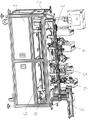
FIG. 1 is a schematic view of an overall first perspective structure of the present invention;
FIG. 2 is a front view of the present invention;
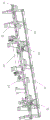
FIG. 3 is a schematic view of the feeding device of the present invention;
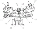
FIG. 4 is a schematic view of a dual-sided soldering device according to the present invention;
FIG. 5 is a schematic structural view of a connector lug riveting device according to the present invention;
FIG. 6 is a schematic diagram of a jacking power assembly according to the present invention;
FIG. 7 is a schematic view of the construction of the seam welding apparatus according to the present invention;
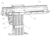
FIG. 8 is a schematic view of a material extracting apparatus according to the present invention;
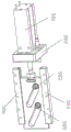
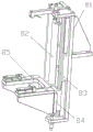
FIG. 9 is a schematic structural view of a second lifting device according to the present invention;
FIG. 10 is a schematic view of a reflow apparatus according to the present invention;
as shown in the figure: 1. a work table; 2. a first lifting device; 3. a feeding device; 4. a bilateral soldering device; 5. a connector lug riveting device; 6. a median seam welding device; 7. a material taking device; 8. a second lifting device; 9. a reflux transmission device; 31. a slide rail seven; 32. a feeding support; 33. a third push cylinder; 34. pushing a connecting plate; 35. positioning components II and 36 and a feeding track; 37. a first positioning component; 38. a material pushing block; 40. soldering a bottom plate; 41. a first jacking cylinder; 42. soldering a top plate; 43. a lifting plate; 44. an XYZ axis sliding table I; 45. an XYZ axis sliding table II; 46. a first welding gun; 47. a second welding gun; 48. a second hold-down cylinder; 49. pressing blocks; 50. riveting the bottom plate; 51. a second sliding plate; 52. riveting the vertical plate; 53. riveting the side plate II; 54. a first sliding plate; 55. a first down-pressure cylinder; 56. riveting and pressing blocks; 57. riveting the first side plate; 58. jacking a power assembly; 59. a support block; 581. a first push cylinder; 582. a cylinder fixing plate; 583. a first follower; 584. a third slide rail; 585. a second follower; 586. a fourth slide rail; 61. welding a support; 62. XYZ axis slipway III; 63. a third welding gun; 71. a material taking strut; 72. a fifth slide rail; 73. a first rodless cylinder; 74. a third sliding plate; 75. a sliding table cylinder; 76. a finger cylinder; 77. a material clamping block; 81. a second cylinder mounting plate; 82. a second rodless cylinder; 83. a sixth sliding rail; 84. a fourth sliding plate; 85. a U-shaped retainer plate; 91. a servo motor; 92. a first belt rotating shaft; 93. a first belt pulley; 94. a pulley bearing seat I; 95. a material supporting trolley; 96. a transfer rail; 97. a second belt pulley; 98. and a pulley bearing seat II.
Detailed Description
In order to facilitate an understanding of the invention, the invention is described in more detail below with reference to the accompanying drawings and specific examples. Preferred embodiments of the present invention are shown in the drawings. This invention may, however, be embodied in many different forms and should not be construed as limited to the embodiments set forth herein. Rather, these embodiments are provided so that this disclosure will be thorough and complete.
It will be understood that when an element is referred to as being "secured to" another element, it can be directly on the other element or intervening elements may also be present. When an element is referred to as being "connected" to another element, it can be directly connected to the other element or intervening elements may also be present. The use of the terms "fixed," "integrally formed," "left," "right," and the like in this specification is for illustrative purposes only, and elements having similar structures are designated by the same reference numerals in the figures.
Unless defined otherwise, all technical and scientific terms used herein have the same meaning as commonly understood by one of ordinary skill in the art to which this invention belongs. The terminology used in the description of the invention herein is for the purpose of describing particular embodiments only and is not intended to be limiting of the invention.
The present invention will be described in detail with reference to the accompanying drawings.
As shown in fig. 1 to 10, the welding device comprises a workbench 1, an iron shell feeding device is arranged on the left side of the workbench 1, the workbench 1 is divided into an upper layer and a lower layer, which are an upper platform and a lower platform respectively, a feeding device 3 is installed on the front side of the upper surface of the upper platform, a double-side soldering device 4, a connector lug riveting device 5, a middle seam welding device 6 and a material taking device 7 are sequentially arranged on the rear side of the feeding device 3 from left to right, the working ends of the double-side soldering device 4, the connector lug riveting device 5, the middle seam welding device 6 and the material taking device 7 are all located above a feeding rail 36 of the feeding device 3, a first positioning component 37 and a second positioning component 35 are respectively arranged at positions corresponding to the working ends of the feeding support 32 of the feeding device 3, the double-side soldering device 4 and the middle seam welding device 6, the first positioning component 37 and the second positioning component 35 are both located below the feeding rail 36, the upper surface of lower platform is provided with the backward flow conveyer 9 that is used for carrying the product to place the seat with the corresponding position department of material feeding unit 3, just left shape through-hole and right-hand shape through-hole have respectively been seted up with the discharge gate of backward flow conveyer 9 and the corresponding position department of feed inlet to the upper platform, be provided with elevating gear one 2 and elevating gear two 8 in left shape through-hole and the right-hand shape through-hole respectively, elevating gear one 2 holds in the palm the product from the discharge gate department of backward flow conveyer 9 and places the seat and deliver to material feeding unit's 3 feed inlet department with it, elevating gear two 8 holds in the palm the product from material feeding unit's 3 discharge gate department and places the seat and deliver to backward flow conveyer's 9 feed inlet department with it.
Further, the iron shell feeding device comprises a rack, an iron shell feeding track and a piece taking manipulator, wherein the rack is arranged on the left side of the workbench 1, the iron shell feeding track is fixed on the rack, the piece taking manipulator is fixed on the front side of the iron shell feeding track, and the piece taking manipulator takes materials from a discharge port of the iron shell feeding track and sends the materials to a product placing seat of the lifting device I2.
Furthermore, get a manipulator and be prior art, as long as can realize detecting the detection subassembly that welds effect and trail the welding seam and all be applicable to this technical scheme.
Preferably, the double-side soldering device 4 comprises a soldering tin bottom plate 40, a first jacking cylinder 41, a first guide rod, a second guide rod, a lifting plate 43, a soldering tin top plate 42, a first XYZ-axis sliding table 44, a second XYZ-axis sliding table 45, a first welding gun mounting plate, a second welding gun mounting plate, a first welding gun 46 and a second welding gun 47, wherein the soldering tin bottom plate 40 is fixed on the upper platform, the fixed end of the first jacking cylinder 41 is fixedly connected with the middle part of the upper surface of the soldering tin bottom plate 40, the working end of the first jacking cylinder 41 passes through the buffer mounting plate to be fixedly connected with the middle part of the lower surface of the lifting plate 43, the buffer mounting plate is fixedly connected with the first jacking cylinder 41, a hydraulic buffer is respectively fixed on the left side and the right side of the upper surface of the buffer mounting plate, the lower ends of the first guide rod and the second guide rod are respectively fixed on the left side and the right side of the first jacking cylinder 41, the upper, the welding device is characterized in that a first guide sleeve and a second guide sleeve are fixed at the contact positions of the lifting plate 43 and the first guide rod and the second guide rod respectively, the first guide sleeve and the second guide sleeve are connected with the first guide rod and the second guide rod in a sliding mode respectively, the first XYZ-axis sliding table 44 and the second XYZ-axis sliding table 45 are fixed on the left side and the right side of the upper surface of the lifting plate 43 respectively, the first welding gun mounting plate and the second welding gun mounting plate are fixedly connected with the movable ends of the first XYZ-axis sliding table 44 and the second XYZ-axis sliding table 45 respectively, the first welding gun 46 and the second welding gun 47 are fixed on the first welding gun mounting plate and the second welding.
Further, the material pressing assembly comprises a cylinder fixing support, a second downward pressing cylinder 48, a material pressing block 49 and a rubber block, the cylinder fixing support is fixed on the soldering tin top plate 42, the second downward pressing cylinder 48 is fixed on the front wall of the cylinder fixing support, the upper surface of the material pressing block 49 is fixedly connected with the working end of the second downward pressing cylinder 48, and the rubber block is fixed on the lower surface of the material pressing block 49.
Preferably, the connector lug riveting device 5 comprises a riveting bottom plate 50, a riveting vertical plate 52, a riveting side plate I57, a riveting side plate II 53, a riveting top plate, a slide rail I, a slide rail II, a first downward-pressing cylinder 55, a slide plate I54, a slide plate II 51, a riveting head, a supporting block 59 and a jacking power assembly 58, wherein the riveting bottom plate 50 is fixed on an upper platform, the riveting vertical plate 52 is vertically fixed in the middle of the upper surface of the riveting bottom plate 50, the lower ends of the riveting side plate I57 and the riveting side plate II 53 are respectively vertically fixed on the left side and the right side of the riveting vertical plate 52, the middle part of the right wall of the riveting side plate I57 and the middle part of the left wall of the riveting side plate II 53 are respectively fixedly connected with the left side and the right side of the riveting vertical plate 52, the upper ends of the riveting side plate I57, the riveting side plate II 53 and the riveting vertical plate 52 are respectively fixedly connected with the lower surface of the riveting top plate, the slide rail I and the slide rail II are, the first downward air cylinder 55 is fixed on the upper surface of the riveting top plate, the working end of the first downward air cylinder 55 passes through the riveting top plate and is clamped with the upper end of the first sliding plate 54, an upper slide block I and an upper slide block II are respectively fixed on the left side and the right side of the rear wall of the slide plate I54, the upper slide block I and the upper slide block II are respectively connected with a slide rail I and a slide rail II in a sliding way, a first lower sliding block and a second lower sliding block are respectively fixed on the left side and the right side of the rear wall of the second sliding plate 51, the first lower sliding block and the second lower sliding block are respectively connected with the first sliding rail and the second sliding rail in a sliding manner, the second sliding plate 51 is positioned below the first sliding plate 54, the riveting head is fixed in the middle of the front wall of the first sliding plate 54, the supporting block 59 is fixed on the front wall of the second sliding plate 51 corresponding to the riveting head, the jacking power assembly 58 is installed on the rear wall of the riveting vertical plate 52, and the working end of the jacking power assembly 58 is fixedly connected with the rear wall of the second sliding plate 51 through the riveting vertical plate 52.
Preferably, the jacking power assembly 58 comprises an air cylinder fixing plate 582, a first pushing air cylinder 581, a jacking slider, a third sliding rail 584, a fourth sliding rail 586, a first follower 583 and a second follower 585, the air cylinder fixing plate 582 is fixed on the lower side of the left wall of the first riveting side plate 57, the first pushing air cylinder 581 is fixed on the air cylinder fixing plate 582, the working end of the first pushing air cylinder 581 sequentially penetrates through the air cylinder fixing plate 582 and the first riveting side plate 57 to be clamped with the left end of the jacking slider, the positions of the rear wall of the riveting vertical plate 52 corresponding to the upper side and the lower side of the jacking slider are respectively fixed with the third sliding rail 584 and the fourth sliding rail 586, the upper side and the lower side of the jacking slider are respectively connected with the third sliding rail 584 and the fourth sliding rail 586 in a sliding manner, the front wall of the jacking slider is provided with two kidney-shaped holes, the rear ends of the first follower 583 and the second follower 585 are respectively embedded into the corresponding, the front ends of the first follower 583 and the second follower 585 are fixedly connected with the rear wall of the second sliding plate 51 through a follower connecting block.
Preferably, the center seam welding device 6 comprises a welding support 61, three XYZ shaft sliding tables 62, three welding gun mounting plates and three welding guns 63, wherein the welding support 61 is fixed on the upper platform, the three XYZ shaft sliding tables 62 are fixed on the welding support 61, the rear walls of the three welding gun mounting plates are fixedly connected with the movable ends of the three XYZ shaft sliding tables 62, and the three welding guns 63 are fixed on the front walls of the three mounting plates.
Preferably, the material taking device 7 comprises a material taking support 71, a material taking transverse plate, a first rodless cylinder 73, a slide rail five 72, a slide plate three 74, a sliding table cylinder 75, a cylinder mounting plate one, a finger cylinder 76 and a material clamping block 77, wherein the material taking support 71 is fixed on the upper platform, the rear wall of the material taking transverse plate is fixedly connected with the upper side of the front wall of the material taking support 71, the first rodless cylinder 73 is fixed on the upper side of the front wall of the material taking transverse plate through two cylinder fixing blocks, the slide rail five 72 is fixed on the lower side of the front wall of the material taking transverse plate, the upper side of the rear wall of the slide plate three 74 is fixedly connected with the movable end of the first rodless cylinder 73, the material taking slide block fixed on the lower side of the rear wall of the slide plate three 74 is slidably connected with the corresponding slide rail five 72, the sliding table cylinder 75 is fixed on, the finger cylinder 76 is fixed on the front wall of the cylinder mounting plate I, and a material clamping block 77 is fixed on the working end of the finger cylinder 76.
Preferably, the feeding device 3 comprises a feeding track 36, feeding supports 32 and a pushing assembly, wherein the feeding track 36 is horizontally fixed on the upper platform through a plurality of feeding supports 32, the pushing assembly is fixed on the feeding supports 32, and the working end of the pushing assembly is located below the feeding track 36.
Preferably, the second lifting device 8 includes a second cylinder mounting plate 81, a second cylinder fixing and connecting plate, a second rodless cylinder 82, a sixth sliding rail 83, a fourth sliding plate 84 and a U-shaped retainer plate 85, the second rodless cylinder 82 is fixed on the upper platform through the cylinder fixing and connecting plate, the second rodless cylinder 82 is fixed on the rear side of the left wall of the second cylinder mounting plate 81 through two cylinder fixing blocks, the sixth sliding rail 83 is fixed on the front side of the left wall of the second cylinder mounting plate 81, the rear side of the right wall of the fourth sliding plate 84 is fixedly connected with the movable end of the second rodless cylinder 82, a lifting slide block fixed on the front side of the right wall of the fourth sliding plate 84 is slidably connected with the sixth sliding rail 83, the U-shaped retainer plate 85 is fixed on the left wall of the fourth sliding plate 84 through two triangular plates, and a retainer block is respectively fixed on the front and rear sides of the upper surface of the U-shaped.
Preferably, the backflow conveying device 9 comprises a conveying rail 96, a belt conveying power assembly and a material supporting trolley 95, wherein the conveying rail 96 is fixed on a lower platform through a plurality of conveying supports, the belt conveying power assembly is fixedly installed on the lower platform, the movable end of the belt conveying power assembly is located between the conveying rails 96, the fixed end of the material supporting trolley 95 is fixedly connected with a belt of the belt conveying power assembly, and the movable end of the material supporting trolley 95 is in rolling connection with the conveying rails 96.
Furthermore, the first positioning assembly 37 comprises a cylinder connecting plate, a second jacking cylinder, a positioning support block, a first positioning slide rail and a second positioning slide rail, the left side of the rear wall of the cylinder connecting plate is fixedly connected with the feeding support 32, the second jacking cylinder is fixed on the lower side of the front wall of the cylinder connecting plate, the working end of the second jacking cylinder is clamped with the lower end of the positioning support block, the first positioning slide rail and the second positioning slide rail are respectively fixed at the positions, corresponding to the left side edge and the right side edge of the front wall of the cylinder connecting plate, of the positioning support block, and the left side edge and the right side edge of the positioning support block are respectively connected with the first positioning slide rail and the second positioning slide; the second positioning component 35 has the same structure as the first positioning component 37.
Further, the propelling movement material subassembly is including pushing away material slide, seven 31 of slide rail, ejector pad 38, third propelling movement cylinder 33 and pushing away material connecting plate 34, is fixed with one respectively on every pay-off support 32 and pushes away the material slide, seven 31 of slide rail and a plurality of material slide sliding connection that push away, the upper surface of seven 31 of slide rail evenly is fixed with a plurality of ejector pads 38 from a left side to the right side, third propelling movement cylinder 33 is fixed at the upper surface of upper mounting plate, the lower extreme that pushes away material connecting plate 34 and the work end joint of third propelling movement cylinder 33, the upper end and the seven 31 fixed connection of slide rail that push away material connecting plate 34.
Further, the difference between the first lifting device 2 and the second lifting device 8 is that: the upper end of cylinder fixed block is fixed with cylinder mounting panel three, be fixed with second propelling movement cylinder on the cylinder mounting panel three, just the working end of second propelling movement cylinder sets up towards the right side, the working end of second propelling movement cylinder is fixed with and pushes away the material gluey post.
Further, the belt transmission power assembly comprises a motor fixing plate, a first belt pulley bearing seat 94, a second belt pulley bearing seat 98, a first belt pulley 93, a first belt rotating shaft 92, a servo motor 91, a second belt pulley 97 and a second belt rotating shaft, wherein the motor fixing plate, the first belt pulley bearing seat 94 and the second belt pulley bearing seat 98 are all fixed on the lower platform, the first belt pulley bearing seat 94 and the second belt pulley bearing seat 98 are respectively positioned at the left side and the right side of the transmission rail 96, the motor fixing plate is positioned at the rear side of the first belt pulley bearing seat 94, the first belt pulley 93 is installed on the first belt pulley bearing seat 94 through the first belt rotating shaft 92, the servo motor 91 is fixed on the rear wall of the motor fixing plate, the working end of the servo motor fixing plate penetrates through the motor fixing plate to be connected with the rear end of the first belt rotating shaft 92 through a coupler, the second belt pulley, the first belt pulley 93 and the second belt pulley 97 are in transmission connection through a belt.
The working principle is as follows: when the equipment starts to work, firstly, a workpiece to be processed is taken out by the workpiece taking manipulator from a discharge port of the iron shell feeding track and is sent to a product placing seat of the lifting device I2, the second pushing cylinder pushes the product placing seat to move rightwards and sends the product placing seat to a feed port of the feeding device 3, the third pushing cylinder 33 pushes the sliding rail seven 31 and the pushing block 38 to move rightwards, the pushing block 38 pushes the product placing seat to the position of the double-side soldering device 4, the positioning assembly II 35 starts to work, the second jacking cylinder pushes the positioning support block to move upwards to clamp the product placing seat, then the double-side soldering device 4 starts to work, the first jacking cylinder 41 pulls the lifting plate 43 and the first welding gun 46 as well as the second welding gun 47 to move downwards, so that the working ends of the first welding gun 46 and the second welding gun 47 respectively move to the left side and the right side of the workpiece to be processed, and the second pressing cylinder 48 pushes the block 49 to, fixing a workpiece to be processed on a product placing seat, welding the joint of the upper protective shell and the lower protective shell by a first welding gun 46 and a second welding gun 47, and resetting the first positioning assembly 37 and the double-side tin soldering device 4;
then, the pushing and feeding assembly sends the product placing seat to the position of the connector lug riveting device 5, the second positioning assembly 35 clamps the product positioning seat according to the working procedure of the first positioning assembly 37, the connector lug riveting device 5 starts to work, the first pushing cylinder 581 pushes the jacking sliding block to slide rightwards, the first follower 583 and the second follower 585 drive the second sliding plate 51 to move upwards until the supporting block 59 contacts the USB connecting wire, then the first pushing cylinder 55 pushes the first sliding plate 54 and the riveting head to move downwards, the connecting position of the upper protective shell and the lower protective shell is riveted and fixed, and after the riveting is completed, the connector lug riveting device 5 resets; then the pushing component conveys the product placing seat to the position of the middle seam welding device 6, and the third welding gun 63 welds the riveting seam;
then the second lifting device 8 starts to work, the second rodless cylinder 82 drives the fourth sliding plate 84 to move upwards, the U-shaped retainer plate 85 and the feeding rail 36 are located on the same horizontal plane, then the feeding component is pushed to send the product placing seat onto the U-shaped retainer plate 85, the material taking device 7 starts to work, the first rodless cylinder 73 drives the third sliding plate 74 to move leftwards to the position above the processed product, the sliding table cylinder 75 drives the finger cylinder 76 to move downwards, and the product is clamped and sent out of the workbench 1; then the second rodless cylinder 82 drives the product placing seat to descend downwards, so that the product placing seat is placed on the material supporting trolley 95, the servo motor 91 rotates to drive the belt rotating shaft I92 and the belt pulley I93 to rotate synchronously, and the belt drives the material supporting trolley 95 to convey the product placing seat to a discharge port of the conveying rail 96;
finally, the first lifting device 2 starts to work, and the product placing seat is conveyed to a feeding opening of the feeding rail 36 according to the working procedure of the second lifting device 8; and finishing the work of the equipment.
Has the advantages that: according to the invention, the bilateral tin soldering device is arranged to weld the joint of the upper protective shell and the lower protective shell, so that the phenomena of looseness and separation of the upper protective shell and the lower protective shell are effectively avoided, the tin soldering angle is accurate, and the tin soldering speed is high; by arranging the connector lug riveting device, the connecting wire is riveted and fixed with the upper protective shell and the lower protective shell, so that the connecting wire is prevented from being separated from the terminal due to stress, the riveting is accurate and quick, and the working efficiency is improved; the center seam welding device is arranged, so that the riveted part is prevented from cracking, and the connection of the riveted part is firmer; the automatic welding machine is high in automation degree and convenient to operate, does not need manual operation, reduces welding errors, reduces production cost, improves working efficiency, and has good market application value.
The technical features mentioned above are combined with each other to form various embodiments which are not listed above, and all of them are regarded as the scope of the present invention described in the specification; also, modifications and variations may be suggested to those skilled in the art in light of the above teachings, and it is intended to cover all such modifications and variations as fall within the true spirit and scope of the invention as defined by the appended claims.
Claims (9)
1. The utility model provides an auto-parts weld forming equipment, includes the workstation, sets up iron-clad loading attachment in the left side of workstation, the workstation is two-layer about divideing into, is upper mounting plate and lower platform, its characterized in that respectively: the front side of the upper surface of the upper platform is provided with a feeding device, the rear side of the feeding device is sequentially provided with a double-side soldering tin device, a connector lug riveting device, a middle seam welding device and a material taking device from left to right, the working ends of the double-side soldering tin device, the connector lug riveting device, the middle seam welding device and the material taking device are all positioned above a feeding track of the feeding device, a first positioning assembly and a second positioning assembly are respectively arranged at the corresponding positions of a feeding support of the feeding device and the working ends of the double-side soldering tin device and the middle seam welding device, the first positioning assembly and the second positioning assembly are both positioned below the feeding track, a backflow conveying device used for conveying a product placing seat is arranged at the corresponding position of the upper surface of the lower platform and the feeding device, and a left-shaped through hole and a right-shaped through hole are respectively arranged at the corresponding positions of a discharge port and a feed port of the, the device comprises a left side-shaped through hole, a right side-shaped through hole, a first lifting device and a second lifting device, wherein the first lifting device and the second lifting device are arranged in the left side-shaped through hole and the right side-shaped through hole respectively, the first lifting device lifts a product placing seat from a discharge port of the backflow conveying device and conveys the product placing seat to a feed port of the feeding device, and the second lifting device lifts the product placing seat from the discharge port of the feeding device and conveys the product to the feed port of the backflow conveying device.
2. The automobile accessory welding and forming device according to claim 1, wherein: the double-side tin soldering device comprises a tin soldering bottom plate, a first jacking cylinder, a first guide rod, a second guide rod, a lifting plate, a tin soldering top plate, a first XYZ-axis sliding table, a second XYZ-axis sliding table, a first welding gun mounting plate, a second welding gun mounting plate, a first welding gun and a second welding gun, wherein the tin soldering bottom plate is fixed on an upper platform, the fixed end of the first jacking cylinder is fixedly connected with the middle part of the upper surface of the tin soldering bottom plate, the working end of the first jacking cylinder penetrates through a buffer mounting plate to be fixedly connected with the middle part of the lower surface of the lifting plate, the buffer mounting plate is fixedly connected with the first jacking cylinder, a hydraulic buffer is respectively fixed on the left side and the right side of the upper surface of the buffer mounting plate, the lower ends of the first guide rod and the second guide rod are respectively fixed on the left side and the right side of the first, the welding device comprises a lifting plate, a guide rod I, a guide sleeve II, a welding gun mounting plate I, a welding gun mounting plate II, a material pressing assembly and a material pressing assembly, wherein the lifting plate is fixedly provided with the guide sleeve I and the guide rod II at contact positions respectively, the guide sleeve I and the guide sleeve II are slidably connected with the guide rod I and the guide rod II respectively, the XYZ-axis sliding table I and the XYZ-axis sliding table II are fixedly arranged on the left side and the right side of the upper surface of the lifting plate respectively, the welding gun mounting plate I and the welding gun mounting plate II are fixedly connected with the movable ends of the XYZ-axis sliding table I and the XYZ-axis sliding table.
3. The automobile accessory welding and forming device according to claim 1, wherein: the connector lug riveting device comprises a riveting bottom plate, a riveting vertical plate, a riveting side plate I, a riveting side plate II, a riveting top plate, a slide rail I, a slide rail II, a first lower pressing air cylinder, a slide plate I, a slide plate II, a riveting head, a supporting block and a jacking power assembly, wherein the riveting bottom plate is fixed on an upper platform, the riveting vertical plate is vertically fixed at the middle part of the upper surface of the riveting bottom plate, the lower ends of the riveting side plate I and the riveting side plate II are respectively vertically fixed at the left side and the right side of the riveting vertical plate, the middle part of the right wall of the riveting side plate I and the middle part of the left wall of the riveting side plate II are respectively and fixedly connected with the left side and the right side of the riveting vertical plate, the upper ends of the riveting side plate I, the riveting side plate II and the riveting vertical plate are respectively and fixedly connected with the lower surface of the riveting top plate, the slide rail I and the slide rail II are respectively and vertically fixed at the left side, the working end of the first downward pressing air cylinder penetrates through the riveting top plate to be clamped with the upper end of the first sliding plate, the left side and the right side of the rear wall of the first sliding plate are respectively fixed with a first upper sliding block and a second upper sliding block, the first upper sliding block and the second upper sliding block are respectively in sliding connection with the first sliding rail and the second sliding rail, the left side and the right side of the rear wall of the second sliding plate are respectively fixed with a first lower sliding block and a second lower sliding block, the first lower sliding block and the second lower sliding block are respectively in sliding connection with the first sliding rail and the second sliding rail, the second sliding plate is located below the first sliding plate, the riveting head is fixed in the middle of the front wall of the first sliding plate, the supporting block is fixed at the position, corresponding to the riveting head, of the front wall of the second sliding plate, the jacking power assembly is installed on the rear wall of the.
4. The automobile accessory welding and forming device according to claim 3, wherein: the jacking power assembly comprises a cylinder fixing plate, a first pushing cylinder, a jacking sliding block, a third sliding rail, a fourth sliding rail, a first follower and a second follower, the cylinder fixing plate is fixed on the lower side of the left wall of the first riveting side plate, the first pushing cylinder is fixed on the cylinder fixing plate, and the working end of the first pushing cylinder sequentially passes through the cylinder fixing plate and the first riveting side plate to be clamped with the left end of the jacking sliding block, a third sliding rail and a fourth sliding rail are respectively fixed on the rear wall of the riveting vertical plate and the corresponding positions of the upper side edge and the lower side edge of the jacking sliding block, the upper side edge and the lower side edge of the jacking sliding block are respectively connected with the third sliding rail and the fourth sliding rail in a sliding way, the front wall of the jacking sliding block is provided with two kidney-shaped holes, the rear ends of the first follower and the second follower are respectively embedded into the corresponding waist-shaped holes, and the front ends of the first follower and the second follower are fixedly connected with the rear wall of the second sliding plate through the follower connecting blocks.
5. The automobile accessory welding and forming device according to claim 1, wherein: the center seam welding device comprises a welding support, an XYZ-axis sliding table III, a welding gun mounting plate III and a welding gun III, wherein the welding support is fixed on the upper platform, the XYZ-axis sliding table III is fixed on the welding support, the rear wall of the welding gun mounting plate III is fixedly connected with the movable end of the XYZ-axis sliding table III, and the welding gun III is fixed on the front wall of the mounting plate III.
6. The automobile accessory welding and forming device according to claim 1, wherein: the material taking device comprises a material taking support column, a material taking transverse plate, a first rodless cylinder, a fifth sliding rail, a third sliding plate, a sliding table cylinder, a first cylinder mounting plate, a finger cylinder and a material clamping block, wherein the material taking support column is fixed on an upper platform, the rear wall of the material taking transverse plate is fixedly connected with the upper side of the front wall of the material taking support column, the first rodless cylinder is fixed on the upper side of the front wall of the material taking transverse plate through two cylinder fixing blocks, the fifth sliding rail is fixed on the lower side of the front wall of the material taking transverse plate, the upper side of the rear wall of the third sliding plate is fixedly connected with the movable end of the first rodless cylinder, a material taking sliding block fixed on the lower side of the rear wall of the third sliding plate is in sliding connection with the fifth corresponding sliding rail, the sliding table cylinder is fixed on the front, and a material clamping block is fixed at the working end of the finger cylinder.
7. The automobile accessory welding and forming device according to claim 1, wherein: the feeding device comprises a feeding track, a feeding support and a pushing assembly, the feeding track is horizontally fixed on the upper platform through a plurality of feeding supports, the pushing assembly is fixed on the feeding support, and the working end of the pushing assembly is located below the feeding track.
8. The automobile accessory welding and forming device according to claim 1, wherein: the lifting device II comprises a cylinder mounting plate II, a cylinder fixed connecting plate, a second rodless cylinder, a sliding rail six, a sliding plate four and a U-shaped supporting plate, the second rodless cylinder is fixed on the upper platform through the cylinder fixed connecting plate, the second rodless cylinder is fixed on the rear side of the left wall of the cylinder mounting plate II through two cylinder fixed blocks, the sliding rail six is fixed on the front side of the left wall of the cylinder mounting plate two, the rear side of the right wall of the sliding plate four is fixedly connected with the movable end of the second rodless cylinder, a lifting sliding block fixed on the front side of the right wall of the sliding plate four is connected with the sliding rail six in a sliding mode, the U-shaped supporting plate is fixed on the left wall of the sliding plate four through two triangular plates, and supporting cushion blocks are fixed on the front and rear sides of the upper surface of the U-.
9. The automobile accessory welding and forming device according to claim 1, wherein: the backflow conveying device comprises a conveying track, a belt conveying power assembly and a material supporting trolley, wherein the conveying track is fixed on a lower platform through a plurality of conveying supports, the belt conveying power assembly is fixedly installed on the lower platform, the movable end of the belt conveying power assembly is located between the conveying tracks, the fixed end of the material supporting trolley is fixedly connected with a belt of the belt conveying power assembly, and the movable end of the material supporting trolley is in rolling connection with the conveying tracks.
Priority Applications (1)
| Application Number | Priority Date | Filing Date | Title |
|---|---|---|---|
| CN202010276776.1A CN111266689A (en) | 2020-04-10 | 2020-04-10 | Auto-parts welding forming equipment |
Applications Claiming Priority (1)
| Application Number | Priority Date | Filing Date | Title |
|---|---|---|---|
| CN202010276776.1A CN111266689A (en) | 2020-04-10 | 2020-04-10 | Auto-parts welding forming equipment |
Publications (1)
| Publication Number | Publication Date |
|---|---|
| CN111266689A true CN111266689A (en) | 2020-06-12 |
Family
ID=70992710
Family Applications (1)
| Application Number | Title | Priority Date | Filing Date |
|---|---|---|---|
| CN202010276776.1A Withdrawn CN111266689A (en) | 2020-04-10 | 2020-04-10 | Auto-parts welding forming equipment |
Country Status (1)
| Country | Link |
|---|---|
| CN (1) | CN111266689A (en) |
Cited By (2)
| Publication number | Priority date | Publication date | Assignee | Title |
|---|---|---|---|---|
| CN112886355A (en) * | 2021-01-11 | 2021-06-01 | 浙江盛越电子科技有限公司 | Full-automatic soldering tin assembly production line |
| CN114178866A (en) * | 2022-01-10 | 2022-03-15 | 苏州帕缇科勒智能科技有限公司 | Automatic wire rod aftertreatment production facility |
Citations (5)
| Publication number | Priority date | Publication date | Assignee | Title |
|---|---|---|---|---|
| CN103252551A (en) * | 2012-11-29 | 2013-08-21 | 辜国彪 | Automatic wire welding process and automatic wire welding machine |
| CN206250541U (en) * | 2016-11-08 | 2017-06-13 | 惠州市和宏电线电缆有限公司 | A kind of full-automatic processing production line of data wire |
| CN206543936U (en) * | 2016-12-31 | 2017-10-10 | 东莞市和众智能设备有限公司 | A kind of riveting tin soldering machine |
| CN107756050A (en) * | 2017-11-23 | 2018-03-06 | 宁波禹泰自动化科技有限公司 | Photovoltaic rat tail automatic assembling machine |
| CN209919418U (en) * | 2019-05-24 | 2020-01-10 | 颜佩卿 | Automatic feeding and discharging manipulator workpiece taking device |
-
2020
- 2020-04-10 CN CN202010276776.1A patent/CN111266689A/en not_active Withdrawn
Patent Citations (5)
| Publication number | Priority date | Publication date | Assignee | Title |
|---|---|---|---|---|
| CN103252551A (en) * | 2012-11-29 | 2013-08-21 | 辜国彪 | Automatic wire welding process and automatic wire welding machine |
| CN206250541U (en) * | 2016-11-08 | 2017-06-13 | 惠州市和宏电线电缆有限公司 | A kind of full-automatic processing production line of data wire |
| CN206543936U (en) * | 2016-12-31 | 2017-10-10 | 东莞市和众智能设备有限公司 | A kind of riveting tin soldering machine |
| CN107756050A (en) * | 2017-11-23 | 2018-03-06 | 宁波禹泰自动化科技有限公司 | Photovoltaic rat tail automatic assembling machine |
| CN209919418U (en) * | 2019-05-24 | 2020-01-10 | 颜佩卿 | Automatic feeding and discharging manipulator workpiece taking device |
Non-Patent Citations (1)
| Title |
|---|
| 设计是门艺术: "typec-USB铁壳卯压两侧焊锡自动机", 《沐风图纸》 * |
Cited By (2)
| Publication number | Priority date | Publication date | Assignee | Title |
|---|---|---|---|---|
| CN112886355A (en) * | 2021-01-11 | 2021-06-01 | 浙江盛越电子科技有限公司 | Full-automatic soldering tin assembly production line |
| CN114178866A (en) * | 2022-01-10 | 2022-03-15 | 苏州帕缇科勒智能科技有限公司 | Automatic wire rod aftertreatment production facility |
Similar Documents
| Publication | Publication Date | Title |
|---|---|---|
| CN109018951B (en) | Tray conveying and switching system on automatic production line | |
| CN108098196B (en) | Automatic production line for assembling and welding of breaker robot | |
| CN105895834B (en) | A kind of automatically processing device of battery cover board | |
| CN107959039A (en) | A kind of battery core assembles integrated automation production line | |
| CN111266689A (en) | Auto-parts welding forming equipment | |
| CN109287112B (en) | Automatic PCBA assembling equipment | |
| CN205723664U (en) | A kind of automatically processing device of battery cover board | |
| CN207303250U (en) | A kind of battery core assembles integrated automation production line | |
| CN111203665B (en) | Welding equipment | |
| CN109719518B (en) | General equipment of modularization hanging beam formula longmen structure | |
| CN212049485U (en) | Feeding and discharging conveying device for screen printing machine and automatic screen printing machine | |
| CN211843572U (en) | Two-sided pad pasting equipment | |
| CN209736810U (en) | Connect full-automatic tin device that adds | |
| CN112372302A (en) | Collude indisputable equipment of welding and milling flat welding seam device | |
| CN112719900A (en) | Automatic riveting and pressing welding equipment for bus plates and operation method of automatic riveting and pressing welding equipment | |
| CN108840103B (en) | Automatic feeding and transferring device for glass panels | |
| CN217371527U (en) | Vertical straight-line numerical control tool changing machining center | |
| CN110587417A (en) | Feeding and discharging device for silicon rod surface grinding and chamfering grinding machine and detection method | |
| CN213034792U (en) | Numerical control drilling device with automatic feeding and discharging structure | |
| CN111136159A (en) | Numerical control production line for punching automobile longitudinal beam flat plate | |
| CN211916065U (en) | A subassembly machine for elevator accessory | |
| CN219426272U (en) | Double-station feeding and discharging device for round bar and cuboid workpieces | |
| CN218638782U (en) | Laminate angle welding device | |
| CN217296025U (en) | Nut plate positioning and conveying mechanism | |
| CN219362289U (en) | Intermittent conveying device |
Legal Events
| Date | Code | Title | Description |
|---|---|---|---|
| PB01 | Publication | ||
| PB01 | Publication | ||
| SE01 | Entry into force of request for substantive examination | ||
| SE01 | Entry into force of request for substantive examination | ||
| WW01 | Invention patent application withdrawn after publication |
Application publication date: 20200612 |
|
| WW01 | Invention patent application withdrawn after publication |