CN111251154A - Mechanical cutting deruster - Google Patents
Mechanical cutting deruster Download PDFInfo
- Publication number
- CN111251154A CN111251154A CN202010296821.XA CN202010296821A CN111251154A CN 111251154 A CN111251154 A CN 111251154A CN 202010296821 A CN202010296821 A CN 202010296821A CN 111251154 A CN111251154 A CN 111251154A
- Authority
- CN
- China
- Prior art keywords
- wheel
- driving
- derusting
- wheels
- rust
- Prior art date
- Legal status (The legal status is an assumption and is not a legal conclusion. Google has not performed a legal analysis and makes no representation as to the accuracy of the status listed.)
- Pending
Links
Images


Classifications
-
- B—PERFORMING OPERATIONS; TRANSPORTING
- B24—GRINDING; POLISHING
- B24B—MACHINES, DEVICES, OR PROCESSES FOR GRINDING OR POLISHING; DRESSING OR CONDITIONING OF ABRADING SURFACES; FEEDING OF GRINDING, POLISHING, OR LAPPING AGENTS
- B24B27/00—Other grinding machines or devices
- B24B27/033—Other grinding machines or devices for grinding a surface for cleaning purposes, e.g. for descaling or for grinding off flaws in the surface
-
- B—PERFORMING OPERATIONS; TRANSPORTING
- B08—CLEANING
- B08B—CLEANING IN GENERAL; PREVENTION OF FOULING IN GENERAL
- B08B15/00—Preventing escape of dirt or fumes from the area where they are produced; Collecting or removing dirt or fumes from that area
- B08B15/04—Preventing escape of dirt or fumes from the area where they are produced; Collecting or removing dirt or fumes from that area from a small area, e.g. a tool
-
- B—PERFORMING OPERATIONS; TRANSPORTING
- B23—MACHINE TOOLS; METAL-WORKING NOT OTHERWISE PROVIDED FOR
- B23D—PLANING; SLOTTING; SHEARING; BROACHING; SAWING; FILING; SCRAPING; LIKE OPERATIONS FOR WORKING METAL BY REMOVING MATERIAL, NOT OTHERWISE PROVIDED FOR
- B23D79/00—Methods, machines, or devices not covered elsewhere, for working metal by removal of material
-
- B—PERFORMING OPERATIONS; TRANSPORTING
- B24—GRINDING; POLISHING
- B24B—MACHINES, DEVICES, OR PROCESSES FOR GRINDING OR POLISHING; DRESSING OR CONDITIONING OF ABRADING SURFACES; FEEDING OF GRINDING, POLISHING, OR LAPPING AGENTS
- B24B27/00—Other grinding machines or devices
- B24B27/0076—Other grinding machines or devices grinding machines comprising two or more grinding tools
-
- B—PERFORMING OPERATIONS; TRANSPORTING
- B24—GRINDING; POLISHING
- B24B—MACHINES, DEVICES, OR PROCESSES FOR GRINDING OR POLISHING; DRESSING OR CONDITIONING OF ABRADING SURFACES; FEEDING OF GRINDING, POLISHING, OR LAPPING AGENTS
- B24B41/00—Component parts such as frames, beds, carriages, headstocks
- B24B41/005—Feeding or manipulating devices specially adapted to grinding machines
-
- B—PERFORMING OPERATIONS; TRANSPORTING
- B24—GRINDING; POLISHING
- B24B—MACHINES, DEVICES, OR PROCESSES FOR GRINDING OR POLISHING; DRESSING OR CONDITIONING OF ABRADING SURFACES; FEEDING OF GRINDING, POLISHING, OR LAPPING AGENTS
- B24B55/00—Safety devices for grinding or polishing machines; Accessories fitted to grinding or polishing machines for keeping tools or parts of the machine in good working condition
- B24B55/06—Dust extraction equipment on grinding or polishing machines
Abstract
The invention discloses a mechanical cutting derusting machine, which comprises at least two derusting wheels, wherein one derusting wheel is transversely arranged, the other derusting wheel is longitudinally arranged, the derusting wheels comprise a plurality of steel wire wheels and rotating wheels, the rotating wheels are positioned between the steel wire wheels, and hard alloy tool bits are arranged on the rotating wheels; the rust removing wheel is provided with a driving mechanism, the driving mechanism is positioned in an external mechanism, and the external mechanism comprises a handheld mechanism, a driven table type mechanism and a driving table type mechanism; the dust removing device is characterized in that a dust removing cover is further arranged above the rust removing wheel, a plurality of suction nozzles penetrate through the dust removing cover, and the suction nozzles are communicated with a dust collector through a pipeline. The invention reduces the labor intensity of workers, saves the cost, ensures the product quality, leads the steel wire wheel to be contacted with the steel plate in the process of high-speed rotation of the derusting wheel to achieve the purpose of derusting, and simultaneously drives the carbide tool bit to longitudinally and transversely scratch the steel plate through the rotating wheel to increase the roughness of the surface of the steel plate, thus leading the surface structure of the steel plate to reach the roughness of Sa2.5-3.0 grade.
Description
Technical Field
The invention relates to the technical field of rust removing equipment, in particular to a mechanical cutting rust remover.
Background
The steel plate is a flat steel plate which is cast by molten steel, cooled and pressed, is flat and rectangular, and can be directly rolled or cut by a wide steel belt. When the steel plate is placed in an outdoor open environment, the surface is very easy to oxidize, so that the surface is rusted, the appearance quality is influenced, a plurality of subsequent works such as painting, welding and the like are difficult to carry out, and if the steel plate is rusted seriously, the steel plate cannot be used, so that a large amount of economic loss is caused. The rust removal work is a common traditional rust removal method in the steel industry, an operator uses tools such as iron gauze to manually polish, the manual rust removal time is long, the rust removal effect is not ideal, time and labor are wasted, the expected effect cannot be achieved, and generally only rust can be removed, and the technical standard of Sa2.5 grade-3.0 grade is difficult to achieve.
Disclosure of Invention
The invention aims to provide a mechanical cutting deruster aiming at the defects and shortcomings of the prior art.
In order to achieve the purpose, the invention adopts the technical scheme that: the utility model provides a machine cutting deruster which innovation point lies in: the rust removing device comprises at least two rust removing wheels, wherein one rust removing wheel is transversely arranged, the other rust removing wheel is longitudinally arranged, the rust removing wheels comprise a plurality of steel wire wheels and a rotating wheel, the rotating wheel is positioned between the steel wire wheels, and a hard alloy cutter head is arranged on the rotating wheel; the rust removing wheel is provided with a driving mechanism, the driving mechanism is positioned in an external mechanism, and the external mechanism comprises a handheld mechanism, a passive table type mechanism and an active table type mechanism; the dust removing device is characterized in that a dust removing cover is further arranged above the rust removing wheel, a plurality of suction nozzles penetrate through the dust removing cover, and the suction nozzles are communicated with a dust collector through a pipeline.
Further, actuating mechanism includes driving motor, set up action wheel, bearing frame and bevel gear group on driving motor's the output shaft respectively, set up the pivot on the rust cleaning wheel respectively, and one of them pivot is passed through bevel gear group and is connected with driving motor meshing transmission, and another pivot sets up the action wheel, the action wheel is connected with following driving wheel transmission through setting up the belt, and is connected with external mechanism fixed connection through setting up the bearing frame in this pivot.
Further, handheld mechanism includes the casing, set up control circuit board, battery in the casing, its outside sets up interface, shift knob and handheld portion that charges, the dust catcher is located terminal surface under the casing, and the pipeline runs through casing and dust catcher intercommunication.
Furthermore, the passive table type mechanism comprises a conveying frame, at least two groups of derusting wheels and driving mechanisms are arranged on the conveying frame, and the conveying frame is positioned below the derusting wheels; the conveying frame is driven by a motor, a plurality of conveying rollers are arranged in the conveying frame, one end of each conveying roller penetrates through the frame body and is provided with a transmission chain wheel, the transmission chain wheels are connected through transmission chain transmission, a driven rotating wheel is further arranged on one conveying roller, a driving rotating wheel is arranged on an output shaft of the motor, and the driving rotating wheel is in transmission connection with the driven rotating wheel; the dust collector is positioned on the side of the conveying frame disc.
Furthermore, the driving table type mechanism comprises a workbench, a linear guide rail and a slide rail assembly are respectively arranged on the left side and the right side of the workbench, an installation seat is arranged on the linear guide rail, a driving mechanism is arranged on the installation seat, a bearing support is arranged at one end, away from the driving mechanism, of an upper rotating shaft of the derusting wheel, the bearing support is fixedly connected with the slide rail assembly, and the driving mechanism drives the derusting wheel to move through the linear guide rail; the dust collector is positioned on the side of the workbench disc.
Furthermore, the knife face of the hard alloy knife head is in a sawtooth shape, and the sawtooth has elasticity.
Furthermore, the top of the steel wire wheel is in a bent shape.
Further, the suction nozzles are distributed at equal intervals and are arranged in a downward inclined mode.
Further, the dust collector comprises a detachable dust collecting barrel.
After adopting the structure, the invention has the beneficial effects that:
the steel wire wheel rust removing device is simple in structure, convenient and practical, improves working efficiency, reduces labor intensity of workers, saves cost, ensures product quality, enables the steel wire wheel to be in contact with a steel plate in the high-speed rotation process of the rust removing wheel to achieve the purpose of rust removing, drives the hard alloy tool bit to longitudinally and transversely scratch the steel plate through the rotating runner, increases the roughness of the surface of the steel plate, and enables the surface structure of the steel plate to reach Sa2.5-3.0-level roughness.
Drawings
FIG. 1 is a schematic top view of a derusting wheel in the invention;
FIG. 2 is a schematic side view of a wire wheel in the rust removing wheel according to the present invention;
FIG. 3 is a side view schematic diagram of a transfer wheel in the rust removing wheel of the present invention;
FIG. 4 is a schematic structural view of a derusting wheel and a driving mechanism in the invention;
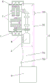
FIG. 5 is a schematic top view of the structure of embodiment 1;
FIG. 6 is a schematic top view of the structure of embodiment 2;
fig. 7 is a schematic top view of the structure of embodiment 3.
Description of reference numerals:
the dust removing device comprises a rust removing wheel 1, a steel wire wheel 11, a rotating wheel 12, a hard alloy tool bit 13, a driving mechanism 2, a driving motor 21, a driving wheel 22, a bearing seat 23, a bevel gear set 24, a rotating shaft 25, a driven wheel 26, a handheld mechanism 3, a shell 31, a charging interface 32, a switch button 33, a handheld part 34, a driven table mechanism 4, a conveying frame 41, a motor 42, a conveying roller 43, a transmission chain wheel 44, a transmission chain 45, a driven rotating wheel 46, a driving rotating wheel 47, a driving table mechanism 5, a working table 51, a linear guide rail 52, a sliding rail component 53, a mounting seat 54, a bearing support 55, a dust hood 6, a suction nozzle 7, a pipeline 8 and a dust collector.
Detailed Description
The invention will be further described with reference to the accompanying drawings.
In order to make the objects, technical solutions and advantages of the present invention more apparent, the present invention will be described in detail with reference to the accompanying drawings and the detailed description. It should be understood that the detailed description and specific examples, while indicating the invention, are intended for purposes of illustration only and are not intended to limit the scope of the invention.
Example 1
Referring to fig. 1-5, a mechanical cutting rust remover comprises at least two rust removing wheels 1, wherein one rust removing wheel is transversely arranged, the other rust removing wheel is longitudinally arranged, the rust removing wheel 1 comprises a plurality of steel wire wheels 11 and a rotating wheel 12, the rotating wheel 12 is positioned between the steel wire wheels 11, and a hard alloy cutter head 13 is arranged on the rotating wheel 12; the rust removing wheel 1 is provided with a driving mechanism 2, and the driving mechanism 2 is positioned in the handheld mechanism 3; a dust hood 6 is further arranged above the derusting wheel 1, a plurality of suction nozzles 7 penetrate through the dust hood 6, and the suction nozzles 7 are communicated with a dust collector 9 through a pipeline 8. Specifically, when the derusting wheel 1 rotates, the steel wire wheel 11 is in contact with a steel plate to achieve the purpose of derusting, and meanwhile, the rotating wheel 12 drives the hard alloy tool bit 13 to longitudinally and transversely scratch the steel plate, so that the roughness of the surface of the steel plate is increased, and the surface structure of the steel plate can reach Sa2.5-3.0 level roughness; the handheld driving mechanism 3 is small in size, convenient to carry, suitable for outgoing operation, capable of improving working efficiency, reducing labor intensity of workers, saving cost and ensuring product quality; dust of rust cleaning in-process can be through dust excluding hood 6 and suction nozzle 7, and the rethread pipeline 8 is by the suction cleaner 9 in, avoids the iron rust to be blown away by wind, guarantees that operating personnel's breathing is healthy, and the iron fillings that produce can be retrieved moreover and are treated the utilization, practices thrift the cost, saves the resource.
In this embodiment, the driving mechanism 2 includes a driving motor 21, a driving wheel 22, a bearing seat 23 and a bevel gear set 24 are respectively disposed on an output shaft of the driving motor 21, rotating shafts 25 are respectively disposed on the derusting wheel 1, one of the rotating shafts is in meshing transmission connection with the driving motor 21 through the bevel gear set 24, the other rotating shaft is disposed with a driven wheel 26, the driven wheel 26 is in transmission connection with the driving wheel 22 through a belt, and the rotating shaft is fixedly connected with an external mechanism through the bearing seat 23. Specifically, after the driving motor 21 is started, the driving wheel 22 and the bevel gear set 24 are driven to rotate, and the rotating shaft 25 is driven to rotate, so that the rotation of the derusting wheel 1 is realized, and the purpose of derusting a steel plate is achieved.
In this embodiment, the handheld mechanism 3 includes a housing 31, a control circuit board and a battery are disposed in the housing 31, a charging interface 32, a switch button 33 and a handheld portion 34 are disposed outside the housing 31, the dust collector 9 is located on the lower end surface of the housing 31, and the duct 8 penetrates through the housing 31 and is communicated with the dust collector 9. Specifically, the volume of the handheld driving mechanism 3 is similar to that of a handheld cutting machine, and the handheld driving mechanism is convenient to carry.
In this embodiment, the knife face of carbide tool bit 13 is the cockscomb structure, and the sawtooth has elasticity, is convenient for carry out the fish tail to the steel sheet surface, improves work efficiency.
In this embodiment, the top of the steel wire wheel 11 is bent, and when rotating, the steel wire is equivalent to being shoveled on a steel plate, and rust removal is performed.
In this embodiment, suction nozzle 7 equidistance distributes, and the downward sloping sets up, utilizes iron fillings and the iron rust absorption that will raise.
In this embodiment, the vacuum cleaner 9 includes a detachable dust collecting tube, which facilitates cleaning and recycling at a later stage.
Example 2
Referring to fig. 1-4 and 6, the mechanical cutting rust remover comprises at least two rust removing wheels 1, wherein one rust removing wheel is transversely arranged, the other rust removing wheel is longitudinally arranged, the rust removing wheel 1 comprises a plurality of steel wire wheels 11 and a rotating wheel 12, the rotating wheel 12 is positioned between the steel wire wheels 11, and a hard alloy cutter head 13 is arranged on the rotating wheel 12; the rust removing wheel 1 is provided with a driving mechanism 2, and the driving mechanism 2 is positioned in a driven table type mechanism 4; a dust hood 6 is further arranged above the derusting wheel 1, a plurality of suction nozzles 7 penetrate through the dust hood 6, and the suction nozzles 7 are communicated with a dust collector 9 through a pipeline 8. Specifically, when the derusting wheel 1 rotates, the steel wire wheel 11 is in contact with a steel plate to achieve the purpose of derusting, and meanwhile, the rotating wheel 12 drives the hard alloy cutter head 13 to longitudinally and transversely scratch the steel plate, so that the roughness of the surface of the steel plate is increased, and the surface structure of the steel plate can reach Sa2.5-3.0-level roughness.
In this embodiment, the driving mechanism 2 includes a driving motor 21, a driving wheel 22, a bearing seat 23 and a bevel gear set 24 are respectively disposed on an output shaft of the driving motor 21, rotating shafts 25 are respectively disposed on the derusting wheel 1, one of the rotating shafts is engaged and driven with the driving motor 21 through the bevel gear set 24, the other rotating shaft is disposed with a driving wheel 26, the driving wheel 26 is driven and connected with a driven wheel 26 through a belt, and the rotating shaft is fixedly connected with an external mechanism through a bearing seat 27. Specifically, after the driving motor 21 is started, the driving wheel 22 and the bevel gear set 24 are driven to rotate, and the rotating shaft 25 is driven to rotate, so that the rotation of the derusting wheel 1 is realized, and the purpose of derusting a steel plate is achieved.
In the embodiment, the passive table type mechanism 4 comprises a conveying frame 41, at least two groups of derusting wheels 1 and driving mechanisms 2 are arranged on the conveying frame 41, and the conveying frame 41 is positioned below the derusting wheels 1; the conveying frame 41 is driven by a motor 42, a plurality of conveying rollers 43 are arranged in the conveying frame 41, one ends of the conveying rollers 43 penetrate through the frame body and are provided with transmission chain wheels 44, the transmission chain wheels 44 are in transmission connection through a transmission chain 45, a driven rotating wheel 46 is further arranged on one conveying roller, a driving rotating wheel 47 is arranged on an output shaft of the motor 42, and the driving rotating wheel 47 is in transmission connection with the driven rotating wheel 46; the vacuum cleaner 9 is located on the tray side of the carriage 41. Specifically, the conveying frame 41 is used for conveying the steel plate so that the steel plate can be derusted by passing the steel plate below the derusting wheel 1. Concretely, motor 42 drives the initiative runner 47 after starting and rotates, and the action wheel 47 drives driven runner 46 and rotates, and driven runner 46 area is located the transmission runner 44 on same conveying roller 43 and rotates, adopts belt drive to connect between the transmission runner 44, and final conveying roller 43's whole rotation has realized transporting the steel sheet.
In this embodiment, the knife face of carbide tool bit 13 is the cockscomb structure, and the sawtooth has elasticity, is convenient for carry out the fish tail to the steel sheet surface, improves work efficiency.
In this embodiment, the top of the steel wire wheel 11 is bent, and when rotating, the steel wire is equivalent to being shoveled on a steel plate, and rust removal is performed.
In this embodiment, suction nozzle 7 equidistance distributes, and the downward sloping sets up, utilizes iron fillings and the iron rust absorption that will raise.
In this embodiment, the vacuum cleaner 9 includes a detachable dust collecting tube, which facilitates cleaning and recycling at a later stage.
Example 3
Referring to fig. 1-4 and 7, a mechanical cutting rust remover comprises at least two rust removing wheels 1, wherein one rust removing wheel is transversely arranged, the other rust removing wheel is longitudinally arranged, the rust removing wheel 1 comprises a plurality of steel wire wheels 11 and a rotating wheel 12, the rotating wheel 12 is positioned between the steel wire wheels 11, and a hard alloy cutter head 13 is arranged on the rotating wheel 12; the rust removing wheel 1 is provided with a driving mechanism 2 which is positioned in a driving table type mechanism 5; a dust hood 6 is further arranged above the derusting wheel 1, a plurality of suction nozzles 7 penetrate through the dust hood 6, and the suction nozzles 7 are communicated with a dust collector 9 through a pipeline 8. Specifically, when the derusting wheel 1 rotates, the steel wire wheel 11 is in contact with a steel plate to achieve the purpose of derusting, and meanwhile, the rotating wheel 12 drives the hard alloy cutter head 13 to longitudinally and transversely scratch the steel plate, so that the roughness of the surface of the steel plate is increased, and the surface structure of the steel plate can reach Sa2.5-3.0-level roughness.
In this embodiment, the driving mechanism 2 includes a driving motor 21, a driving wheel 22, a bearing seat 23 and a bevel gear set 24 are respectively disposed on an output shaft of the driving motor 21, rotating shafts 25 are respectively disposed on the derusting wheel 1, one of the rotating shafts is engaged and driven with the driving motor 21 through the bevel gear set 24, the other rotating shaft is disposed with a driving wheel 26, the driving wheel 26 is driven and connected with a driven wheel 26 through a belt, and the rotating shaft is fixedly connected with an external mechanism through a bearing seat 27. Specifically, after the driving motor 21 is started, the driving wheel 22 and the bevel gear set 24 are driven to rotate, and the rotating shaft 25 is driven to rotate, so that the rotation of the derusting wheel 1 is realized, and the purpose of derusting a steel plate is achieved.
In the embodiment, the driving table type mechanism 5 comprises a workbench 51, a linear guide rail 52 and a slide rail assembly 53 are respectively arranged on the left side and the right side of the workbench 51, an installation seat 54 is arranged on the linear guide rail 52, a driving mechanism 2 is arranged on the installation seat 54, a bearing support 55 is arranged at one end of an upper rotating shaft of the derusting wheel 1, which is far away from the driving mechanism, the bearing support 55 is fixedly connected with the slide rail assembly 53, and the driving mechanism 2 drives the derusting wheel 1 to move through the linear guide rail 52; the vacuum cleaner 9 is located on the disc side of the table 51. Specifically, a steel plate is placed on a workbench 51, then a linear guide rail is started, and a driving mechanism 2 drives a derusting wheel 1 to move through the linear guide rail 52, so as to actively move up and down on the surface of the steel plate, and derust is performed on the steel plate.
In this embodiment, the knife face of carbide tool bit 13 is the cockscomb structure, and the sawtooth has elasticity, is convenient for carry out the fish tail to the steel sheet surface, improves work efficiency.
In this embodiment, the top of the steel wire wheel 11 is bent, and when rotating, the steel wire is equivalent to being shoveled on a steel plate, and rust removal is performed.
In this embodiment, suction nozzle 7 equidistance distributes, and the downward sloping sets up, utilizes iron fillings and the iron rust absorption that will raise.
In this embodiment, the vacuum cleaner 9 includes a detachable dust collecting tube, which facilitates cleaning and recycling at a later stage.
The device can remove rust on the steel plate and is also suitable for removing rust on curved-surface plates, such as steel pipes.
The above description is only for the purpose of illustrating the technical solutions of the present invention and not for the purpose of limiting the same, and other modifications or equivalent substitutions made by those skilled in the art to the technical solutions of the present invention should be covered within the scope of the claims of the present invention without departing from the spirit and scope of the technical solutions of the present invention.
Claims (9)
1. The utility model provides a machine cutting deruster which characterized in that: the rust removing device comprises at least two rust removing wheels, wherein one rust removing wheel is transversely arranged, the other rust removing wheel is longitudinally arranged, the rust removing wheels comprise a plurality of steel wire wheels and a rotating wheel, the rotating wheel is positioned between the steel wire wheels, and a hard alloy cutter head is arranged on the rotating wheel; the rust removing wheel is provided with a driving mechanism, the driving mechanism is positioned in an external mechanism, and the external mechanism comprises a handheld mechanism, a passive table type mechanism and an active table type mechanism; the dust removing device is characterized in that a dust removing cover is further arranged above the rust removing wheel, a plurality of suction nozzles penetrate through the dust removing cover, and the suction nozzles are communicated with a dust collector through a pipeline.
2. A machine-cutting rust remover according to claim 1, characterized in that: the driving mechanism comprises a driving motor, an output shaft of the driving motor is respectively provided with a driving wheel, a bearing seat and a bevel gear set, the derusting wheel is respectively provided with a rotating shaft, one rotating shaft is in transmission connection with the driving motor through the bevel gear set, the other rotating shaft is provided with a driving wheel, the driving wheel is in transmission connection with a driven wheel through a belt, and the rotating shaft is fixedly connected with an external mechanism through the bearing seat.
3. A machine-cutting rust remover according to claim 1, characterized in that: the handheld mechanism comprises a shell, wherein a control circuit board and a storage battery are arranged in the shell, a charging interface, a switch button and a handheld portion are arranged outside the shell, the dust collector is located on the lower end face of the shell, and a pipeline penetrates through the shell and is communicated with the dust collector.
4. A machine-cutting rust remover according to claim 1, characterized in that: the passive table type mechanism comprises a conveying frame, at least two groups of rust removing wheels and driving mechanisms are arranged on the conveying frame, and the conveying frame is positioned below the rust removing wheels; the conveying frame is driven by a motor, a plurality of conveying rollers are arranged in the conveying frame, one end of each conveying roller penetrates through the frame body and is provided with a transmission chain wheel, the transmission chain wheels are connected through transmission chain transmission, a driven rotating wheel is further arranged on one conveying roller, a driving rotating wheel is arranged on an output shaft of the motor, and the driving rotating wheel is in transmission connection with the driven rotating wheel; the dust collector is positioned on the side of the conveying frame disc.
5. A machine-cutting rust remover according to claim 1, characterized in that: the active table type mechanism comprises a workbench, wherein a linear guide rail and a slide rail assembly are respectively arranged on the left side and the right side of the workbench, an installation seat is arranged on the linear guide rail, a driving mechanism is arranged on the installation seat, a bearing support is arranged at one end, away from the driving mechanism, of an upper rotating shaft of the derusting wheel, the bearing support is fixedly connected with the slide rail assembly, and the driving mechanism drives the derusting wheel to move through the linear guide rail; the dust collector is positioned on the side of the workbench disc.
6. A machine-cutting rust remover according to claim 1, characterized in that: the knife face of the hard alloy knife head is serrated, and the serrations have elasticity.
7. A machine-cutting rust remover according to claim 1, characterized in that: the top of the steel wire wheel is bent.
8. A machine-cutting rust remover according to claim 1, characterized in that: the suction nozzles are distributed at equal intervals and are arranged in a downward inclined mode.
9. A machine-cutting rust remover according to claim 1, characterized in that: the vacuum cleaner comprises a detachable dust collecting barrel.
Priority Applications (4)
| Application Number | Priority Date | Filing Date | Title |
|---|---|---|---|
| CN202010296821.XA CN111251154A (en) | 2020-04-15 | 2020-04-15 | Mechanical cutting deruster |
| JP2021002083A JP7099755B2 (en) | 2020-04-15 | 2021-01-08 | Rust remover by mechanical cutting |
| US17/147,416 US11801581B2 (en) | 2020-04-15 | 2021-01-12 | Derusting machine |
| PCT/CN2021/084153 WO2021208732A1 (en) | 2020-04-15 | 2021-03-30 | Mechanical cutting rust removing machine |
Applications Claiming Priority (1)
| Application Number | Priority Date | Filing Date | Title |
|---|---|---|---|
| CN202010296821.XA CN111251154A (en) | 2020-04-15 | 2020-04-15 | Mechanical cutting deruster |
Publications (1)
| Publication Number | Publication Date |
|---|---|
| CN111251154A true CN111251154A (en) | 2020-06-09 |
Family
ID=70946344
Family Applications (1)
| Application Number | Title | Priority Date | Filing Date |
|---|---|---|---|
| CN202010296821.XA Pending CN111251154A (en) | 2020-04-15 | 2020-04-15 | Mechanical cutting deruster |
Country Status (2)
| Country | Link |
|---|---|
| JP (1) | JP7099755B2 (en) |
| CN (1) | CN111251154A (en) |
Cited By (1)
| Publication number | Priority date | Publication date | Assignee | Title |
|---|---|---|---|---|
| WO2021208732A1 (en) * | 2020-04-15 | 2021-10-21 | 南通金昌机械制造有限公司 | Mechanical cutting rust removing machine |
Families Citing this family (6)
| Publication number | Priority date | Publication date | Assignee | Title |
|---|---|---|---|---|
| CN114000093B (en) * | 2021-11-12 | 2023-08-18 | 江阴恩特莱特镀膜科技有限公司 | Acne removing device for target plasma spraying production |
| CN114309819B (en) * | 2021-12-24 | 2023-04-21 | 江西鑫铂瑞科技有限公司 | Raw material cleaning robot control system |
| CN114800201B (en) * | 2022-03-29 | 2023-02-17 | 浙江扬帆通用机械制造有限公司 | Ship deck polishing and derusting device |
| CN115464567B (en) * | 2022-10-13 | 2023-10-13 | 河南泉舜工程有限公司 | Steel construction surface rust cleaning device |
| CN117245532B (en) * | 2023-10-16 | 2024-03-22 | 安徽深联光电股份有限公司 | Steel wire surface treatment process and equipment thereof |
| CN117564911B (en) * | 2024-01-17 | 2024-03-19 | 航天科工空天动力研究院(苏州)有限责任公司 | Rust removing and preventing device and method for knife handle |
Family Cites Families (9)
| Publication number | Priority date | Publication date | Assignee | Title |
|---|---|---|---|---|
| US4646473A (en) * | 1984-05-08 | 1987-03-03 | Udviklingscentret Hansen | Method and apparatus for finishing surfaces |
| JPH0634931Y2 (en) * | 1988-10-13 | 1994-09-14 | 新日本製鐵株式会社 | Abrasive material for priming of butt welds |
| JPH0647613A (en) * | 1992-07-30 | 1994-02-22 | Honda Motor Co Ltd | Grinding disc |
| JP2843501B2 (en) * | 1994-05-20 | 1999-01-06 | 株式会社アマダメトレックス | Deburring device |
| JPH09103943A (en) * | 1995-08-02 | 1997-04-22 | Sumitomo Metal Ind Ltd | Grinding device and method for inspecting steel plate surface |
| JP2003175445A (en) * | 2001-12-13 | 2003-06-24 | Kikukawa Tekkosho:Kk | Grinding device and grinding method for board material |
| EP1834733B1 (en) * | 2006-03-13 | 2008-08-20 | Monti-Werkzeuge Gmbh | Brush unit and method of machining a workpiece surface by means of the brush unit |
| JP2009220215A (en) * | 2008-03-17 | 2009-10-01 | Hitachi Koki Co Ltd | Power tool with dust collection adaptor |
| JP2017052116A (en) * | 2015-09-07 | 2017-03-16 | 旭化成ホームズ株式会社 | Tent for dust collection |
-
2020
- 2020-04-15 CN CN202010296821.XA patent/CN111251154A/en active Pending
-
2021
- 2021-01-08 JP JP2021002083A patent/JP7099755B2/en active Active
Cited By (1)
| Publication number | Priority date | Publication date | Assignee | Title |
|---|---|---|---|---|
| WO2021208732A1 (en) * | 2020-04-15 | 2021-10-21 | 南通金昌机械制造有限公司 | Mechanical cutting rust removing machine |
Also Published As
| Publication number | Publication date |
|---|---|
| JP2021169145A (en) | 2021-10-28 |
| JP7099755B2 (en) | 2022-07-12 |
Similar Documents
| Publication | Publication Date | Title |
|---|---|---|
| CN111251154A (en) | Mechanical cutting deruster | |
| WO2021208732A1 (en) | Mechanical cutting rust removing machine | |
| CN203600005U (en) | Polishing machine | |
| CN211916451U (en) | Mechanical cutting deruster | |
| CN112917368A (en) | Electronic precision rotating shaft polishing jig with dust suppression function | |
| CN209791829U (en) | Polishing and paint spraying device for production of automobile table plate | |
| CN111014774A (en) | Auto-parts perforating device | |
| CN213917045U (en) | Improved mechanical cutting deruster | |
| CN216503785U (en) | Workstation is used in metalworking convenient to clearance | |
| CN213351981U (en) | Horizontal milling machine is used in weaving spare part processing convenient to clearance | |
| CN113478556A (en) | Light guide plate cutting device with blanking structure | |
| CN211332526U (en) | Copper pipe deburring equipment | |
| CN218556619U (en) | Mechanical derusting machine | |
| CN220217063U (en) | Plasma cutting machine capable of reducing cutting scraps | |
| CN218982410U (en) | Slag remover for laser workbench | |
| CN220591750U (en) | Steel plate cutting equipment for production of atmosphere purification tower | |
| CN220388052U (en) | Shell processing cutting mechanism | |
| CN215549380U (en) | Engraving machine with chip removing mechanism | |
| CN211277374U (en) | Cutting equipment for metal processing machinery | |
| CN219684145U (en) | Precise sawing machine | |
| CN213380542U (en) | Machining center for mold production convenient for collecting scraps | |
| CN212497108U (en) | Rust removal device for mechanical equipment | |
| CN210304704U (en) | Cleaning and dust removing device for cutting machine | |
| CN211759800U (en) | Steel plate cutting machine for hardware machinery and convenient for collecting scraps | |
| CN215241383U (en) | Positioning mechanism of longitudinal sawing machine |
Legal Events
| Date | Code | Title | Description |
|---|---|---|---|
| PB01 | Publication | ||
| PB01 | Publication | ||
| SE01 | Entry into force of request for substantive examination | ||
| SE01 | Entry into force of request for substantive examination |