CN111237683A - Underwater lighting equipment - Google Patents
Underwater lighting equipment Download PDFInfo
- Publication number
- CN111237683A CN111237683A CN202010173813.6A CN202010173813A CN111237683A CN 111237683 A CN111237683 A CN 111237683A CN 202010173813 A CN202010173813 A CN 202010173813A CN 111237683 A CN111237683 A CN 111237683A
- Authority
- CN
- China
- Prior art keywords
- unit
- light
- sealing
- lighting
- ultraviolet light
- Prior art date
- Legal status (The legal status is an assumption and is not a legal conclusion. Google has not performed a legal analysis and makes no representation as to the accuracy of the status listed.)
- Granted
Links
Images


Classifications
-
- F—MECHANICAL ENGINEERING; LIGHTING; HEATING; WEAPONS; BLASTING
- F21—LIGHTING
- F21S—NON-PORTABLE LIGHTING DEVICES; SYSTEMS THEREOF; VEHICLE LIGHTING DEVICES SPECIALLY ADAPTED FOR VEHICLE EXTERIORS
- F21S8/00—Lighting devices intended for fixed installation
-
- F—MECHANICAL ENGINEERING; LIGHTING; HEATING; WEAPONS; BLASTING
- F21—LIGHTING
- F21V—FUNCTIONAL FEATURES OR DETAILS OF LIGHTING DEVICES OR SYSTEMS THEREOF; STRUCTURAL COMBINATIONS OF LIGHTING DEVICES WITH OTHER ARTICLES, NOT OTHERWISE PROVIDED FOR
- F21V17/00—Fastening of component parts of lighting devices, e.g. shades, globes, refractors, reflectors, filters, screens, grids or protective cages
- F21V17/10—Fastening of component parts of lighting devices, e.g. shades, globes, refractors, reflectors, filters, screens, grids or protective cages characterised by specific fastening means or way of fastening
- F21V17/12—Fastening of component parts of lighting devices, e.g. shades, globes, refractors, reflectors, filters, screens, grids or protective cages characterised by specific fastening means or way of fastening by screwing
-
- F—MECHANICAL ENGINEERING; LIGHTING; HEATING; WEAPONS; BLASTING
- F21—LIGHTING
- F21V—FUNCTIONAL FEATURES OR DETAILS OF LIGHTING DEVICES OR SYSTEMS THEREOF; STRUCTURAL COMBINATIONS OF LIGHTING DEVICES WITH OTHER ARTICLES, NOT OTHERWISE PROVIDED FOR
- F21V19/00—Fastening of light sources or lamp holders
-
- F—MECHANICAL ENGINEERING; LIGHTING; HEATING; WEAPONS; BLASTING
- F21—LIGHTING
- F21V—FUNCTIONAL FEATURES OR DETAILS OF LIGHTING DEVICES OR SYSTEMS THEREOF; STRUCTURAL COMBINATIONS OF LIGHTING DEVICES WITH OTHER ARTICLES, NOT OTHERWISE PROVIDED FOR
- F21V21/00—Supporting, suspending, or attaching arrangements for lighting devices; Hand grips
- F21V21/002—Supporting, suspending, or attaching arrangements for lighting devices; Hand grips making direct electrical contact, e.g. by piercing
-
- F—MECHANICAL ENGINEERING; LIGHTING; HEATING; WEAPONS; BLASTING
- F21—LIGHTING
- F21V—FUNCTIONAL FEATURES OR DETAILS OF LIGHTING DEVICES OR SYSTEMS THEREOF; STRUCTURAL COMBINATIONS OF LIGHTING DEVICES WITH OTHER ARTICLES, NOT OTHERWISE PROVIDED FOR
- F21V21/00—Supporting, suspending, or attaching arrangements for lighting devices; Hand grips
- F21V21/14—Adjustable mountings
-
- F—MECHANICAL ENGINEERING; LIGHTING; HEATING; WEAPONS; BLASTING
- F21—LIGHTING
- F21V—FUNCTIONAL FEATURES OR DETAILS OF LIGHTING DEVICES OR SYSTEMS THEREOF; STRUCTURAL COMBINATIONS OF LIGHTING DEVICES WITH OTHER ARTICLES, NOT OTHERWISE PROVIDED FOR
- F21V23/00—Arrangement of electric circuit elements in or on lighting devices
- F21V23/003—Arrangement of electric circuit elements in or on lighting devices the elements being electronics drivers or controllers for operating the light source, e.g. for a LED array
-
- F—MECHANICAL ENGINEERING; LIGHTING; HEATING; WEAPONS; BLASTING
- F21—LIGHTING
- F21V—FUNCTIONAL FEATURES OR DETAILS OF LIGHTING DEVICES OR SYSTEMS THEREOF; STRUCTURAL COMBINATIONS OF LIGHTING DEVICES WITH OTHER ARTICLES, NOT OTHERWISE PROVIDED FOR
- F21V31/00—Gas-tight or water-tight arrangements
- F21V31/005—Sealing arrangements therefor
-
- F—MECHANICAL ENGINEERING; LIGHTING; HEATING; WEAPONS; BLASTING
- F21—LIGHTING
- F21Y—INDEXING SCHEME ASSOCIATED WITH SUBCLASSES F21K, F21L, F21S and F21V, RELATING TO THE FORM OR THE KIND OF THE LIGHT SOURCES OR OF THE COLOUR OF THE LIGHT EMITTED
- F21Y2115/00—Light-generating elements of semiconductor light sources
- F21Y2115/10—Light-emitting diodes [LED]
Abstract
An underwater lighting device comprising: the cabin unit, the lighting unit and the power supply unit; the cabin unit includes: a light transmitting unit, a sealing unit; the illumination unit includes: at least one illumination light emitting element, at least three ultraviolet light emitting elements; the sealing unit comprises a sealing cavity, the sealing cavity comprises a first horizontal annular supporting piece and a second horizontal annular supporting piece which are integrally connected with the outer wall, the first horizontal annular supporting piece comprises at least one first clamping groove for placing an illuminating and light-emitting element, and the second horizontal annular supporting piece comprises at least three second clamping grooves for placing an ultraviolet light-emitting element; and a height adjusting element for adjusting the inclination angle of the ultraviolet light emitting element is arranged at the bottom of each second clamping groove. The invention solves the calculation problems of easy adhesion, low lighting efficiency and complex installation in the prior art, realizes pressure-resistant and corrosion-resistant underwater lighting integrally, has simple structure and is suitable for underwater lighting with various lighting range requirements.
Description
Technical Field
The invention relates to the field of illumination, in particular to underwater illumination equipment.
Background
The existing underwater illuminating lamp mainly comprises a sealed cabin body, a light-transmitting cover, lamp beads, a power transmission cable and a socket, and due to the underwater special environment, organisms are attached to the light-transmitting cover, so that the illuminating efficiency is reduced. Prior art 1(CN109981953A) discloses an underwater video monitoring device with marine fouling protection function, arranges four ultraviolet LED lamps at the periphery of an underwater illuminating lamp to play a marine fouling protection role, however, the ultraviolet LED lamps additionally added with independent work are arranged around the underwater illuminating lamp to be used for marine fouling protection, and when a user integrates the underwater illuminating lamp, the user still needs to provide four additional interfaces to be used for integrating the ultraviolet LED lamps, which restricts the integration convenience of the user.
Disclosure of Invention
In order to solve the technical problems of easy attachment, complex structure and inconvenient assembly of the underwater lighting equipment in the prior art, the invention provides the underwater lighting equipment, which comprises: the cabin unit, the lighting unit and the power supply unit;
the cabin unit includes: a light transmitting unit, a sealing unit;
the lighting unit includes: at least one lighting light-emitting element, at least three ultraviolet light-emitting elements
The sealing unit comprises a sealing cavity, the sealing cavity comprises a first horizontal annular supporting piece and a second horizontal annular supporting piece which are integrally connected with an outer wall, the first horizontal annular supporting piece comprises at least one first clamping groove for placing the lighting and light-emitting element, and the second horizontal annular supporting piece comprises at least three second clamping grooves for placing the ultraviolet light-emitting element; a height adjusting element for adjusting the inclination angle of the ultraviolet light emitting element is arranged at the bottom of each second clamping groove;
the power supply unit includes: constant current control module group, contact pin.
Preferably, the height adjusting element comprises at least two height steps, and the height steps are selected according to the irradiation angle and the effective acting radius of the ultraviolet light emitting element.
Preferably, the included angle between the ultraviolet light emitting element arranged on the height adjusting element and the horizontal direction is 19-24 degrees.
Preferably, the illumination unit comprises at least one illumination light-emitting unit through hole corresponding to each illumination light-emitting unit one to one, and at least one ultraviolet light-emitting unit through hole corresponding to each ultraviolet light-emitting unit one to one; the contact pin passes through the illumination luminescence unit through-hole, and the ultraviolet luminescence unit through-hole is connected with illumination luminescence unit and ultraviolet luminescence unit. The first end of the through hole of the lighting light-emitting unit is connected to the first clamping groove, and the second end of the through hole of the lighting light-emitting unit is communicated with the cavity where the constant current module is located; and the first end of the ultraviolet light-emitting unit through hole is communicated with the second clamping groove, and the second end of the ultraviolet light-emitting unit through hole is communicated with the cavity where the constant current module is located.
Preferably, the sealing unit includes: the locking cover, the axial seal unit, the sealed cabin body, the radial seal unit, the rear end cover, rear end cover locking unit.
Preferably, a first internal thread is arranged in the locking cover, a first external thread matched with the locking cover is arranged on the outer edge of the upper part of the sealed cabin body, a first sealing groove is arranged in the sealed cabin body, and a second sealing groove is arranged on the rear end cover; the axial sealing unit is arranged in a first sealing groove of the sealing cabin body, the radial sealing unit is arranged in a second sealing groove of the rear end cover, and the axial sealing unit, the first sealing groove, the radial sealing unit and the second sealing groove are locked through bolts.
Preferably, the sealing unit comprises a socket connecting through hole, a third external thread is arranged in the socket connecting through hole, and the third external thread is matched and locked with a third internal thread on the socket.
Preferably, the light-transmitting unit comprises a light-transmitting shade and a light-reflecting cup; the light-transmitting cover is clamped on the sealing cavity, and the light-transmitting cover is screwed into the sealing cavity through the locking cover to tightly press the light-transmitting cover; the light reflecting cup is clamped in the first horizontal annular supporting piece, and the side wall of the sealing cavity limits the radial movement of the light reflecting cup; and the light-transmitting cover compresses the light-reflecting cup to limit the axial movement of the light-reflecting cup.
Preferably, the ultraviolet light emitting unit is disposed between the illumination light emitting unit and the light-transmitting cover.
Preferably, the ultraviolet light emitting unit is connected with the circuit board through soldering tin and a contact pin.
According to the technical scheme provided by the invention, through the matching of the ultraviolet light-emitting unit and the illumination light-emitting unit, the pressure resistance and the corrosion resistance are integrally realized, and the structure are simple and practical, are convenient to assemble and are easy to maintain. Through setting up the inclination of adjustable ultraviolet luminescence unit, obtain a plurality of effective ultraviolet luminescence scopes, but wide application in the underwater lighting device of multiple illumination scope demand, no matter be exclusive use or be used for carrying on other equipment, all improved the convenience that the user used.
Drawings
Fig. 1 is a front view of an underwater lighting device according to an embodiment of the present invention;
fig. 2 is an exploded view of an underwater lighting device according to an embodiment of the present invention;
fig. 3 is a schematic structural diagram of a sealed cabin as an underwater lighting device component according to an embodiment of the present invention;
fig. 4 is a schematic structural diagram of a rear end cover, which is a component of an underwater lighting device according to an embodiment of the present invention;
fig. 5a is a schematic structural diagram of an underwater lighting device reflector before installation according to an embodiment of the present invention;
fig. 5b is a schematic structural diagram of an installed reflector of an underwater lighting device according to an embodiment of the present invention;
fig. 6 is a schematic view of a first horizontal ring-shaped supporting member and a second horizontal ring-shaped supporting member of an underwater lighting device according to an embodiment of the present invention;
fig. 7 is a schematic view of an action range of a single ultraviolet lamp bead of an underwater lighting device provided in an embodiment of the present invention;
fig. 8a is a schematic view of a first critical angle for installing the single ultraviolet lamp bead of the underwater lighting device in accordance with the first embodiment of the present invention;
fig. 8b is a schematic diagram of a second critical angle for installing the single ultraviolet lamp beads of the underwater lighting device in accordance with the first embodiment of the present invention;
fig. 9 is a top view of an illumination light-emitting range and an ultraviolet light-emitting range of an underwater lighting device according to an embodiment of the present invention.
Detailed Description
The technical solutions in the embodiments of the present invention are clearly and completely described below with reference to the drawings in the embodiments of the present invention, and it is obvious that the described embodiments are only a part of the embodiments of the present invention, and not all of the embodiments. All other embodiments, which can be derived by a person skilled in the art from the embodiments given herein without making any creative effort, shall fall within the scope of the present invention.
Example one
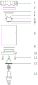
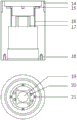
The present embodiment provides an underwater illumination device as shown in fig. 1-9. The embodiment provides including locking lid 1, printing opacity cover 2, 0 type circle of axial seal 3, reflection of light cup 4, lamp pearl clamp bolt 5, with the cyclic annular support piece 31 of the first level of seal chamber lateral wall body coupling, and the cyclic annular support piece 32 of second level, lamp pearl 6, ultraviolet lamp pearl 7, the seal chamber body 8, radial seal O type circle 9, rear end cap 10, rear end cap locking bolt 11, constant current control module group 12, watertight socket 13. An internal thread is arranged inside the locking cover; the outer edge of the upper part of the sealed cabin body is provided with an external thread 14 matched with the locking cover, the sealed cabin body is internally provided with a sealed groove 15, an ultraviolet lamp bead threading hole 16 and a lamp bead threading hole 17, a clamping groove 19 for embedding a lamp bead is arranged on the first horizontal annular supporting piece 31, a threaded hole 20 for installing a lamp bead compression bolt, an ultraviolet lamp bead clamping groove 21 for embedding an ultraviolet lamp bead is arranged on the second horizontal annular supporting piece 32, and a threaded hole 18 for installing a rear end cover locking bolt is arranged at the lower part of the second horizontal annular supporting piece; the rear end cover is provided with a sealing groove 22, a through hole 23 for inserting a bolt, a rectangular hole 24 convenient to disassemble and a threaded hole 25 for installing a watertight socket. The metal sealing cabin body 8 is integrally connected with the first horizontal annular supporting piece 31 and the second horizontal annular supporting piece 32, so that heat of the lighting device and the ultraviolet device is effectively conducted into seawater, and the heat dissipation efficiency is improved.
The lamp beads 6 are placed in the clamping grooves 19 of the sealed cabin body and are fixed by the lamp bead compression bolts 5; ultraviolet lamp pearl 7 is put into draw-in groove 21, and is fixed with special glue, and axial seal O type circle 3 is arranged in the seal groove 15 of the sealed cabin body, and printing opacity cover 2 card goes into the sealed cabin body upper end and presses on axial seal O type circle 3, and locking lid 1 screw in sealed cabin body 8 compresses tightly printing opacity cover 2, and the one end of sealed cabin body 8 can be sealed. The watertight socket 13 is screwed into the threaded hole 25 of the rear end cover, and the watertight socket and the rear end cover 10 form sealing after being screwed; the watertight socket rear end links to each other with constant current module one end contact pin, the other end and the lamp pearl 20 of constant current module, set up the through-hole between ultraviolet lamp pearl draw-in groove 21, the electric connecting element of constant current module through running through the through-hole, if contact pin etc., link to each other with lamp pearl 6 and ultraviolet lamp pearl 7, rear end cap seal groove 22 is put into to radial seal O type circle 9, rear end cap 10 who is equipped with watertight socket 13 and radial seal O type circle 9 inserts in the sealed cabin body 8, rear end cap locking bolt 11 fastens it, the other end of the sealed cabin body 8 can be sealed, solve the waterproof problem of LED light under water. As shown in fig. 5a and 5b, the reflective cup 4 is clamped in the first horizontal annular support 31, and the sidewall of the sealed cavity limits the radial movement of the reflective cup 4; the light reflecting cup 4 is pressed through the light transmitting cover 2, and the axial movement of the light reflecting cup 4 is limited. The light-transmitting 2 cover is made of special quartz glass and is high in strength and light transmittance; the locking cover 1, the sealing cabin body 8 and the rear end cover 10 are made of Hsn70-1, corrosion resistant, easy to process and high in heat conductivity.
The illuminating lamp beads adopt LED lamp bead arrays, high-density integrated lamp beads are preferred, the brightness is high, the independence is strong, and the single bead damage does not influence the illumination of other lamp beads. The ultraviolet lamp beads are preferably monomer lamp beads, the size is small, the irradiation angle is preferably 70 degrees, the effective acting radius is 100mm, and ultraviolet rays with the wavelength in a specific range can be emitted so as to destroy the molecular structure of DNA or RNA in marine organisms and achieve the effect of preventing biological pollution.
The sealed cabin body with illuminating lamp pearl is closely laminated, the sealed cabin body conduct the base of illuminating lamp pearl not only plays sealed guard action, still plays heat transfer cooling effect, directly will the heat that the lamp pearl produced passes to aquatic, has solved the long-time work heat dissipation problem of lamp pearl.
In order to ensure the anti-biological adhesion effect of the transparent cover and reduce unnecessary energy loss, the present embodiment analyzes and processes the number of the ultraviolet lamp beads and the installation angle of the single ultraviolet lamp beads, so as to optimize the combination thereof, as shown in fig. 7 to 9.
Because the illuminating lamp bead generates heat greatly, in order to reduce the influence of high temperature to the translucent cover, consequently make illuminating lamp bead 6 and translucent cover 2 keep certain distance. Because of monomer ultraviolet lamp pearl calorific capacity is less relatively, can neglect its influence to the printing opacity cover, in order to reduce sheltering from of other parts of light under water to the ultraviolet ray simultaneously, the ultraviolet lamp pearl is arranged in the position that is close to the printing opacity cover.
The ultraviolet lamp beads are arranged on the periphery of the illuminating lamp beads, so that the ultraviolet lamp beads are inclined towards the illuminating lamp beads when being installed, and more ultraviolet light penetrates through the light-transmitting cover to play a role in protection. Through data calculation and modeling analysis, one ultraviolet lamp bead cannot meet the ultraviolet light full-coverage protection surface, so that a multi-lamp bead distribution combination mode is adopted. In the embodiment, inside the ultraviolet lamp bead clamping groove 21 for placing the ultraviolet lamp beads 7, the height adjusting elements 33 are arranged near one side or multiple sides inside the sealed cabin, and the height adjusting elements 33 can be screw elements capable of adjusting height through rotation or gaskets capable of being set to bounce or fall through pressing. The height adjusting element comprises a plurality of continuous or discontinuous gears, and the included angle between the bottom surface of the clamping groove of the ultraviolet lamp bead and the horizontal plane is controlled and processed by adjusting the height gears of the height adjusting element, so that the inclination angle of the ultraviolet lamp bead is controlled. Ultraviolet lamp pearl 7 place in ultraviolet lamp pearl draw-in groove 21 aslope, through the high gear of adjustment height adjustment unit, adapt to the equipment that needs different illumination zone demands. Each ultraviolet lamp bead is connected with two leads, the ultraviolet lamp beads and the two leads are welded through soldering tin, and the other ends of the leads are connected with the circuit board through contact pins.
By selecting the cross section analysis of the ultraviolet lamp beads and the illuminating lamp beads, in order to enable the single ultraviolet light source to penetrate through the central point of the upper part of the light-transmitting cover and enable the single ultraviolet light source to illuminate the edge of the inner hole of the locking cover, the light-emitting range of the ultraviolet light source when the proper angle for installing the ultraviolet lamp beads is 19-24 degrees and the critical angle is calculated as shown in figures 8a-8 b. When the installation angle is 19 degrees, the right light source of the ultraviolet lamp bead just penetrates through the center of the light-transmitting cover; when the installation angle is 24 degrees, the light source on the left side of the ultraviolet lamp bead just irradiates the edge of the inner hole of the locking cover.
By selecting the section where the upper surface of the light-transmitting cover is located for analysis, in order to enable the monomer ultraviolet light sources to complement each other without redundancy, the number of ultraviolet lamp beads is finally determined to be at least 5 through modeling analysis, the ultraviolet lamp beads are uniformly distributed on the circumference, and the illumination light-emitting range and the ultraviolet light-emitting range are shown in figure 9.
The technical scheme that this embodiment provided, through the cooperation of ultraviolet luminescence unit and illumination luminescence unit, the integration realizes withstand voltage, corrosion-resistant, and structure simple structure, practicality make things convenient for the assembly, easily maintenance. Through setting up the inclination of adjustable ultraviolet luminescence unit, obtain a plurality of effective ultraviolet luminescence scopes, but wide application in the underwater lighting device of multiple illumination scope demand, no matter be exclusive use or be used for carrying on other equipment, all improved the convenience that the user used. Through the metal sealed cavity, the metal lighting unit supporting piece and the metal ultraviolet unit supporting piece which are integrated, heat of the lighting device and the ultraviolet device is effectively conducted into seawater, and the heat dissipation efficiency is improved.
The above-mentioned embodiments, objects, technical solutions and advantages of the present invention are further described in detail, it should be understood that the above-mentioned embodiments are only examples of the present invention, and are not intended to limit the scope of the present invention, and any modifications, equivalent substitutions, improvements and the like made within the spirit and principle of the present invention should be included in the scope of the present invention.
Claims (10)
1. An underwater lighting device, comprising: the cabin unit, the lighting unit and the power supply unit;
the cabin unit includes: a light transmitting unit, a sealing unit;
the lighting unit includes: at least one illumination light emitting element, at least three ultraviolet light emitting elements;
the sealing unit comprises a sealing cavity, the sealing cavity comprises a first horizontal annular supporting piece and a second horizontal annular supporting piece which are integrally connected with an outer wall, the first horizontal annular supporting piece comprises at least one first clamping groove for placing the lighting and light-emitting element, and the second horizontal annular supporting piece comprises at least three second clamping grooves for placing the ultraviolet light-emitting element; a height adjusting element for adjusting the inclination angle of the ultraviolet light emitting element is arranged at the bottom of each second clamping groove;
the power supply unit includes: and a constant current control module.
2. The underwater lighting apparatus of claim 1, wherein the height adjusting member comprises at least two height steps, and the height steps are selected according to an irradiation angle of the ultraviolet light emitting member and an effective acting radius.
3. The underwater illumination device of claim 2, wherein the ultraviolet light emitting element disposed on the height adjustment element is at an angle of 19 ° to 24 ° to the horizontal.
4. The underwater lighting apparatus of claim 1, wherein the lighting unit includes at least one lighting light emitting unit through hole in one-to-one correspondence with each lighting light emitting unit, at least one ultraviolet light emitting unit through hole in one-to-one correspondence with each ultraviolet light emitting unit; the contact pin passes through the through hole of the illumination light-emitting unit, the through hole of the ultraviolet light-emitting unit is connected with the illumination light-emitting unit and the ultraviolet light-emitting unit, the first end of the through hole of the illumination light-emitting unit is connected to the first clamping groove, and the second end of the through hole of the illumination light-emitting unit is communicated with the cavity where the constant current module is located; and the first end of the ultraviolet light-emitting unit through hole is communicated with the second clamping groove, and the second end of the ultraviolet light-emitting unit through hole is communicated with the cavity where the constant current module is located.
5. The underwater lighting apparatus of claim 1, wherein the sealing unit comprises: the locking cover, the axial seal unit, the sealed cabin body, the radial seal unit, the rear end cover, rear end cover locking unit.
6. The underwater lighting device as claimed in claim 4, wherein the locking cover has a first internal thread therein, the outer edge of the upper portion of the sealed cabin has a first external thread engaged with the locking cover, the sealed cabin has a first sealing groove therein, and the rear end cap has a second sealing groove therein; the axial sealing unit is arranged in a first sealing groove of the sealing cabin body, the radial sealing unit is arranged in a second sealing groove of the rear end cover, and the axial sealing unit, the first sealing groove, the radial sealing unit and the second sealing groove are locked through bolts.
7. The underwater lighting apparatus of claim 5, wherein the sealing unit comprises a socket connection through hole, a third external thread is arranged in the socket connection through hole, and the third external thread is matched and locked with a third internal thread on the socket.
8. The underwater lighting apparatus of claim 1, wherein the light transmissive unit comprises a light transmissive cover, a light reflective cup; the light-transmitting cover is clamped on the sealing cavity, and the locking cover is screwed into the sealing cavity to tightly press the light-transmitting cover; the light reflecting cup is clamped in the first horizontal annular supporting piece, and the side wall of the sealing cavity limits the radial movement of the light reflecting cup; and the light-transmitting cover compresses the light-reflecting cup to limit the axial movement of the light-reflecting cup.
9. The subsea lighting device of claim 8, wherein the ultraviolet lighting unit is disposed between the lighting unit and the light transmissive cover.
10. The underwater illumination device as claimed in claim 1, wherein the ultraviolet light emitting unit is connected to the circuit board by soldering and pins.
Priority Applications (1)
| Application Number | Priority Date | Filing Date | Title |
|---|---|---|---|
| CN202010173813.6A CN111237683B (en) | 2020-03-13 | 2020-03-13 | Underwater lighting equipment |
Applications Claiming Priority (1)
| Application Number | Priority Date | Filing Date | Title |
|---|---|---|---|
| CN202010173813.6A CN111237683B (en) | 2020-03-13 | 2020-03-13 | Underwater lighting equipment |
Publications (2)
| Publication Number | Publication Date |
|---|---|
| CN111237683A true CN111237683A (en) | 2020-06-05 |
| CN111237683B CN111237683B (en) | 2022-05-17 |
Family
ID=70867421
Family Applications (1)
| Application Number | Title | Priority Date | Filing Date |
|---|---|---|---|
| CN202010173813.6A Active CN111237683B (en) | 2020-03-13 | 2020-03-13 | Underwater lighting equipment |
Country Status (1)
| Country | Link |
|---|---|
| CN (1) | CN111237683B (en) |
Citations (11)
| Publication number | Priority date | Publication date | Assignee | Title |
|---|---|---|---|---|
| CN2550636Y (en) * | 2002-06-07 | 2003-05-14 | 中国科学院沈阳自动化研究所 | Underwater lighting lamp |
| CN201866628U (en) * | 2010-10-21 | 2011-06-15 | 邓亦林 | Spot lamp with adjustable light-emitting angle |
| CN202001894U (en) * | 2011-01-20 | 2011-10-05 | 宜兴爱特盟光电科技有限公司 | Light-emitting diode (LED) lamp for optical detection device |
| CN102639927A (en) * | 2009-12-02 | 2012-08-15 | 欧司朗股份有限公司 | Lighting apparatus for a beacon system |
| CN103867969A (en) * | 2012-12-14 | 2014-06-18 | 罗斯蒙特航天公司 | Surveillance device |
| CN105402611A (en) * | 2015-12-15 | 2016-03-16 | 太龙(福建)商业照明股份有限公司 | Depth adjusting device for LED anti-dazzle ring |
| CN206958719U (en) * | 2017-05-17 | 2018-02-02 | 孙利嫚 | A kind of underwater LED lamp cylinder with sterilizing function |
| CN207034729U (en) * | 2017-07-31 | 2018-02-23 | 广东凯西欧照明有限公司 | A kind of infrared illumination device |
| CN208719995U (en) * | 2018-09-26 | 2019-04-09 | 深圳市奋华自动化科技有限公司 | A kind of anti-interference vision light source |
| CN209137771U (en) * | 2018-03-21 | 2019-07-23 | 厦门通秴科技股份有限公司 | Human body recovery health therapy headlamp and system |
| CN209341214U (en) * | 2019-01-29 | 2019-09-03 | 泉州德化县嘉欧利工艺品有限责任公司 | A kind of ceramic lamp with monitoring function |
-
2020
- 2020-03-13 CN CN202010173813.6A patent/CN111237683B/en active Active
Patent Citations (11)
| Publication number | Priority date | Publication date | Assignee | Title |
|---|---|---|---|---|
| CN2550636Y (en) * | 2002-06-07 | 2003-05-14 | 中国科学院沈阳自动化研究所 | Underwater lighting lamp |
| CN102639927A (en) * | 2009-12-02 | 2012-08-15 | 欧司朗股份有限公司 | Lighting apparatus for a beacon system |
| CN201866628U (en) * | 2010-10-21 | 2011-06-15 | 邓亦林 | Spot lamp with adjustable light-emitting angle |
| CN202001894U (en) * | 2011-01-20 | 2011-10-05 | 宜兴爱特盟光电科技有限公司 | Light-emitting diode (LED) lamp for optical detection device |
| CN103867969A (en) * | 2012-12-14 | 2014-06-18 | 罗斯蒙特航天公司 | Surveillance device |
| CN105402611A (en) * | 2015-12-15 | 2016-03-16 | 太龙(福建)商业照明股份有限公司 | Depth adjusting device for LED anti-dazzle ring |
| CN206958719U (en) * | 2017-05-17 | 2018-02-02 | 孙利嫚 | A kind of underwater LED lamp cylinder with sterilizing function |
| CN207034729U (en) * | 2017-07-31 | 2018-02-23 | 广东凯西欧照明有限公司 | A kind of infrared illumination device |
| CN209137771U (en) * | 2018-03-21 | 2019-07-23 | 厦门通秴科技股份有限公司 | Human body recovery health therapy headlamp and system |
| CN208719995U (en) * | 2018-09-26 | 2019-04-09 | 深圳市奋华自动化科技有限公司 | A kind of anti-interference vision light source |
| CN209341214U (en) * | 2019-01-29 | 2019-09-03 | 泉州德化县嘉欧利工艺品有限责任公司 | A kind of ceramic lamp with monitoring function |
Also Published As
| Publication number | Publication date |
|---|---|
| CN111237683B (en) | 2022-05-17 |
Similar Documents
| Publication | Publication Date | Title |
|---|---|---|
| CA2497545C (en) | Compact light emitting diode retrofit lamp and method for traffic signal lights | |
| CN101730820B (en) | Lighting method and system | |
| US7488097B2 (en) | LED lamp module | |
| US9518715B2 (en) | Lighting devices that comprise one or more solid state light emitters | |
| CN201795384U (en) | Pressure buckled LED spot lamp | |
| CN101929625A (en) | Light emitting diode (LED) lamp | |
| CN201827727U (en) | Energy-saving light-emitting diode (LED) corn lamp | |
| CN102454916A (en) | Light-emitting diode (LED) lamp | |
| CN102563388B (en) | All-round type LED (Light-Emitting Diode) lamp | |
| CN102052589B (en) | Light-emitting diode lamp | |
| CN111237683B (en) | Underwater lighting equipment | |
| CN110925678A (en) | Self-dimming lamp special for underwater lighting | |
| CN201209830Y (en) | LED lighting fixture adjusting mechanism | |
| CN206036941U (en) | LED optics external member | |
| CN201715279U (en) | Global LED bulb | |
| CN209926107U (en) | LED floodlight | |
| CN210197035U (en) | LED corn lamp | |
| CN219140532U (en) | Light underwater laser lamp | |
| CN100523591C (en) | LED light, lamp holder and other two LED lights | |
| CN107524936A (en) | Light fixture | |
| CN210004174U (en) | novel LED bulb | |
| CN218178636U (en) | Lamp set | |
| CN213810342U (en) | Lawn lamp with adjustable angle | |
| CN210831732U (en) | Mining lamp with variable light distribution | |
| CN206112812U (en) | Effectual three proofings LED lamps and lanterns of light -emitting |
Legal Events
| Date | Code | Title | Description |
|---|---|---|---|
| PB01 | Publication | ||
| PB01 | Publication | ||
| SE01 | Entry into force of request for substantive examination | ||
| SE01 | Entry into force of request for substantive examination | ||
| TA01 | Transfer of patent application right | ||
| TA01 | Transfer of patent application right |
Effective date of registration: 20220422 Address after: 572024 area C310, third floor, phase II standard plant, yazhouwan science and Technology City, Yazhou District, Sanya City, Hainan Province Applicant after: Research Institute of Hainan Zhejiang University Address before: 316021 No.1, Zheda Road, Dinghai District, Zhoushan City, Zhejiang Province Applicant before: ZHEJIANG University |
|
| GR01 | Patent grant | ||
| GR01 | Patent grant |