CN111237314B - Tolerance compensation device comprising a coupling device - Google Patents
Tolerance compensation device comprising a coupling device Download PDFInfo
- Publication number
- CN111237314B CN111237314B CN201911138496.8A CN201911138496A CN111237314B CN 111237314 B CN111237314 B CN 111237314B CN 201911138496 A CN201911138496 A CN 201911138496A CN 111237314 B CN111237314 B CN 111237314B
- Authority
- CN
- China
- Prior art keywords
- tolerance compensation
- compensation device
- coupling
- tolerance
- groove
- Prior art date
- Legal status (The legal status is an assumption and is not a legal conclusion. Google has not performed a legal analysis and makes no representation as to the accuracy of the status listed.)
- Active
Links
- 230000008878 coupling Effects 0.000 title claims abstract description 75
- 238000010168 coupling process Methods 0.000 title claims abstract description 75
- 238000005859 coupling reaction Methods 0.000 title claims abstract description 75
- 230000005294 ferromagnetic effect Effects 0.000 claims description 4
- 230000007704 transition Effects 0.000 claims description 4
- 238000000034 method Methods 0.000 description 5
- 230000003014 reinforcing effect Effects 0.000 description 4
- 230000000295 complement effect Effects 0.000 description 3
- 230000008569 process Effects 0.000 description 3
- 238000004026 adhesive bonding Methods 0.000 description 2
- 230000005540 biological transmission Effects 0.000 description 2
- 230000006835 compression Effects 0.000 description 2
- 238000007906 compression Methods 0.000 description 2
- 238000003466 welding Methods 0.000 description 2
- 235000001674 Agaricus brunnescens Nutrition 0.000 description 1
- 229910000831 Steel Inorganic materials 0.000 description 1
- 230000008901 benefit Effects 0.000 description 1
- 238000010276 construction Methods 0.000 description 1
- 230000001419 dependent effect Effects 0.000 description 1
- 239000003302 ferromagnetic material Substances 0.000 description 1
- 239000003292 glue Substances 0.000 description 1
- 238000002347 injection Methods 0.000 description 1
- 239000007924 injection Substances 0.000 description 1
- 230000003993 interaction Effects 0.000 description 1
- 239000000463 material Substances 0.000 description 1
- 230000000717 retained effect Effects 0.000 description 1
- 239000010959 steel Substances 0.000 description 1
Images


Classifications
-
- F—MECHANICAL ENGINEERING; LIGHTING; HEATING; WEAPONS; BLASTING
- F16—ENGINEERING ELEMENTS AND UNITS; GENERAL MEASURES FOR PRODUCING AND MAINTAINING EFFECTIVE FUNCTIONING OF MACHINES OR INSTALLATIONS; THERMAL INSULATION IN GENERAL
- F16B—DEVICES FOR FASTENING OR SECURING CONSTRUCTIONAL ELEMENTS OR MACHINE PARTS TOGETHER, e.g. NAILS, BOLTS, CIRCLIPS, CLAMPS, CLIPS OR WEDGES; JOINTS OR JOINTING
- F16B5/00—Joining sheets or plates, e.g. panels, to one another or to strips or bars parallel to them
- F16B5/02—Joining sheets or plates, e.g. panels, to one another or to strips or bars parallel to them by means of fastening members using screw-thread
- F16B5/0216—Joining sheets or plates, e.g. panels, to one another or to strips or bars parallel to them by means of fastening members using screw-thread the position of the plates to be connected being adjustable
- F16B5/0233—Joining sheets or plates, e.g. panels, to one another or to strips or bars parallel to them by means of fastening members using screw-thread the position of the plates to be connected being adjustable allowing for adjustment perpendicular to the plane of the plates
-
- F—MECHANICAL ENGINEERING; LIGHTING; HEATING; WEAPONS; BLASTING
- F16—ENGINEERING ELEMENTS AND UNITS; GENERAL MEASURES FOR PRODUCING AND MAINTAINING EFFECTIVE FUNCTIONING OF MACHINES OR INSTALLATIONS; THERMAL INSULATION IN GENERAL
- F16B—DEVICES FOR FASTENING OR SECURING CONSTRUCTIONAL ELEMENTS OR MACHINE PARTS TOGETHER, e.g. NAILS, BOLTS, CIRCLIPS, CLAMPS, CLIPS OR WEDGES; JOINTS OR JOINTING
- F16B37/00—Nuts or like thread-engaging members
- F16B37/08—Quickly-detachable or mountable nuts, e.g. consisting of two or more parts; Nuts movable along the bolt after tilting the nut
-
- F—MECHANICAL ENGINEERING; LIGHTING; HEATING; WEAPONS; BLASTING
- F16—ENGINEERING ELEMENTS AND UNITS; GENERAL MEASURES FOR PRODUCING AND MAINTAINING EFFECTIVE FUNCTIONING OF MACHINES OR INSTALLATIONS; THERMAL INSULATION IN GENERAL
- F16B—DEVICES FOR FASTENING OR SECURING CONSTRUCTIONAL ELEMENTS OR MACHINE PARTS TOGETHER, e.g. NAILS, BOLTS, CIRCLIPS, CLAMPS, CLIPS OR WEDGES; JOINTS OR JOINTING
- F16B5/00—Joining sheets or plates, e.g. panels, to one another or to strips or bars parallel to them
- F16B5/02—Joining sheets or plates, e.g. panels, to one another or to strips or bars parallel to them by means of fastening members using screw-thread
- F16B5/0241—Joining sheets or plates, e.g. panels, to one another or to strips or bars parallel to them by means of fastening members using screw-thread with the possibility for the connection to absorb deformation, e.g. thermal or vibrational
-
- F—MECHANICAL ENGINEERING; LIGHTING; HEATING; WEAPONS; BLASTING
- F16—ENGINEERING ELEMENTS AND UNITS; GENERAL MEASURES FOR PRODUCING AND MAINTAINING EFFECTIVE FUNCTIONING OF MACHINES OR INSTALLATIONS; THERMAL INSULATION IN GENERAL
- F16B—DEVICES FOR FASTENING OR SECURING CONSTRUCTIONAL ELEMENTS OR MACHINE PARTS TOGETHER, e.g. NAILS, BOLTS, CIRCLIPS, CLAMPS, CLIPS OR WEDGES; JOINTS OR JOINTING
- F16B27/00—Bolts, screws, or nuts formed in integral series but easily separable, particularly for use in automatic machines
-
- F—MECHANICAL ENGINEERING; LIGHTING; HEATING; WEAPONS; BLASTING
- F16—ENGINEERING ELEMENTS AND UNITS; GENERAL MEASURES FOR PRODUCING AND MAINTAINING EFFECTIVE FUNCTIONING OF MACHINES OR INSTALLATIONS; THERMAL INSULATION IN GENERAL
- F16B—DEVICES FOR FASTENING OR SECURING CONSTRUCTIONAL ELEMENTS OR MACHINE PARTS TOGETHER, e.g. NAILS, BOLTS, CIRCLIPS, CLAMPS, CLIPS OR WEDGES; JOINTS OR JOINTING
- F16B43/00—Washers or equivalent devices; Other devices for supporting bolt-heads or nuts
-
- F—MECHANICAL ENGINEERING; LIGHTING; HEATING; WEAPONS; BLASTING
- F16—ENGINEERING ELEMENTS AND UNITS; GENERAL MEASURES FOR PRODUCING AND MAINTAINING EFFECTIVE FUNCTIONING OF MACHINES OR INSTALLATIONS; THERMAL INSULATION IN GENERAL
- F16B—DEVICES FOR FASTENING OR SECURING CONSTRUCTIONAL ELEMENTS OR MACHINE PARTS TOGETHER, e.g. NAILS, BOLTS, CIRCLIPS, CLAMPS, CLIPS OR WEDGES; JOINTS OR JOINTING
- F16B5/00—Joining sheets or plates, e.g. panels, to one another or to strips or bars parallel to them
- F16B5/06—Joining sheets or plates, e.g. panels, to one another or to strips or bars parallel to them by means of clamps or clips
- F16B5/0607—Joining sheets or plates, e.g. panels, to one another or to strips or bars parallel to them by means of clamps or clips joining sheets or plates to each other
- F16B5/0621—Joining sheets or plates, e.g. panels, to one another or to strips or bars parallel to them by means of clamps or clips joining sheets or plates to each other in parallel relationship
- F16B5/0628—Joining sheets or plates, e.g. panels, to one another or to strips or bars parallel to them by means of clamps or clips joining sheets or plates to each other in parallel relationship allowing for adjustment parallel or perpendicular to the plane of the sheets or plates
-
- F—MECHANICAL ENGINEERING; LIGHTING; HEATING; WEAPONS; BLASTING
- F16—ENGINEERING ELEMENTS AND UNITS; GENERAL MEASURES FOR PRODUCING AND MAINTAINING EFFECTIVE FUNCTIONING OF MACHINES OR INSTALLATIONS; THERMAL INSULATION IN GENERAL
- F16B—DEVICES FOR FASTENING OR SECURING CONSTRUCTIONAL ELEMENTS OR MACHINE PARTS TOGETHER, e.g. NAILS, BOLTS, CIRCLIPS, CLAMPS, CLIPS OR WEDGES; JOINTS OR JOINTING
- F16B5/00—Joining sheets or plates, e.g. panels, to one another or to strips or bars parallel to them
- F16B5/06—Joining sheets or plates, e.g. panels, to one another or to strips or bars parallel to them by means of clamps or clips
- F16B5/0607—Joining sheets or plates, e.g. panels, to one another or to strips or bars parallel to them by means of clamps or clips joining sheets or plates to each other
- F16B5/0621—Joining sheets or plates, e.g. panels, to one another or to strips or bars parallel to them by means of clamps or clips joining sheets or plates to each other in parallel relationship
- F16B5/0635—Joining sheets or plates, e.g. panels, to one another or to strips or bars parallel to them by means of clamps or clips joining sheets or plates to each other in parallel relationship fastened over the edges of the sheets or plates
Abstract
The invention relates to a tolerance compensation device comprising a coupling device for compensating for tolerances between two components to be connected by a connecting screw, the device comprising a base element and a compensation element that can be removed from the base element, the base element and the compensation element forming a passage for the connecting screw defining an axial direction, and the coupling device of the device being designed to couple the device to a carrier element and to guide the device along the carrier element.
Description
Technical Field
The invention relates to a device for compensating for tolerances between two components to be connected by means of a connecting screw, comprising a base element and a compensating element which can be removed from the base element, the base element and the compensating element forming a passage for the connecting screw, which passage defines an axial direction.
Background
Such devices, also referred to as tolerance compensation devices, are known in principle and are used, for example, in the construction of motor vehicles to compensate for tolerances in the spacing between a first component (e.g. a carrier structure, a vehicle body or the like) and a second component (e.g. a luggage rack, an instrument panel, a door, a hood, a seat, a trunk lid or the like) to be mounted thereon, the compensation being in the axial direction. In this case, the device is optionally pre-mounted on the first component or the second component, depending on the mounting specifications. For this purpose, the device is fastened to the first component, for example, by a base element. The compensating element is then moved out of the base element in the direction of the second component until the end face of the compensating element rests on the second component. The components can now be clamped to each other by means of a connecting screw extending through the components and the device.
The removal of the compensating element from the base element can take place, for example, by rotating the compensating element out of the base element. For this purpose, the base element and the compensation element can be in a threaded engagement, preferably in a left-handed threaded engagement, so that the compensation element automatically rotates out of the base element when the connection screw is screwed into the associated nut element. A torque transmission device, for example in the form of a spring element, is usually provided in the passage of the compensating element in order to transmit the torque of the connecting screw to the compensating element.
Prior to use of the device as intended, the device is stored in a storage container in which they are generally oriented as desired. In order to be able to mount the device in the desired manner, a correct orientation of the device relative to the first component is necessary. Previously, this was achieved by a manual set-up procedure in which the device was removed from the storage container and then secured to the first component by hand. Thus, such procedures are time consuming and ultimately also expensive.
Disclosure of Invention
The problem addressed by the present invention is to provide a device for tolerance compensation which is suitable for an automatic setting process.
In order to solve this problem, a device for compensating tolerances is provided with the features of claim 1. The tolerance compensation device according to the invention is characterized by coupling means which are designed to couple the device to the carrier element and to guide the device along the carrier element.
The invention is based on the following general idea: a tolerance compensation device is provided, which has a coupling device that allows coupling of the tolerance compensation device to a carrier element, by means of which the tolerance compensation device can be provided in a correctly oriented manner to a setting robot, so that said robot attaches the tolerance compensation device to a first component of a component to be connected in a desired manner. The setting process can thus be automated, so that it can be carried out more easily, precisely, reproducibly and finally also inexpensively than a manual setting process.
Another advantage of the invention is that by means of the coupling means, the device can be arranged, i.e. oriented in a defined manner, stored in a cassette and guided. Such storage may be advantageous even during manual set-up, since each device may be removed from the cartridge in a correctly oriented manner.
Advantageous embodiments of the invention can be found in the dependent claims, the description and the drawings.
According to a particularly simple embodiment of the device, the coupling means are formed on the base element. In this case, the base element can have at least one fastening means for fastening the device to the first component, which fastening means can be designed, for example, in the form of a retaining clip, a locking portion, a clamping device or the like.
Alternatively, the coupling means can also be formed on a holding element for holding the base element. Similar to the base element, the holding element can also have at least one fastening device of the aforementioned type.
It is also conceivable that the coupling device is not provided on the base element or the holding element, but instead on the compensating element.
It goes without saying that, in addition to or as an alternative to the frictional and/or interlocking fastening, the base element or the holding element may also be integrally fastened to the first component, for example by gluing or welding the elements in place on the first component.
When the coupling means have a longitudinal extension which is oriented at least substantially parallel to the axial direction, the means coupled to the carrier element undergo a particularly advantageous orientation during the subsequent setting. In principle, depending on the use case, the longitudinal extension of the coupling device can also be oriented transversely, in particular at right angles, to the axial direction.
According to one embodiment, the coupling means comprises a groove defining at least one undercut. As a result, the coupling means can engage behind the complementary ribs of the carrier element and the device can be guided in any spatial direction, without in this case the device accidentally disengaging from the carrier element. The ribs of the carrier element can engage behind particularly well when the groove is a T-groove, an L-groove, a circular groove, a dovetail groove or the like.
In order to make it possible for the device to be easily engaged with the carrier element, the slot advantageously has a widened portion at least one of its longitudinal ends. The widened longitudinal end of the slot facilitates to some extent the screwing of the device onto the carrier element. In this case, the longitudinal end of the slot is on a longitudinal end of the coupling means, which longitudinal end defines the coupling means in the direction of its longitudinal extension.
Instead of a groove, the coupling device may also comprise an arm which defines at least one undercut and extends radially or tangentially away from the outer wall of the base element or the outer wall of the retaining element. It goes without saying that in this case the carrier element has a complementary groove which engages behind the undercut of the arm in order to couple the device to the carrier element.
In order to make it possible for the device to be easily engaged with the carrier element, i.e. to be easily screwed onto the carrier element, the coupling device advantageously has a tapered portion on at least one of its longitudinal ends. As a result, the longitudinal ends define the coupling means in the direction of their longitudinal extension.
A particularly good engagement between the device and the carrier element can be achieved in that the arm at its free end transitions into at least one angled hook portion, which faces away from the outer wall of the base element or the outer wall of the carrier element, so that the coupling device as a whole has a cross-section which is, for example, T-shaped or L-shaped. Instead of the hook portion arms, it is also possible to have differently designed undercut ends on their free ends, which are facing away from the outer wall of the base element or the outer wall of the carrier element, for example so that the coupling device has a circular cross section, in particular a mushroom shape, a dovetail shape or the like.
In the case of a coupling device having arms with differently undercut hook portions or end portions, the coupling portion in some respects forms a slot nut which can be guided in a slot of the carrier element when the device is in the coupled state.
In order to enable the setting robot to better grip the device, but also to position and orient the device precisely by the setting robot, guide elements are advantageously provided on the coupling device. For the same purpose, a magnetizable, in particular ferromagnetic, element may additionally or alternatively be provided on the coupling element, in particular embedded in the coupling element.
Advantageously, at least two guide elements are advantageously provided on opposite longitudinal sides of the coupling device to facilitate correct orientation of the device in the setting robot.
In addition, the guide elements formed on the coupling device can also be used for orienting and/or guiding the device on the carrier element.
The guide elements can be designed, for example, in the form of prismatic or pentroof-like projections on the coupling device. However, it is also conceivable for the guide element to be a recess in the coupling device.
The invention also relates to a system comprising at least one device of the aforementioned type, and a carrier element for receiving and guiding the at least one device. The device is preferably movably guided relative to the carrier element by the coupling means, and therefore the device can be easily provided to the setting robot.
A particularly high level of freedom in design is produced when the carrier element is at least partially flexible. For certain use cases, the carrier element may alternatively or additionally be at least partially rigid. In addition, it is conceivable that the carrier element is tubular such that the carrier element surrounds the coupled device in the radial direction.
Drawings
The invention is described below in a purely exemplary manner by means of possible embodiments with reference to the accompanying drawings, in which:
FIGS. 1A and 1B are perspective views of a tolerance compensating device according to a first embodiment of the present invention;
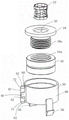
FIG. 2 is an exploded view of the tolerance compensating device of FIG. 1;
FIG. 3A is a perspective view of the tolerance compensating device of FIG. 1 in a state partially pre-mounted on a component;
FIG. 3B is a plan view from below of the tolerance compensation device of FIG. 1 in a partially pre-mounted state on a component;
FIG. 4 is a plan view from below of the tolerance compensating device of FIG. 1 in a state fully pre-mounted on the component;
FIGS. 5A and 5B are perspective views of a plurality of tolerance compensation devices of FIG. 1 threaded onto a T-shaped carrier element;
6A-6D are various views of the plurality of tolerance compensation devices of FIG. 1 threaded onto the flexible carrier element;
FIG. 7 shows a tolerance compensating device according to a second embodiment of the present invention;
FIG. 8 shows a cartridge for receiving the tolerance compensation device according to FIG. 1 or 7;
FIG. 9 is an exploded view of a tolerance compensating device according to a third embodiment;
FIG. 10 is a perspective view of the tolerance compensating device of FIG. 9, including a first design variation of the coupling device;
FIG. 11 is a perspective view of the tolerance compensating device of FIG. 9, including a second design variation of the coupling device;
FIG. 12 is a plan view of a tolerance compensation device according to FIG. 10 or 11, coupled to a carrier element;
FIG. 13 is a perspective view of the tolerance compensation device of FIG. 9, including a third design variation of the coupling device;
FIG. 14 is a perspective view of the tolerance compensating device of FIG. 9, including a fourth design variation of the coupling device;
FIG. 15 is a plan view of a tolerance compensation device according to FIG. 13 or 14, coupled to a carrier element;
FIG. 16 is a perspective view of a tolerance compensating device according to a fourth embodiment;
FIG. 17 is a plan view of a tolerance compensation device according to FIG. 16, coupled to a carrier element; and
FIG. 18 is a perspective view of a system including the plurality of tolerance compensation devices of FIG. 1 and two carrier elements.
Detailed Description
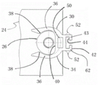
In fig. 1 to 4, a tolerance compensation device 14 according to a first embodiment is shown. The tolerance compensation device 14 includes a base member 16 and a compensation member 18 in left hand threaded engagement therewith. For this purpose, the base element 16 forms a left-hand internal thread 16a, while the compensation element 18 has a correspondingly formed external thread 18a. The thread axes of the internal thread 16a and the external thread 18a define an axial direction.
The base element 16 and the compensation element 18 form a passage 20 for a connecting screw (not shown), which extends in the axial direction. A spring element 22 is inserted into the portion of the passage 20 defined by the compensation element 18, which spring element is provided for producing a frictional connection between a connection screw extending through the passage 20 and the compensation element 18. The spring element 22 transmits the torque of the connection screw to the compensating element and is therefore also referred to as a torque transmission device.
The connecting screw is used to tighten two parts spaced apart from each other, of which the first part 24 is shown in fig. 2. A nut element 26 for a connection screw is non-rotatably attached to the first part 24.
In the present exemplary embodiment, the nut element 26 is a compression nut which is pressed into a correspondingly provided receiving bore 28 of the first component 24. In the present context, the term "compression nut" is also understood to mean press-in nuts, blind rivet nuts, flared nuts, drive nuts, etc. Furthermore, it is conceivable to fasten the nut element 26 to the first component 24 in another way, for example by gluing or welding.
The tolerance compensation device 14 further comprises a retaining element 30 made of plastic, in which the base element 16 is non-rotatably retained. In the present exemplary embodiment, the base element 16 is pressed into the holding element 30. However, it is also conceivable to glue the base element 16 into the retaining element 30, or to shrink or injection mold the retaining element 30 onto the base element 16. To be precise, the base element 16 is fitted in a holding section 32 of the holding element 30, which section extends substantially at right angles to the axial direction.
Furthermore, the holding element 30 forms a locking portion 34, which locking portion 34 also extends substantially at right angles to the axial direction. The locking portion 34 has an axial spacing from the retaining portion 32 which is adapted to the thickness of the first component 24.
The locking portion 34 comprises two locking arms 36 spaced apart from each other, the two locking arms 36 being slightly bent towards each other and defining a receiving portion for the nut element 26 between the arms. The locking arms 36 have a certain elasticity so that they can splay against a restoring force when pushed onto the nut element 26 in the radial direction and spring back into their rest position (fig. 4) once the nut element 26 is received in the receiving portion. In order to prevent the locking portion 34 from being unintentionally disengaged from the received nut element 26, the locking arms 36 have mutually facing locking projections 38 in the region of their free ends. In order to reinforce the locking arm 36, the arms are connected at their bottom region by a reinforcing element 40, which reinforcing element 40 projects partly above the nut element 26 received in the receiving portion.
As shown in FIGS. 3 and 4, to pre-install the tolerance compensation device 14 on the first component 24, the tolerance compensation device 14 is slid laterally (i.e., in a radial direction) onto the first component 24 such that the first component is received between the retaining portion 32 and the locking portion 34 is locked to the nut member 26. To facilitate the sliding of the tolerance-compensating device 14 onto the first component 24, a lead-in groove 41 is formed both in the region of the free end of the locking arm 36 and in a corresponding region of the retaining portion 32.
In the pre-installed state, the tolerance compensation device 14 does not necessarily have to be mounted on the component 24 without play. Instead, a certain play of the tolerance compensation device 14 locked onto the nut element 26, at least in the radial direction, but possibly also in the axial direction, is desired, since this thus facilitates the subsequent screwing together of the components, in particular the orientation of the tolerance compensation device 14 with the connection screw.
To screw the components together, a connecting screw is inserted through a corresponding hole (not shown) in the components and is guided (from above in fig. 1) through the passage 20 in the tolerance compensation device 14 and screwed into the nut element 26. Due to the opposite threading of the connection screw and the tolerance compensation device 14, the compensation element 18 is rotated out of the base element 16 by the frictional connection produced by the spring element 22 when the connection screw is screwed into the nut element 26 until it abuts against a second component (not shown). From this point in time, the distance between the components is bridged by the extended tolerance compensation device 14 and the components can be clamped together by tightening the connecting screw.
The holding portion 32 and the locking portion 34 are connected to each other by a connecting portion 42, which connecting portion 42 extends in the axial direction and to some extent forms a skeleton of the holding element 30. The connecting portion 42 has a rectangular parallelepiped basic shape, and a T-shaped groove 44 is formed on a rear side thereof facing away from the lock arm 36. The connecting portion 42 forms a coupling means 43, the function of which is discussed in more detail below.
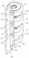
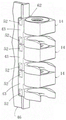
By means of the T-shaped groove 44, the tolerance compensation device 14 can be slid onto a correspondingly formed T-shaped carrier element 46 for transport and/or storage purposes, as shown in fig. 5, by means of three tolerance compensation devices 14.
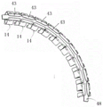
Alternatively, the T-slot 44 allows the tolerance compensation device 14 to be screwed onto a flexible carrier element in the form of a carrier strip 48. Fig. 6 shows such a carrier strip 48 with a number of tolerance compensation devices 14 screwed thereon. Such a configuration is suitable, for example, for supplying the tolerance compensation device 14 to a setting robot for automatic pre-mounting of the tolerance compensation device 14 on one or more components 24.
In principle, this setting robot may be a gripping robot. Alternatively or additionally, however, the setting robot may also have a magnet for holding the tolerance compensation device 14. For interaction with the magnets of the robot, an insert 50 made of magnetizable (in particular ferromagnetic) material, for example steel plate, is embedded in the holding element 30, in the present embodiment in the region between the T-shaped groove 44 and the reinforcing element 40. Furthermore, a magnetizable, in particular ferromagnetic element can be provided on the coupling device 43 and advantageously embedded in the coupling device 43 (not shown in the figures).
In addition, two axially spaced apart prism-like or pentroof-like guide elements 52 are provided on opposite outer sides of the connecting portion 42, which elements serve for additionally guiding the tolerance compensation device 14 in a carrier element in the form of a cassette 54 (fig. 8).
Fig. 7 shows a tolerance compensation device 14 according to a second exemplary embodiment, which finally differs from the first exemplary embodiment described above only in that the retaining element 30 does not have a T-shaped groove 44, but instead an insert 50 made of ferromagnetic material, which engages in the rear side of the connecting part 42 facing away from the locking arm 36, is inserted. As mentioned above, the guide element 52 serves to guide the tolerance compensation device 14 in the cassette 54.
Fig. 9 to 15 show a tolerance compensation device 14 according to a third embodiment, which differs from the tolerance compensation device 14 according to the first embodiment in the design of both the holding element 30 and the coupling device 43. The holding element 30 of the tolerance compensating device 14 according to the third embodiment is substantially annular and has two clamping arms 56 which project from the holding element 30 in the axial direction. The clamping arms 56 serve to fasten the tolerance compensation device 14 on a correspondingly formed first component.
Fig. 16 and 17 show a tolerance compensation device 14 according to a fourth embodiment, which differs from the tolerance compensation device 14 according to the third embodiment only in the design of the holding element 30 and the coupling device 43. In the tolerance compensating device 14 according to the fourth embodiment, the retaining clip 57 is attached to the retaining element 30. A nut element (not visible in the figures) for the attachment screw is stored in the retaining clip 57. The retaining clip 57 also serves to clamp the tolerance compensation device 14 to the first component.
The design of the associated coupling means 43 of the tolerance compensation device 14 according to the third and fourth embodiments is explained in detail below with reference to the associated drawings.
The coupling means 43 are designed to couple the tolerance compensation device 14 to the carrier elements 46,48,54 such that the tolerance compensation device 14 is movable along the carrier elements 46,48, 54. In this case, the carrier element may be a rigid carrier element 46 (fig. 5A and 5B) or a flexible carrier element 48 (fig. 6A to 6D). Furthermore, a combination of rigid carrier elements 46 and flexible carrier elements 48 is also conceivable, as shown for example in fig. 18. Furthermore, a tubular carrier element 54 is also conceivable, which radially surrounds (fig. 8) the coupled tolerance compensation device 14. Such a tubular carrier element 54 can be used in particular as a storage box for a plurality of tolerance compensation devices 14.
In all these cases, the carrier elements 46,48,54 and the at least one tolerance compensation device 14 coupled thereto form a system 58 in which the carrier elements 46,48,54 serve to receive and guide the at least one tolerance compensation device 14.
In the case where the system 58 comprises a plurality of different carrier elements 46,48, as shown in fig. 18, the individual carrier elements 46,48 may transition into each other to continuously guide the tolerance compensation device 14. In this case, both the coupling device 43 and the pentroof-like guide element 52 formed on the coupling device 43 contribute to guiding the individual tolerance compensation device 14. In the embodiment shown in fig. 18, the coupling means 43 serve for guiding the associated tolerance compensation means 14 on the flexible carrier element 48, while the guide element 52 serves for guiding the tolerance compensation element 14 on the rigid carrier element 46.
The different coupling means 43 will be explained in more detail below. In the figures, the coupling means 43 are formed in each case on the holding element 30. However, it is also conceivable to provide the coupling device 43 on the base element 16 or even on the compensating element 18.
As can be seen from the figures, the coupling means 43 have in each case a longitudinal extension which is oriented at least substantially parallel to the passage 20 defining the axial direction. In principle, the longitudinal extension of the coupling device 43 can also be oriented transversely, in particular at right angles, to the axial direction.
The tolerance compensation devices 14 shown in fig. 1 to 6D and 18 each have a coupling device 43 which comprises a groove 44 which defines at least one undercut 60. In the embodiment shown in fig. 1 to 6D and 18, the groove 44 has in each case two undercuts 60 and is therefore designed as a T-groove. However, the groove 44 may also be designed as an L-shaped groove, a circular groove, a dovetail groove or the like.
In order to make it possible for the tolerance compensation device 14 to be screwed more easily to the carrier elements 46,48,54, the slot 44 has a widened portion 64 at each of the opposite longitudinal ends 62.
According to another embodiment, the coupling means 43 may also be designed in the form of an arm 66, which arm 66 defines at least one undercut 60. The arms 66 may extend radially outward from an outer wall 68 of the retaining element 30 (fig. 9-15). According to a variant shown in fig. 16 and 17, the arms 66 can also extend tangentially away from the outer wall 68 of the holding element 30.
In case the coupling means 43 are provided on the base element 16 or the compensating element 18, the arms 66 may extend radially or tangentially away from the associated outer wall of the base element 16 or the compensating element 18.
As can be seen in fig. 9 to 11, and in particular in the cross-sectional view in fig. 12, the arms 66 defining the undercut 60 may have a circular or mushroom-shaped cross-section. Alternatively, the arms 66 may also transition into at least one angled hook portion 70 on their free end facing away from the outer wall 68, such that the coupling device 43 as a whole has a T-shaped cross-section (fig. 15) or an L-shaped cross-section (fig. 17). However, other cross-sectional shapes of the coupling means 43, such as a dovetail-shaped cross-section, are also conceivable. It goes without saying that the coupling means 43 are guided in complementary grooves 71 of the carrier elements 46,48,54 when the tolerance compensation device 14 is in the coupled state.
In order to make it easier to screw the tolerance compensation device 14, the tolerance compensation device 14 shown in fig. 9 to 17 has a tapered portion 72 at each of its longitudinal ends 62.
In order to enable a setting robot (not shown in the figures) to better grip and orient the tolerance compensation device 14, a guide element 52 can be provided on the coupling device 43. As can be easily seen in fig. 1A and 1B, the guide element 52 may protrude on the coupling device 43 in the manner of a four-pitched roof. However, it is also possible for the guide element 52 to be formed on the coupling device 43 in the form of a recess (fig. 9, 10 and 13).
List of reference numerals
14. Tolerance compensation device
16. Base element
18. Compensation element
16a internal thread
18a external thread
20. Vias
22. Spring element
24. First part
26. Nut element
28. Receiving hole
30. Holding element
32. Holding part
34. Locking part
36. Locking arm
38. Locking projection
40. Reinforcing element
41. Lead-in groove
42. Connecting part
43. Coupling device
44 T-shaped groove
46 T-shaped bearing piece
48. Carrier strip
50. Insert piece
52. Guiding element
54. Box
56. Clamping arm
57. Retaining clip
58. System for controlling a power supply
60. Undercut
62. Longitudinal ends
64. Widened portion
66. Arm(s)
68. Outer wall
70. Hook part
71. Trough
72. Tapered section
Claims (18)
1. Tolerance compensation device (14) for compensating tolerances between two components to be connected by a connection screw, comprising a base element (16) and a compensation element (18) which can be moved out of the base element (16), the base element (16) and the compensation element (18) forming a passage (20) for the connection screw defining an axial direction, characterized by further comprising a coupling device (43) for coupling the tolerance compensation device (14) to a carrier element (46, 48, 54) and guiding the device (14) along the carrier element (46, 48, 54),
a guide element (52) is arranged on the coupling device (43), said guide element (52) being used to precisely position and orient the tolerance compensation device by a setting robot.
2. Tolerance compensation device (14) according to claim 1, characterized in that the coupling means (43) are formed on the base element (16).
3. Tolerance compensation device (14) according to claim 1, characterized in that the coupling means (43) are formed on a holding element (30) for holding the base element (16).
4. Tolerance compensation device (14) according to claim 1, characterized in that the coupling device (43) has a longitudinal extension which is oriented at least substantially parallel to the axial direction.
5. Tolerance compensation device (14) according to claim 1, characterized in that the coupling means (43) comprise a groove (44) defining at least one undercut (60).
6. Tolerance compensation device (14) according to claim 5, characterized in that the groove (44) is a T-groove, an L-groove, a circular groove, a dovetail groove or the like.
7. Tolerance compensation device (14) according to claim 5, characterized in that the groove (44) has a widened portion (64) on at least one of its longitudinal ends (62).
8. Tolerance compensation device (14) according to claim 1, characterized in that the coupling device (43) comprises an arm (66), the arm (66) defining at least one undercut (60) and extending radially or tangentially from an outer wall (68) of the base element (16).
9. Tolerance compensating device (14) according to claim 3, characterized in that the coupling device (43) comprises an arm (66), the arm (66) defining at least one undercut (60) and extending radially or tangentially from an outer wall (68) of the holding element (30).
10. Tolerance compensation device (14) according to claim 8, characterized in that the coupling device (43) has a tapered portion (72) on at least one of its longitudinal ends.
11. The tolerance compensating device (14) according to claim 8, wherein the arm (66) transitions into at least one angled hook portion (70) at a free end of the arm facing away from the outer wall (68).
12. Tolerance compensating device (14) according to claim 8, characterized in that the coupling means (43) have a T-shaped, or L-shaped, or circular, or mushroom-shaped, or dovetail-shaped cross section.
13. Tolerance compensation device (14) according to one of claims 1 to 12, characterized in that a magnetizable element is provided on the coupling device (43).
14. Tolerance compensation device (14) according to claim 13, characterized in that the magnetizable element is a ferromagnetic element.
15. Tolerance compensation device (14) according to claim 13, characterized in that the magnetizable element is recessed in the coupling device (43).
16. A system (58) comprising at least one tolerance compensation device (14) according to any one of claims 1 to 15 and a carrier element (46, 48, 54) for receiving and guiding the at least one tolerance compensation device (14).
17. System according to claim 16, characterized in that the tolerance compensation means (14) are movably guided by the coupling means (43) relative to the carrier element (46, 48, 54).
18. System according to claim 16 or 17, characterized in that the carrier element (46, 48, 54) is at least partly flexible and/or at least partly rigid.
Applications Claiming Priority (2)
| Application Number | Priority Date | Filing Date | Title |
|---|---|---|---|
| DE102018130391.2 | 2018-11-29 | ||
| DE102018130391.2A DE102018130391B4 (en) | 2018-11-29 | 2018-11-29 | TOLERANCE COMPENSATION DEVICE WITH COUPLING MEANS |
Publications (2)
| Publication Number | Publication Date |
|---|---|
| CN111237314A CN111237314A (en) | 2020-06-05 |
| CN111237314B true CN111237314B (en) | 2022-12-23 |
Family
ID=68732719
Family Applications (1)
| Application Number | Title | Priority Date | Filing Date |
|---|---|---|---|
| CN201911138496.8A Active CN111237314B (en) | 2018-11-29 | 2019-11-20 | Tolerance compensation device comprising a coupling device |
Country Status (4)
| Country | Link |
|---|---|
| US (1) | US11828321B2 (en) |
| EP (1) | EP3660338A1 (en) |
| CN (1) | CN111237314B (en) |
| DE (1) | DE102018130391B4 (en) |
Families Citing this family (1)
| Publication number | Priority date | Publication date | Assignee | Title |
|---|---|---|---|---|
| DE102020132626A1 (en) * | 2020-12-08 | 2022-06-09 | Audi Aktiengesellschaft | Method and setting arrangement for automatically attaching tolerance compensation elements to a component |
Citations (6)
| Publication number | Priority date | Publication date | Assignee | Title |
|---|---|---|---|---|
| CN102138011A (en) * | 2008-08-28 | 2011-07-27 | 伯尔霍夫连接技术有限公司 | Fastening arrangement with tolerance compensation |
| DE102012221228A1 (en) * | 2012-11-20 | 2014-05-22 | Witte Automotive Gmbh | Device for compensating tolerances between two screwed components, has spacer ring that acts in axial direction and is moved to component against restoring force of fastener fixedly connected to base element |
| DE102012221679A1 (en) * | 2012-11-27 | 2014-05-28 | Witte Automotive Gmbh | Tolerance compensating device mounted on roof of motor vehicle for compensating tolerance between vehicle components, has fastening element that fastens component with angle compensating element tilted with respect to axial direction |
| CN103994131A (en) * | 2013-02-18 | 2014-08-20 | 维特汽车有限责任公司 | Tolerance compensation apparatus |
| CN104981617A (en) * | 2013-02-04 | 2015-10-14 | 伊利诺斯工具制品有限公司 | Compensation nut |
| CN108361265A (en) * | 2017-10-19 | 2018-08-03 | 伯尔霍夫连接技术有限公司 | tolerance compensating device |
Family Cites Families (37)
| Publication number | Priority date | Publication date | Assignee | Title |
|---|---|---|---|---|
| US2861618A (en) * | 1955-02-03 | 1958-11-25 | George A Tinnerman | Fastening device with independent prehardened thrust resistant wire clips |
| US4286642A (en) * | 1979-04-09 | 1981-09-01 | Barry Wright Corporation | Isolation connection |
| US4765057A (en) | 1980-02-02 | 1988-08-23 | Multifastener Corporation | Self-attaching fastener, panel assembly and installation apparatus |
| US4529244A (en) | 1982-11-19 | 1985-07-16 | General Motors Corporation | Plastic vehicle body panel mounting structure |
| DE3308630C2 (en) | 1983-03-11 | 1994-10-27 | Signode Corp | Nail magazine unit |
| US5039264A (en) * | 1988-12-01 | 1991-08-13 | The Monadnock Company | Scratch resistant clip-on nut |
| US5288191A (en) * | 1991-08-26 | 1994-02-22 | Ewald Witte Gmbh & Co. Kg | Device for the clamping attachment of spaced structural parts |
| US5934162A (en) | 1993-02-17 | 1999-08-10 | Habermehl; G. Lyle | Screwdriver with dual cam slot for collated screws |
| GB2281260A (en) * | 1993-08-28 | 1995-03-01 | Ford Motor Co | Adjustable fastening arrangement. |
| DE4424750C1 (en) | 1994-07-13 | 1996-02-01 | Sfs Ind Holding Ag | Package for bar-shaped components, e.g. bolts, nails etc. |
| DE59706039D1 (en) | 1997-06-18 | 2002-02-21 | Werner Simon | screw unit |
| US6474917B2 (en) * | 2000-06-22 | 2002-11-05 | Jacques Gauron | Clip nuts |
| FR2841613B1 (en) * | 2002-06-28 | 2004-12-24 | Itw De France | DEVICE COMPRISING A RIDER FOR FIXING A WORKPIECE ON A PANEL |
| DE10319647B3 (en) | 2003-05-02 | 2004-09-02 | Hilti Ag | Setting device for attachment elements, e.g. nails, bolts or pins, has reader of attachment element magazine strip coding, controller for adjusting setting parameters depending on coding data |
| FR2872796B1 (en) | 2004-07-06 | 2006-09-22 | L R Etanco Soc Par Actions Sim | DEVICE FOR PACKAGING FIXATION ELEMENTS |
| BRPI0514846A (en) * | 2004-09-02 | 2008-06-24 | Ejot Gmbh & Co Kg | U-shaped clamping piece |
| DE102005045723B3 (en) * | 2005-09-23 | 2007-05-03 | A. Raymond Et Cie | Crab |
| DE102005051473A1 (en) * | 2005-10-25 | 2007-05-03 | Decoma (Germany) Gmbh | Holding device for supporting attachment parts on surrounding components in motor vehicle, has first component supported at second component for attaching holding device |
| JP5004281B2 (en) * | 2007-04-04 | 2012-08-22 | 株式会社青山製作所 | Fastener |
| FR2931758B1 (en) * | 2008-05-28 | 2010-11-05 | Peugeot Citroen Automobiles Sa | DEVICE FOR GEOMETRICALLY REFERENCE OF A BUMPER FOR MOUNTING ON A VEHICLE STRUCTURE |
| US7878745B2 (en) * | 2008-06-16 | 2011-02-01 | Illinois Tool Works Inc. | U-nut fastener and collated strip thereof |
| WO2010093550A1 (en) * | 2009-02-12 | 2010-08-19 | Illinois Tool Works Inc. | Removable long-lived and reusable u-shaped hybrid nut |
| DE102009035874A1 (en) * | 2009-08-03 | 2011-02-10 | Illinois Tool Works Inc., Glenview | Device for connecting two components together |
| CN103717378B (en) * | 2011-06-02 | 2016-04-27 | A·雷蒙德公司 | By the securing member that three dimensional printing manufactures |
| DE102013018113A1 (en) * | 2013-09-25 | 2015-03-26 | Sfs Intec Holding Ag | clip mother |
| US10746220B2 (en) * | 2014-03-31 | 2020-08-18 | Böllhoff Verbindungstechnik GmbH | Connector, connecting method and a production method for same |
| DE102015207371A1 (en) * | 2015-04-22 | 2016-10-27 | Mahle International Gmbh | mounting assembly |
| DE102015009643A1 (en) * | 2015-07-24 | 2017-01-26 | Sfs Intec Holding Ag | Clip body, clip and mounting arrangement |
| DE102015009644A1 (en) * | 2015-07-24 | 2017-01-26 | Sfs Intec Holding Ag | Fastening arrangement, clip body and clip |
| DE102016104187A1 (en) | 2016-03-08 | 2017-09-14 | Profil Verbindungstechnik Gmbh & Co. Kg | functional element |
| AT518276B1 (en) | 2016-05-06 | 2017-09-15 | Artweger Gmbh & Co Kg | Distance element with adjustable length |
| US10047783B2 (en) * | 2016-06-27 | 2018-08-14 | The Boeing Company | Flex reduction clip nut |
| US11111949B2 (en) * | 2017-04-13 | 2021-09-07 | Illinois Tool Works Inc. | System made up of an attachment part and a retaining element |
| US10533588B2 (en) * | 2017-09-12 | 2020-01-14 | Faltec Co., Ltd. | Fastener |
| DE102018130388B4 (en) * | 2018-11-29 | 2023-10-26 | Witte Automotive Gmbh | TOLERANCE COMPENSATION DEVICE |
| EP4357627A2 (en) * | 2021-03-22 | 2024-04-24 | Witte Automotive GmbH | Tolerance compensating device |
| DE102021113281A1 (en) * | 2021-05-21 | 2022-11-24 | Witte Automotive Gmbh | tolerance compensation device |
-
2018
- 2018-11-29 DE DE102018130391.2A patent/DE102018130391B4/en active Active
-
2019
- 2019-11-20 CN CN201911138496.8A patent/CN111237314B/en active Active
- 2019-11-22 US US16/693,082 patent/US11828321B2/en active Active
- 2019-11-28 EP EP19212020.2A patent/EP3660338A1/en active Pending
Patent Citations (6)
| Publication number | Priority date | Publication date | Assignee | Title |
|---|---|---|---|---|
| CN102138011A (en) * | 2008-08-28 | 2011-07-27 | 伯尔霍夫连接技术有限公司 | Fastening arrangement with tolerance compensation |
| DE102012221228A1 (en) * | 2012-11-20 | 2014-05-22 | Witte Automotive Gmbh | Device for compensating tolerances between two screwed components, has spacer ring that acts in axial direction and is moved to component against restoring force of fastener fixedly connected to base element |
| DE102012221679A1 (en) * | 2012-11-27 | 2014-05-28 | Witte Automotive Gmbh | Tolerance compensating device mounted on roof of motor vehicle for compensating tolerance between vehicle components, has fastening element that fastens component with angle compensating element tilted with respect to axial direction |
| CN104981617A (en) * | 2013-02-04 | 2015-10-14 | 伊利诺斯工具制品有限公司 | Compensation nut |
| CN103994131A (en) * | 2013-02-18 | 2014-08-20 | 维特汽车有限责任公司 | Tolerance compensation apparatus |
| CN108361265A (en) * | 2017-10-19 | 2018-08-03 | 伯尔霍夫连接技术有限公司 | tolerance compensating device |
Also Published As
| Publication number | Publication date |
|---|---|
| DE102018130391A1 (en) | 2020-06-04 |
| DE102018130391B4 (en) | 2023-10-26 |
| EP3660338A1 (en) | 2020-06-03 |
| CN111237314A (en) | 2020-06-05 |
| US20200173473A1 (en) | 2020-06-04 |
| US11828321B2 (en) | 2023-11-28 |
Similar Documents
| Publication | Publication Date | Title |
|---|---|---|
| CA2623225C (en) | Locator assembly | |
| US5695296A (en) | Connector for plates | |
| US8079613B2 (en) | Hitch pin securing system for receiver mounted assemblies | |
| US7908717B2 (en) | Fastener for components of a motor vehicle | |
| US20090285652A1 (en) | Barrel Nut Assembly | |
| JP2008530479A (en) | Connecting device | |
| CN111237298B (en) | Tolerance compensation device | |
| EP2058242A1 (en) | Fastener for fastening to a stud | |
| US20080181748A1 (en) | Fastener For Application to a Threaded Stud | |
| US20120036707A1 (en) | Component carrier | |
| CN111237314B (en) | Tolerance compensation device comprising a coupling device | |
| CN110678661A (en) | Connector holder and system of connector holders comprising components adapted to form a locking device | |
| AU2016202423A1 (en) | Wall Mount | |
| US11274790B2 (en) | Wall mount | |
| US5076747A (en) | Panel fastener having internal threads and having maximum retaining ring retention capability | |
| US8602674B2 (en) | Device for connecting two components | |
| US9464649B2 (en) | Unit for fastening a component of a vehicle | |
| JP2001248614A (en) | Angular hole snap engagement fastener | |
| US20100073952A1 (en) | Ratcheting Fastener For Lamp Attachment | |
| JPWO2019035273A1 (en) | clip | |
| US11560916B2 (en) | Bolt attachment | |
| US20090094800A1 (en) | Trim clip | |
| CN111824041B (en) | Device for fixing two elements to allow their preassembly | |
| US20220412384A1 (en) | Tolerance compensation element, component with the tolerance compensation element as well as associated connection between a first and a second component, production method and connecting method | |
| CN214579327U (en) | Quick-release clamp |
Legal Events
| Date | Code | Title | Description |
|---|---|---|---|
| PB01 | Publication | ||
| PB01 | Publication | ||
| SE01 | Entry into force of request for substantive examination | ||
| SE01 | Entry into force of request for substantive examination | ||
| GR01 | Patent grant | ||
| GR01 | Patent grant |