CN111236849A - PDC high-strength discharge drill bit - Google Patents
PDC high-strength discharge drill bit Download PDFInfo
- Publication number
- CN111236849A CN111236849A CN202010143420.0A CN202010143420A CN111236849A CN 111236849 A CN111236849 A CN 111236849A CN 202010143420 A CN202010143420 A CN 202010143420A CN 111236849 A CN111236849 A CN 111236849A
- Authority
- CN
- China
- Prior art keywords
- rotating support
- drill
- sawtooth
- pdc
- drill bit
- Prior art date
- Legal status (The legal status is an assumption and is not a legal conclusion. Google has not performed a legal analysis and makes no representation as to the accuracy of the status listed.)
- Pending
Links
- 239000000956 alloy Substances 0.000 claims abstract description 25
- 229910045601 alloy Inorganic materials 0.000 claims abstract description 25
- 239000007788 liquid Substances 0.000 claims abstract description 9
- 238000005507 spraying Methods 0.000 claims abstract description 8
- 239000003564 dental alloy Substances 0.000 claims description 6
- 238000005553 drilling Methods 0.000 description 6
- 239000011435 rock Substances 0.000 description 5
- 238000009434 installation Methods 0.000 description 3
- 230000015572 biosynthetic process Effects 0.000 description 2
- 239000002826 coolant Substances 0.000 description 2
- 238000005516 engineering process Methods 0.000 description 2
- 238000005755 formation reaction Methods 0.000 description 2
- 241000561734 Celosia cristata Species 0.000 description 1
- 230000009286 beneficial effect Effects 0.000 description 1
- 210000001520 comb Anatomy 0.000 description 1
- 238000010276 construction Methods 0.000 description 1
- 230000007547 defect Effects 0.000 description 1
- 230000003467 diminishing effect Effects 0.000 description 1
- 230000003203 everyday effect Effects 0.000 description 1
- 238000005065 mining Methods 0.000 description 1
- 238000012986 modification Methods 0.000 description 1
- 230000004048 modification Effects 0.000 description 1
- 230000000149 penetrating effect Effects 0.000 description 1
Images


Classifications
-
- E—FIXED CONSTRUCTIONS
- E21—EARTH OR ROCK DRILLING; MINING
- E21B—EARTH OR ROCK DRILLING; OBTAINING OIL, GAS, WATER, SOLUBLE OR MELTABLE MATERIALS OR A SLURRY OF MINERALS FROM WELLS
- E21B10/00—Drill bits
- E21B10/42—Rotary drag type drill bits with teeth, blades or like cutting elements, e.g. fork-type bits, fish tail bits
-
- E—FIXED CONSTRUCTIONS
- E21—EARTH OR ROCK DRILLING; MINING
- E21B—EARTH OR ROCK DRILLING; OBTAINING OIL, GAS, WATER, SOLUBLE OR MELTABLE MATERIALS OR A SLURRY OF MINERALS FROM WELLS
- E21B10/00—Drill bits
- E21B10/60—Drill bits characterised by conduits or nozzles for drilling fluids
- E21B10/602—Drill bits characterised by conduits or nozzles for drilling fluids the bit being a rotary drag type bit with blades
-
- E—FIXED CONSTRUCTIONS
- E21—EARTH OR ROCK DRILLING; MINING
- E21B—EARTH OR ROCK DRILLING; OBTAINING OIL, GAS, WATER, SOLUBLE OR MELTABLE MATERIALS OR A SLURRY OF MINERALS FROM WELLS
- E21B17/00—Drilling rods or pipes; Flexible drill strings; Kellies; Drill collars; Sucker rods; Cables; Casings; Tubings
- E21B17/02—Couplings; joints
- E21B17/03—Couplings; joints between drilling rod or pipe and drill motor or surface drive, e.g. between drilling rod and hammer
Landscapes
- Engineering & Computer Science (AREA)
- Life Sciences & Earth Sciences (AREA)
- Geology (AREA)
- Mining & Mineral Resources (AREA)
- Mechanical Engineering (AREA)
- Physics & Mathematics (AREA)
- Environmental & Geological Engineering (AREA)
- Fluid Mechanics (AREA)
- General Life Sciences & Earth Sciences (AREA)
- Geochemistry & Mineralogy (AREA)
- Earth Drilling (AREA)
Abstract
The invention discloses a PDC high-strength discharge drill bit which comprises a rotating support, a sawtooth alloy head and a liquid spraying through hole, wherein a connecting drill handle is arranged at one end of the rotating support, the sawtooth alloy head is fixedly welded at one end, far away from the connecting drill handle, of the rotating support, a toothed plate is arranged on the side surface of the sawtooth alloy head, a groove is formed in the side surface of the connecting drill handle, a connecting column is arranged at one end, far away from the rotating support, of the connecting drill handle, a sliding groove is formed in the middle of the outer side of the connecting column, and the liquid spraying through hole penetrates through the rotating support, the connecting drill handle and the connecting column. This PDC drill bit that leaks that excels in makes regular hexagonal prism's connection drillstock and centre gripping equipment press from both sides tightly fixedly through pressing from both sides the centre gripping equipment to carry out the block with the centre gripping equipment through the recess of connecting drillstock outside surface and fix, when making rotatory electrical equipment drive to connect the drillstock and rotate, effectively prevent to connect drillstock and centre gripping equipment and produce and skid.
Description
Technical Field
The invention relates to the technical field of drilling mining, in particular to a PDC high-strength discharge drill bit.
Background
Initially, PDC bits could only be used in soft shale formations because hard interbeddes would damage the bit. But with the advent of new technology and changes in construction, PDC bits have now been able to be used to drill hard interbedded and long-section hard rock formations. PDC bits are becoming increasingly preferred, particularly as the quality of PDC teeth continues to increase, which is becoming increasingly more pronounced, and as bit designs and teeth improve, the directionality of PDC bits also increases, further diminishing the advantages of roller cone bits in motor drilling in the past. At present, PDC drill bit all arranges the market of crowded roller bit in the drilling of many stratum is used every day, current PDC drill bit has when using the installation to skid easily, for this reason, we hope to improve the availability factor of PDC high strength bleed drill bit through the innovation to PDC high strength bleed drill bit, be convenient for install fixedly, it has the biggest value to make it exert, along with the development of science and technology, PDC high strength bleed drill bit has great development, its development has brought very big facility for people when creeping into the stratum, its kind and quantity are also increasing day by day.
Although the types and the number of the PDC high-strength bleed drill bits on the market are very large, the PDC high-strength bleed drill bits have the following defects: the PDC high-strength discharge drill bit is easy to fall off during installation, and the PDC high-strength discharge drill bit is easy to slip during drilling rotation and is inconvenient to drill continuously. Therefore, the PDC high-strength bleeder drill bit is improved.
Disclosure of Invention
The invention aims to provide a PDC high-strength bleeder bit, which aims to solve the problems that the PDC high-strength bleeder bit in the market is easy to fall off during installation, the PDC high-strength bleeder bit is easy to slip during drilling rotation and the PDC high-strength bleeder bit is inconvenient to continuously drill.
In order to achieve the purpose, the invention provides the following technical scheme: the PDC high-strength discharge drill bit comprises a rotary support, a sawtooth alloy head and a liquid spraying through hole, wherein one end of the rotary support is provided with a connecting drill handle, the sawtooth alloy head is welded and fixed at one end of the rotary support far away from the connecting drill handle, wherein,
the side of sawtooth alloy head is provided with the pinion rack, the side of connecting the drillstock is seted up flutedly, the one end of connecting the drillstock and keeping away from the rotating support is provided with the spliced pole, the spout has been seted up at the outside middle part of spliced pole, the hydrojet through-hole runs through the inside of seting up at the rotating support, connecting drillstock and spliced pole.
Preferably, the shape of the connecting drill handle is a regular hexagonal prism, and the axis of the connecting drill handle is coincident with the axis of the rotating support.
Preferably, the number of the saw-tooth alloy heads is three, the three saw-tooth alloy heads are distributed on the side surface of the rotating support at equal intervals of 120 degrees, and the top of each saw-tooth alloy head is in a sawtooth shape.
Preferably, the length of the groove is smaller than the width of the connecting drill handle, the cross section of the groove is semicircular, and the axial line of the groove and the axial line of the connecting drill handle are vertically distributed.
Preferably, the chute is annularly arranged on the outer side of the connecting column, and the cross section of the chute is U-shaped.
Compared with the prior art, the invention has the beneficial effects that:
(1) the PDC high-strength discharge drill bit is characterized in that a connecting column connected with the bottom of a drill handle is inserted into a motor clamping seat matched with the drill bit, and is clamped with corresponding clamping equipment through a sliding chute annularly formed on the outer side of the connecting column, so that the connecting drill handle of the drill bit cannot fall off after being installed;
(2) the PDC high-strength discharge drill bit enables the connecting drill handle of the regular hexagonal prism and the clamping device to be clamped through clamping and fixing the clamping device, and enables the rotating motor device to drive the connecting drill handle to rotate so as to effectively prevent the connecting drill handle and the clamping device from slipping;
(3) this PDC drill bit that leaks that excels in drives PDC when the high-speed rotation of drill bit that leaks that excels in of rotatory electrical equipment for connect the drillstock and drive the sawtooth alloy head that rotates the support outside and creep into to the rock layer, be the sawtooth alloy head of cockscomb structure through the top and constantly creep into in the rock layer, and spout the surface to the sawtooth alloy head with the coolant liquid from the top that rotates the support through the hydrojet through-hole, thereby make things convenient for this drill bit to carry out the drilling of continuation.
Drawings
FIG. 1 is a schematic view of a three-dimensional structure of a PDC high-strength bleeder bit of the present invention;
FIG. 2 is a schematic structural view of a PDC high-strength bleeder bit in accordance with the present invention;
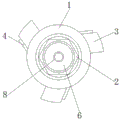
FIG. 3 is a schematic view of the bottom view of the PDC high strength bleeder bit of the present invention.
In the figure: 1. rotating the support; 2. connecting a drill handle; 3. a serrated alloy head; 4. a toothed plate; 5. a groove; 6. connecting columns; 7. a chute; 8. and a liquid spraying through hole.
Detailed Description
In order to make the objects, technical solutions and advantages of the embodiments of the present invention clearer, the technical solutions in the embodiments of the present invention will be clearly and completely described below with reference to the drawings in the embodiments of the present invention, and it is obvious that the described embodiments are some, but not all, embodiments of the present invention. The components of embodiments of the present invention generally described and illustrated in the figures herein may be arranged and designed in a wide variety of different configurations. Thus, the following detailed description of the embodiments of the present invention, presented in the figures, is not intended to limit the scope of the invention, as claimed, but is merely representative of selected embodiments of the invention. All other embodiments, which can be derived by a person skilled in the art from the embodiments given herein without making any creative effort, shall fall within the protection scope of the present invention.
It should be noted that: like reference numbers and letters refer to like items in the following figures, and thus, once an item is defined in one figure, it need not be further defined and explained in subsequent figures.
In the description of the present invention, it should be noted that the terms "center", "upper", "lower", "left", "right", "vertical", "horizontal", "inner", "outer", etc. indicate orientations or positional relationships based on the orientations or positional relationships shown in the drawings or the orientations or positional relationships that the products of the present invention are conventionally placed in use, and are only used for convenience in describing the present invention and simplifying the description, but do not indicate or imply that the devices or elements referred to must have a specific orientation, be constructed and operated in a specific orientation, and thus, should not be construed as limiting the present invention. Furthermore, the terms "first," "second," "third," and the like are used solely to distinguish one from another and are not to be construed as indicating or implying relative importance.
In the embodiment shown in fig. 1-3, the invention provides a PDC high-strength bleed-off drill bit, which comprises a rotating support 1, a connecting drill shank 2, a sawtooth alloy head 3, a toothed plate 4, a groove 5, a connecting column 6, a chute 7 and a liquid spraying through hole 8, wherein one end of the rotating support 1 is provided with the connecting drill shank 2, the connecting drill shank 2 is in a regular hexagonal prism shape, the axial line of the connecting drill shank 2 is coincident with the axial line of the rotating support 1, the connecting drill shank 2 is in a regular hexagonal prism shape, so that when the connecting drill shank 2 is in connecting and clamping, a clamping device is convenient to tightly contact and clamp the connecting drill shank 2, the sawtooth alloy head 3 is welded and fixed at one end of the rotating support 1 far away from the connecting drill shank 2, the sawtooth alloy head 3 is provided with three, and the three sawtooth alloy heads 3 are distributed on the side surface of the rotating support 1 at equal intervals of 120 degrees, and the top of the sawtooth alloy head 3 is sawtooth-shaped, so that the sawtooth alloy head 3 is convenient to drill, wherein,
the toothed plate 4 is arranged on the side surface of the sawtooth alloy head 3, the groove 5 is formed in the side surface of the connecting drill handle 2, the length of the groove 5 is smaller than the width of the connecting drill handle 2, the sectional shape of the groove 5 is semicircular, the axial lead of the groove 5 and the axial lead of the connecting drill handle 2 are vertically distributed, the sectional shape of the groove 5 is semicircular, the connecting drill handle 2 is conveniently and stably connected with a clamping device through the groove 5, the connecting drill handle 2 is locked in an anti-skidding mode through the groove 5 when rotating, a connecting column 6 is arranged at one end, far away from the rotating support 1, of the connecting drill handle 2, a sliding groove 7 is formed in the middle of the outer side of the connecting column 6, the sliding groove 7 is annularly formed in the outer side of the connecting column 6, the sectional shape of the sliding groove 7 is U-shaped, and the sliding groove 7 is clamped with the clamping device, thereby effectively preventing the drill bit from falling off, and the liquid spraying through hole 8 penetrates through the rotating support 1 and is arranged inside the connecting drill handle 2 and the connecting column 6.
The working principle is as follows: when the PDC high-strength discharge drill bit is used, firstly, the connecting column 6 connected with the bottom of the drill handle 2 is inserted into a motor clamping seat matched with the drill bit, and is clamped with corresponding clamping equipment through the chute 7 annularly arranged on the outer side of the connecting column 6, so that the connecting drill handle 2 cannot fall off after being installed, then, the connecting drill handle 2 and the clamping equipment of the regular hexagonal prism are clamped through clamping and fixing the clamping equipment, and are clamped and fixed with the clamping equipment through the groove 5 connected with the outer side surface of the drill handle 2, so that when the rotating motor equipment drives the connecting drill handle 2 to rotate, the connecting drill handle 2 and the clamping equipment cannot slip, when the rotating motor equipment drives the PDC high-strength discharge drill bit to rotate at a high speed, the connecting drill handle 2 drives the sawtooth alloy head 3 on the outer side of the rotating support 1 to drill a rock layer, and the sawtooth alloy head 3 on the top is in the rock layer to drill continuously, and the coolant is sprayed from the top end of the rotary support 1 to the surface of the sawtooth alloy head 3 through a liquid spraying through hole 8 penetrating through the connecting column 6, the connecting drill handle 2 and the rotary support 1, so that the sawtooth alloy head 3 is cooled, and the side surface of the sawtooth alloy head 3 is reinforced by the toothed plate 4, which is not described in detail in this specification and is well known to those skilled in the art.
The above embodiments are only specific examples of the present invention, and the protection scope of the present invention includes but is not limited to the product forms and styles of the above embodiments, and any suitable changes or modifications made by those skilled in the art according to the claims of the present invention shall fall within the protection scope of the present invention.
Claims (5)
- The PDC high-strength discharge drill bit comprises a rotating support (1), a sawtooth alloy head (3) and a liquid spraying through hole (8), and is characterized in that: one end of the rotating support (1) is provided with a connecting drill handle (2), the sawtooth alloy head (3) is welded and fixed at one end of the rotating support (1) far away from the connecting drill handle (2), wherein,the side of sawtooth alloy head (3) is provided with pinion rack (4), side of connecting drillstock (2) is seted up fluted (5), the one end of connecting drillstock (2) and keeping away from rotating support (1) is provided with spliced pole (6), spout (7) have been seted up at the outside middle part of spliced pole (6), hydrojet through-hole (8) run through set up in the inside of rotating support (1), connecting drillstock (2) and spliced pole (6).
- 2. The PDC high strength bleeder drill bit according to claim 1, wherein: the shape of the connecting drill handle (2) is a regular hexagonal prism, and the axis of the connecting drill handle (2) is coincident with the axis of the rotating support (1).
- 3. The PDC high strength bleeder drill bit according to claim 1, wherein: the saw-tooth alloy heads (3) are arranged in three numbers, the three saw-tooth alloy heads (3) are distributed on the side surface of the rotating support (1) at 120 degrees at equal intervals, and the top of each saw-tooth alloy head (3) is in a sawtooth shape.
- 4. The PDC high strength bleeder drill bit according to claim 1, wherein: the length of the groove (5) is smaller than the width of the drill handle (2), the cross section of the groove (5) is semicircular, and the axial lead of the groove (5) and the axial lead of the drill handle (2) are vertically distributed.
- 5. The PDC high strength bleeder drill bit according to claim 1, wherein: the sliding groove (7) is annularly arranged on the outer side of the connecting column (6), and the cross section of the sliding groove (7) is U-shaped.
Priority Applications (1)
| Application Number | Priority Date | Filing Date | Title |
|---|---|---|---|
| CN202010143420.0A CN111236849A (en) | 2020-03-04 | 2020-03-04 | PDC high-strength discharge drill bit |
Applications Claiming Priority (1)
| Application Number | Priority Date | Filing Date | Title |
|---|---|---|---|
| CN202010143420.0A CN111236849A (en) | 2020-03-04 | 2020-03-04 | PDC high-strength discharge drill bit |
Publications (1)
| Publication Number | Publication Date |
|---|---|
| CN111236849A true CN111236849A (en) | 2020-06-05 |
Family
ID=70880179
Family Applications (1)
| Application Number | Title | Priority Date | Filing Date |
|---|---|---|---|
| CN202010143420.0A Pending CN111236849A (en) | 2020-03-04 | 2020-03-04 | PDC high-strength discharge drill bit |
Country Status (1)
| Country | Link |
|---|---|
| CN (1) | CN111236849A (en) |
Citations (9)
| Publication number | Priority date | Publication date | Assignee | Title |
|---|---|---|---|---|
| CN2444740Y (en) * | 2000-05-06 | 2001-08-29 | 宁波保华工业刷有限公司 | Quick assembled drilling bit |
| CN101255796A (en) * | 2007-02-27 | 2008-09-03 | 山特维克知识产权股份有限公司 | Reversible cutting tool with shield |
| CN201110132Y (en) * | 2007-11-17 | 2008-09-03 | 邹城兖矿泰德工贸有限公司 | Extrusion-proof combined reaming bit for mining |
| CN201687393U (en) * | 2010-05-11 | 2010-12-29 | 邹城兖矿泰德工贸有限公司 | Special drill bit for hard rocks |
| CN102528131A (en) * | 2011-12-09 | 2012-07-04 | 浙江野牛工具有限公司 | Shank connecting drill and manufacturing method thereof |
| CN203330467U (en) * | 2013-07-23 | 2013-12-11 | 宁波麦克潘特电动工具有限公司 | Drill bit quick to replace |
| CN206703215U (en) * | 2017-02-27 | 2017-12-05 | 丹阳市博瑞工具有限公司 | A kind of Three-tip woodwork drill |
| CN109441366A (en) * | 2018-12-27 | 2019-03-08 | 河南理工大学 | It is a kind of can bidirectional rotation anchor cable drill-steel set |
| CN110566128A (en) * | 2019-08-22 | 2019-12-13 | 北京东地岩土工程有限公司 | Cobble stratum soil nail drilling equipment |
-
2020
- 2020-03-04 CN CN202010143420.0A patent/CN111236849A/en active Pending
Patent Citations (9)
| Publication number | Priority date | Publication date | Assignee | Title |
|---|---|---|---|---|
| CN2444740Y (en) * | 2000-05-06 | 2001-08-29 | 宁波保华工业刷有限公司 | Quick assembled drilling bit |
| CN101255796A (en) * | 2007-02-27 | 2008-09-03 | 山特维克知识产权股份有限公司 | Reversible cutting tool with shield |
| CN201110132Y (en) * | 2007-11-17 | 2008-09-03 | 邹城兖矿泰德工贸有限公司 | Extrusion-proof combined reaming bit for mining |
| CN201687393U (en) * | 2010-05-11 | 2010-12-29 | 邹城兖矿泰德工贸有限公司 | Special drill bit for hard rocks |
| CN102528131A (en) * | 2011-12-09 | 2012-07-04 | 浙江野牛工具有限公司 | Shank connecting drill and manufacturing method thereof |
| CN203330467U (en) * | 2013-07-23 | 2013-12-11 | 宁波麦克潘特电动工具有限公司 | Drill bit quick to replace |
| CN206703215U (en) * | 2017-02-27 | 2017-12-05 | 丹阳市博瑞工具有限公司 | A kind of Three-tip woodwork drill |
| CN109441366A (en) * | 2018-12-27 | 2019-03-08 | 河南理工大学 | It is a kind of can bidirectional rotation anchor cable drill-steel set |
| CN110566128A (en) * | 2019-08-22 | 2019-12-13 | 北京东地岩土工程有限公司 | Cobble stratum soil nail drilling equipment |
Similar Documents
| Publication | Publication Date | Title |
|---|---|---|
| CN111236849A (en) | PDC high-strength discharge drill bit | |
| CN214993948U (en) | Adjustable rock matter side slope stock reinforcing apparatus | |
| CN213916813U (en) | Welding equipment for metal product production | |
| CN211341869U (en) | Railing is prevented to building engineering instrument formula stair | |
| CN213104683U (en) | Novel twist drill | |
| CN216247317U (en) | Core sampling device for geological exploration | |
| CN213024954U (en) | Teaching display device for software engineering | |
| CN112302539B (en) | Reinforced borer | |
| CN211805780U (en) | Auxiliary positioning device for mounting automobile fastener | |
| CN210264554U (en) | Drilling rig for geological survey | |
| CN210231034U (en) | Cold drawing chuck for seamless steel tube | |
| CN211008451U (en) | Geology reconnaissance probing device | |
| CN215485914U (en) | Horizontal well directional well anti-sticking device | |
| CN213116223U (en) | Core drilling device convenient for taking core | |
| CN206824694U (en) | Aluminium bar drilling machine | |
| CN212079206U (en) | Auxiliary device for underreaming of oil production well in oil field | |
| CN213063473U (en) | Geotechnical engineering reconnaissance is with high efficiency drilling machine | |
| CN216240483U (en) | Oil well logging perforation cable clamping tool | |
| CN203624916U (en) | Well logging pulley | |
| CN214935023U (en) | Pay-off for construction | |
| CN108500351A (en) | Cold spiral bit in a kind of coating | |
| CN112903505B (en) | TBM rock breaking test device | |
| CN216540274U (en) | Material feeding unit is used in steel wire processing | |
| CN220628843U (en) | Mounting bracket | |
| CN211680145U (en) | Drilling tool for building construction |
Legal Events
| Date | Code | Title | Description |
|---|---|---|---|
| PB01 | Publication | ||
| PB01 | Publication | ||
| SE01 | Entry into force of request for substantive examination | ||
| SE01 | Entry into force of request for substantive examination | ||
| RJ01 | Rejection of invention patent application after publication |
Application publication date: 20200605 |
|
| RJ01 | Rejection of invention patent application after publication |