CN111229691A - Cleaning device for removing mud from earthworms - Google Patents
Cleaning device for removing mud from earthworms Download PDFInfo
- Publication number
- CN111229691A CN111229691A CN202010121972.1A CN202010121972A CN111229691A CN 111229691 A CN111229691 A CN 111229691A CN 202010121972 A CN202010121972 A CN 202010121972A CN 111229691 A CN111229691 A CN 111229691A
- Authority
- CN
- China
- Prior art keywords
- rod
- earthworms
- rotating
- belt pulley
- rack
- Prior art date
- Legal status (The legal status is an assumption and is not a legal conclusion. Google has not performed a legal analysis and makes no representation as to the accuracy of the status listed.)
- Granted
Links
Images


Classifications
-
- B—PERFORMING OPERATIONS; TRANSPORTING
- B08—CLEANING
- B08B—CLEANING IN GENERAL; PREVENTION OF FOULING IN GENERAL
- B08B3/00—Cleaning by methods involving the use or presence of liquid or steam
- B08B3/02—Cleaning by the force of jets or sprays
- B08B3/022—Cleaning travelling work
-
- A—HUMAN NECESSITIES
- A01—AGRICULTURE; FORESTRY; ANIMAL HUSBANDRY; HUNTING; TRAPPING; FISHING
- A01K—ANIMAL HUSBANDRY; CARE OF BIRDS, FISHES, INSECTS; FISHING; REARING OR BREEDING ANIMALS, NOT OTHERWISE PROVIDED FOR; NEW BREEDS OF ANIMALS
- A01K67/00—Rearing or breeding animals, not otherwise provided for; New breeds of animals
- A01K67/033—Rearing or breeding invertebrates; New breeds of invertebrates
- A01K67/0332—Earthworms
-
- B—PERFORMING OPERATIONS; TRANSPORTING
- B08—CLEANING
- B08B—CLEANING IN GENERAL; PREVENTION OF FOULING IN GENERAL
- B08B13/00—Accessories or details of general applicability for machines or apparatus for cleaning
-
- B—PERFORMING OPERATIONS; TRANSPORTING
- B08—CLEANING
- B08B—CLEANING IN GENERAL; PREVENTION OF FOULING IN GENERAL
- B08B3/00—Cleaning by methods involving the use or presence of liquid or steam
- B08B3/04—Cleaning involving contact with liquid
- B08B3/10—Cleaning involving contact with liquid with additional treatment of the liquid or of the object being cleaned, e.g. by heat, by electricity or by vibration
Abstract
The invention relates to a cleaning device, in particular to a cleaning device for removing mud of earthworms. The technical problem to be solved is how to provide a cleaning device for removing mud from earthworms, which can automatically and quickly clean the earthworms without damaging the earthworms. A cleaning device for removing mud of earthworms comprises a base, a rack, a driving component, a material storage and water spraying component, a rotating component, a clamping component, a rotating and inclining component and the like; be equipped with the frame that plays supporting role in the base, be equipped with the drive assembly of the power that provides through the motor in the frame, be equipped with in the frame and carry out the earthworm through the mode of opening and shutting and place and carry out the storage water spray assembly that clears up through the washing mode. According to the invention, earthworms are placed and cleaned through the storage water spraying assembly, and meanwhile, the storage water spraying assembly is matched with the rotating assembly and the rotating inclined assembly, so that the earthworms can be rotated when being washed by water, and the earthworms can be cleaned more comprehensively.
Description
Technical Field
The invention relates to a cleaning device, in particular to a cleaning device for removing mud of earthworms.
Background
The earthworms are named as earthworm, ricefield eel and the like, belong to annelids, belong to the animals living in the vegetative and saprophytic life, and are distributed in Asia, south America and the like. The earthworms can be used for preparing medicines, and the earthworms need to be cleaned when the earthworms are used for preparing medicines.
When wasing the earthworm, need place the earthworm in a container, then use water to continuously wash, at the in-process that washes, still need use continuous the earthworm with turning for the earthworm can be by the sanitization, and such mode consumes time long, and earthworm itself is soft, turns over the earthworm and can make it be injured, is unfavorable for the use in later stage.
Therefore, there is a need to develop a cleaning device for removing mud from earthworms, which can automatically and rapidly clean earthworms without damaging the earthworms.
Disclosure of Invention
In order to overcome the defects that the existing earthworm cleaning mode is slow in speed and easy to damage earthworms, the invention has the technical problems that: provided is a cleaning device for removing mud from earthworms, which can automatically and rapidly clean earthworms without damaging the earthworms.
The technical implementation scheme of the invention is as follows: a belt cleaning device that earthworm desliming was used, including: a base; the frame is arranged on the base; the driving assembly is arranged on the rack and provides power through the motor; the storage water spraying assembly is arranged on the rack, and earthworms are placed in an opening and closing mode and cleaned in a water washing mode; the rotating assembly is arranged on the outer side of the rack and is clamped in a lifting mode; screens subassembly is installed on storage water spray subassembly, and the tilt rotation subassembly is installed and is leaned on through the pulling mode, can assist the rotation simultaneously.
Optionally, the driving assembly comprises a speed reduction motor, a first belt pulley, a first rotating rod, a second belt pulley and a first flat belt, the speed reduction motor is installed on the outer side of the rack, the first belt pulley is connected to an output shaft of the speed reduction motor, the first rotating rod is installed on the rack and penetrates through the lower wall of the rack, the second belt pulley is arranged at one end of the first rotating rod, and the first flat belt is wound between the second belt pulley and the first belt pulley.
Optionally, the storage water spray assembly comprises a lower net frame, a vertical rod, a disc, an upper net frame and a water inlet hose, the rotary inclined assembly is provided with the lower net frame, the vertical rod is slidably arranged above the rack, the bottom end of the vertical rod is provided with the disc, the water inlet hose is connected between the disc and the rack, the water inlet hose penetrates through the disc, and the rotary bottom of the disc is provided with the upper net frame.
Optionally, the rotating assembly comprises a third belt pulley, a second rotating rod, a fourth belt pulley, a second flat belt, a circular plate, a lead screw, a nut, a bearing, a first ring and a first connecting rod, the other end of the first rotating rod is connected with the third belt pulley, the second rotating rod is installed in the rack in a rotating mode, the fourth belt pulley is installed on the second rotating rod, the second flat belt is wound between the fourth belt pulley and the third belt pulley, the tail end of the second rotating rod is connected with the lead screw, the circular plate is installed on the rack, the lead screw penetrates through the circular plate, the nut is connected onto the lead screw through threads, the bearing is installed on the outer side of the nut, the first ring is connected to the outer side of the bearing, and the first connecting rod is connected between the first.
Optionally, the screens subassembly is including the wane, first sliding block, U type catch bar, little catch bar, spring and guide bar, install in the frame of lead screw top can wobbling wane, it has two first sliding trays to open on the wane, first sliding tray internal sliding formula is equipped with first sliding block, the rotation type is equipped with U type catch bar on the first sliding block in the outside, it has circular recess to open on the U type catch bar, circular recess in-connection has the spring, spring trailing end connection has little catch bar, the rotation type is connected with the guide bar on the first sliding block of inboard, the guide bar slides and passes the nut.
Optionally, the rotating and tilting assembly comprises a fixing rod, a second ring, arc-shaped sliding blocks, a second connecting rod, a pull wire and a diamond-shaped block, the fixing rod is installed on the outer side of the rack, the second ring is rotatably arranged on the fixing rod, an annular sliding groove is formed in the second ring, at least two arc-shaped sliding blocks are arranged in the annular sliding groove in a sliding mode, the second connecting rod is connected between the arc-shaped sliding blocks and the lower net frame, the diamond-shaped block is installed on the first rotating rod, a diamond-shaped hole is formed in the center of the outer side of the lower net frame, the pull wire is connected between the vertical rod and the second ring, and the pull wire.
Optionally, still including second sliding block and arc otter board, the symmetry is opened on the lower screen frame has the second sliding tray, and all slidingtype are equipped with the second sliding block in the second sliding tray, are connected with the arc otter board between the second sliding block.
Optionally, the screen frame further comprises square blocks, a cross rod and a third ring, wherein the second ring is provided with at least two square blocks, the inner sides of the square blocks are provided with the cross rod, the lower screen frame is provided with the third ring, the third ring is provided with at least two arc-shaped grooves, and the arc-shaped grooves are matched with the cross rod.
The invention has the following advantages: according to the invention, earthworms are placed and cleaned through the storage water spraying assembly, and meanwhile, the storage water spraying assembly is matched with the rotating assembly and the rotating inclined assembly, so that the earthworms can be rotated when the earthworms are washed by water, the earthworms can be cleaned more comprehensively, meanwhile, the lower net frame is inclined, the cleaned earthworms can be taken out conveniently, the lower net frame can shake when rotating, the earthworms in the lower net frame can be cleaned better, and meanwhile, the earthworms cannot be damaged.
Drawings
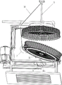
Fig. 1 is a schematic perspective view of a first embodiment of the present invention.
Fig. 2 is a schematic perspective view of the present invention a.
Fig. 3 is a schematic perspective view of the present invention B.
Fig. 4 is a schematic perspective view of the present invention C.
Fig. 5 is a partial perspective view of the present invention.
Fig. 6 is a schematic perspective view of the present invention D.
Fig. 7 is a schematic perspective view of a second embodiment of the present invention.
Fig. 8 is a schematic perspective view of the invention E.
Fig. 9 is a schematic perspective view of the present invention F.
In the above drawings: 1: base, 2: frame, 3: gear motor, 4: first pulley, 5: first rotating shaft, 6: second pulley, 7: first flat belt, 8: lower screen frame, 9: vertical bar, 10: disc, 11: upper screen frame, 12: water inlet hose, 13: third pulley, 14: second rotating rod, 15: fourth pulley, 16: second flat belt, 17: circular plate, 18: screw rod, 19: nut, 20: bearing, 21: first ring, 22: first connecting rod, 23: rocker, 24: first slide groove, 25: first slider, 26: u-shaped catch bar, 27: circular groove, 28: small push rod, 201: spring, 29: guide bar, 30: fixing rod, 31: second ring, 32: annular slide groove, 33: arc-shaped sliding block, 34: second connecting rod, 35: diamond holes, 36: stay wire, 301: diamond, 37: second slide groove, 38: second slider, 39: arc net plate, 40: square block, 41: cross bar, 42: third ring, 43: an arc-shaped groove.
Detailed Description
Reference herein to an embodiment means that a particular feature, structure, or characteristic described in connection with the embodiment can be included in at least one embodiment of the invention. The appearances of the phrase in various places in the specification are not necessarily all referring to the same embodiment, nor are separate or alternative embodiments mutually exclusive of other embodiments. It is explicitly and implicitly understood by one skilled in the art that the embodiments described herein can be combined with other embodiments.
Example 1
The utility model provides a belt cleaning device that earthworm removed mud usefulness, as shown in fig. 1-7, including base 1, frame 2, drive assembly, storage water spray assembly, runner assembly, screens subassembly and tilt rotation subassembly, be equipped with the frame 2 that plays the supporting role on base 1, 2 right sides in the frame are equipped with the drive assembly through the power that the motor provided, 2 left parts in the frame are equipped with the storage water spray assembly who carries out the earthworm through the mode of opening and shutting and place and clear up through the washing mode, be equipped with the runner assembly who carries out power transmission through the runner assembly on the frame 2 of flushing assembly below, 2 outsides in the frame are equipped with the screens subassembly that carries out the screens through the lift mode, be equipped with on the storage water spray assembly and incline through the pulling mode, simultaneously can assist pivoted tilt rotation subassembly.
As shown in fig. 1, the driving assembly comprises a speed reduction motor 3, a first belt pulley 4, a first rotating rod 5, a second belt pulley 6 and a first flat belt 7, the speed reduction motor 3 is installed on the right side of the rack 2 through a bolt, the first belt pulley 4 is connected to an output shaft of the speed reduction motor 3, the first rotating rod 5 is installed in the middle of the lower portion of the rack 2 in a rotating mode, the first rotating rod 5 penetrates through the lower wall of the rack 2, the second belt pulley 6 is arranged at the bottom end of the first rotating rod 5, and the first flat belt 7 is wound between the second belt pulley 6 and the first belt pulley 4.
As shown in fig. 1, the storage water spray assembly comprises a lower net frame 8, a vertical rod 9, a disc 10, an upper net frame 11 and a water inlet hose 12, the lower net frame 8 is arranged on the rotary inclined assembly, the vertical rod 9 which slides up and down is arranged above the rack 2, the disc 10 is arranged at the bottom end of the vertical rod 9, the water inlet hose 12 is connected between the disc 10 and the rack 2, the water inlet hose 12 has elasticity, the water inlet hose 12 penetrates through the disc 10, and the upper net frame 11 is rotatably arranged at the bottom of the disc 10.
As shown in fig. 1 and 2, the rotating assembly includes a third pulley 13, a second rotating rod 14, a fourth pulley 15, a second flat belt 16, a circular plate 17, the lead screw 18, the nut 19, a bearing 20, first ring 21 and head rod 22, the top of first bull stick 5 is connected with third belt pulley 13, second bull stick 14 is installed to the right side rotary type in the frame 2, install fourth belt pulley 15 on the second bull stick 14, around having the flat belt 16 of second between fourth belt pulley 15 and the third belt pulley 13, second bull stick 14 top is connected with lead screw 18, circular slab 17 is installed to 2 right side lower positions of frame, lead screw 18 runs through circular slab 17, there is nut 19 on the lead screw 18 through threaded connection, bearing 20 is installed in the nut 19 outside, nut 19 and bearing 20 interference connection, the bearing 20 outside is connected with first ring 21, be connected with head rod 22 between first ring 21 and the disc 10.
As shown in fig. 3, 4 and 5, the screens subassembly is including wane 23, first sliding block 25, U type catch bar 26, little catch bar 28, spring 201 and guide bar 29, but the wobbling 23 that can swing is installed on frame 2 top right side, first sliding tray 24 has all been opened to wane 23 bottom left and right sides, first sliding tray 24 internal sliding formula is equipped with first sliding block 25, the first sliding block 25 in the outside is the commentaries on classics formula and is equipped with U type catch bar 26, it has circular recess 27 to open on the U type catch bar 26, circular recess 27 internal connection has spring 201, spring 201 top is connected with little catch bar 28, the commentaries on classics formula is connected with guide bar 29 on the first sliding block 25 on the left side, nut 19 one side is opened has the through-hole, guide bar 29 passes the through-hole on nut 19, little catch bar 28 sets up with the through-hole on the.
As shown in fig. 6 and 7, the rotating and tilting assembly comprises a fixing rod 30, a second ring 31, an arc-shaped sliding block 33, a second connecting rod 34, a pull wire 36 and a diamond-shaped block 301, the fixing rod 30 is installed on the lower portion of the left side of the rack 2, the second ring 31 is rotatably installed at the top end of the fixing rod 30, an annular sliding groove 32 is formed in the top of the second ring 31, four arc-shaped sliding blocks 33 are slidably arranged in the annular sliding groove 32, the second connecting rod 34 is welded between the arc-shaped sliding blocks 33 and the lower rack 8, the diamond-shaped block 301 is installed at the top end of the first rotating rod 5, a diamond-shaped hole 35 is formed in the center of the outer side of the lower rack 8, the pull wire 36 is connected between the upper portion of the vertical rod 9.
The working principle of the above embodiment is as follows: when the device is needed to clean earthworms, the earthworms are firstly placed into the storage water spraying assembly, then the storage water spraying assembly is driven to close through the driving assembly, after the storage water spraying assembly closes, the clamping assembly keeps the position of the storage water spraying assembly, meanwhile, the rotating assembly and the rotating and inclining assembly drive the storage water spraying assembly to rotate, the earthworms are cleaned in the storage water spraying assembly, after the earthworms are cleaned, the rotating assembly is loosened through the clamping assembly and triggered, the storage water spraying assembly is driven to be opened, the storage water spraying assembly is inclined through the rotating and inclining assembly, and then the cleaned earthworms can be taken out.
When needs rotate clearance earthworm to storage water spray component, at first control gear motor 3 rotates, drives first bull stick 5 through first belt pulley 4, second belt pulley 6 and first flat belt 7 and rotates to drive storage water spray component and rotate and wash the earthworm, the earthworm washs and finishes, and storage water spray component opens the slope after, control gear motor 3 stop work.
When cleaning the earthworm, pour the earthworm into lower screen frame 8 in, drive assembly control runner assembly after that and drive upper screen frame 11 downstream, lower screen frame 8 that drives the slope through rotating the slope subassembly simultaneously becomes the horizontality, upper screen frame 11 closes with lower screen frame 8 this moment, the screens subassembly will keep upper screen frame 11 with the position of lower screen frame 8, drive lower screen frame 8 and upper screen frame 11 rotation through runner assembly after that, put through water hose 12 and water source simultaneously, the water sprays on the earthworm, wash the earthworm, after the earthworm washs finishing, drive upper screen frame 11 rebound through drive assembly and leave lower screen frame 8, make lower screen frame 8 incline to the left through rotating the slope subassembly simultaneously, then control gear motor 3 stop work afterwards, then take out the earthworm that finishes washing.
When the first rotating rod 5 rotates, the third belt pulley 13 is driven to rotate, the fourth belt pulley 15 is driven to rotate through the second flat belt 16, and then the second rotating rod 14 is driven to rotate, so that the screw rod 18 is driven to rotate, the nut 19 and the upper device thereof move downwards, the disc 10 and the upper device thereof are driven to move downwards through the first connecting rod 22, so that the upper screen frame 11 moves downwards, when the upper screen frame 11 moves downwards to be closed with the lower screen frame 8, the nut 19 is loosened by the clamping component, so that the nut 19 rotates and cannot move downwards any more, when the upper screen frame 11 needs to move upwards, the speed reduction motor 3 is controlled to rotate reversely, the screw rod 18 is driven to rotate reversely, at the moment, the nut 19 is fixed by the clamping component, so that the nut 19 does not rotate any more, at the screw rod 18 can drive the nut 19 and the upper device thereof to move upwards to reset, and then the speed reduction motor 3 is.
When the nut 19 and the upper device move downwards to be in contact with the U-shaped push rod 26, the nut is pushed to move downwards, the guide rod 29 is driven to move upwards through the tilting plate 23, after the nut 19 is not clamped by the guide rod 29 any more, the upper screen frame 11 moves downwards to be closed with the lower screen frame 8 at the moment, the nut 19 rotates along with the screw rod 18 at the moment, so that the upper screen frame 11 does not move downwards any more, after the earthworms are cleaned, the speed reducing motor 3 is controlled to rotate reversely, the guide rod 29 is pressed downwards at the moment, the guide rod 29 moves downwards to clamp the nut 19 again, at the moment, because of the small push rod 28 and the spring 201, when the guide rod 29 moves downwards, the U-shaped push rod 26 moves upwards, the spring 201 is compressed, the small push rod 28 enters the circular groove 27 of the U-shaped push rod 26, so that the guide rod 29 can move downwards to fix the nut 19, after the nut 19 moves upwards for a certain distance, will slowly get away from the small pushing rod 28, at this time, the spring 201 will reset, and will drive the small pushing rod 28 to reset upwards.
Go up the frame 11 downstream and drive montant 9 downstream at last, make 36 downstream act as go-between, under 36's effect, lower frame 8 slowly becomes the horizontality, diamond-shaped block 301 card is in diamond 35, frame 8 rotates under first bull stick 5 can drive this moment, wash the earthworm, after the earthworm washs finishing, go up frame 11 upstream and drive 36 upstream acts as go-between, 36 upstream acts as go-between and upwards pulls up second ring 31, make lower frame 8 slope, diamond-shaped block 301 breaks away from diamond 35 simultaneously, lower frame 8 stall. The lower net frame 8 is inclined, so that cleaned earthworms can be taken out conveniently.
Example 2
In addition to embodiment 1, as shown in fig. 8, in order to better take out cleaned earthworms, the earthworm taking-out device further includes a second sliding block 38 and an arc-shaped net plate 39, wherein the left part of the lower net frame 8 is symmetrically provided with a second sliding groove 37 in front and back, the second sliding groove 37 is internally provided with the second sliding block 38 in a sliding manner, and the arc-shaped net plate 39 is connected between the second sliding blocks 38.
As shown in fig. 9, for better cleaning earthworms, the cleaning device further comprises two square blocks 40, a cross bar 41 and a third circular ring 42, the two square blocks 40 are symmetrically arranged at the bottom of the second circular ring 31, the cross bar 41 is arranged on the inner sides of the square blocks 40, the third circular ring 42 is arranged on the lower net frame 8, a circle of arc-shaped groove 43 is formed in the third circular ring 42, and the arc-shaped groove 43 is matched with the cross bar 41.
The working principle of the above embodiment is as follows: when the earthworms need to be taken out, the arc-shaped net plate 39 is upwards pulled out, so that the earthworms can flow out from the notch, the earthworms can be quickly cleaned, and the arc-shaped net plate 39 is reset after the earthworms are cleaned.
In the process of rotating the lower net frame 8, the third ring 42 is driven to rotate, and the lower net frame 8 can shake through the matching of the cross rod 41 and the arc-shaped groove 43, so that earthworms in the lower net frame 8 can be better cleaned.
The above-mentioned embodiments are merely preferred embodiments of the present invention, which are not intended to limit the scope of the present invention, and therefore, all equivalent changes made by the contents of the claims of the present invention should be included in the claims of the present invention.
Claims (8)
1. The utility model provides a belt cleaning device that earthworm desliming was used which characterized by including:
a base;
the frame is arranged on the base;
the driving assembly is arranged on the rack and provides power through the motor;
the storage water spraying assembly is arranged on the rack, and earthworms are placed in an opening and closing mode and cleaned in a water washing mode;
the rotating assembly is arranged on the outer side of the rack and is clamped in a lifting mode;
a clamping component which is arranged on the material storage water spraying component,
the rotating and inclining assembly is installed to incline in a pulling mode and can assist in rotating.
2. The cleaning device for desliming earthworms according to claim 1, which is characterized in that: the driving assembly comprises a speed reducing motor, a first belt pulley, a first rotating rod, a second belt pulley and a first flat belt, the speed reducing motor is installed on the outer side of the rack, the first belt pulley is connected to an output shaft of the speed reducing motor, the first rotating rod is installed on the rack and penetrates through the lower wall of the rack, the second belt pulley is arranged at one end of the first rotating rod, and the first flat belt is wound between the second belt pulley and the first belt pulley.
3. The cleaning device for desliming earthworms according to claim 2, which is characterized in that: the storage water spray assembly comprises a lower net frame, a vertical rod, a disc, an upper net frame and a water inlet hose, the lower net frame is arranged on the rotating inclined assembly, the vertical rod is arranged on the rack in a sliding mode, the disc is arranged at the bottom end of the vertical rod, the water inlet hose is connected between the disc and the rack, the water inlet hose penetrates through the disc, and the upper net frame is arranged on the bottom rotary mode of the disc.
4. The cleaning device for desliming earthworms according to claim 3, which is characterized in that: the rotating assembly comprises a third belt pulley, a second rotating rod, a fourth belt pulley, a second flat belt, a circular plate, a screw rod, a nut, a bearing, a first circular ring and a first connecting rod, the other end of the first rotating rod is connected with the third belt pulley, the second rotating rod is installed in the rack in a rotary mode, the fourth belt pulley is installed on the second rotating rod, the second flat belt is wound between the fourth belt pulley and the third belt pulley, the tail end of the second rotating rod is connected with the screw rod, the circular plate is installed on the rack, the screw rod penetrates through the circular plate, the nut is connected onto the screw rod through threads, the bearing is installed on the outer side of the nut, the outer side of the bearing is connected with the first circular ring, and the first connecting rod is connected between.
5. The cleaning device for desliming earthworms according to claim 4, which is characterized in that: screens subassembly is including the wane, first sliding block, U type catch bar, little catch bar, spring and guide bar, install in the frame of lead screw top can wobbling wane, it has two first sliding trays to open on the wane, first sliding tray internal sliding formula is equipped with first sliding block, the rotation type is equipped with U type catch bar on the first sliding block in the outside, it has circular recess to open on the U type catch bar, circular recess in-connection has the spring, spring trailing end connection has little catch bar, the rotation type is connected with the guide bar on the first sliding block of inboard, the guide bar slides and passes the nut.
6. The cleaning device for desliming earthworms according to claim 5, which is characterized in that: the rotating inclined assembly comprises a fixed rod, a second ring, arc-shaped sliding blocks, a second connecting rod, pull wires and a diamond-shaped block, the fixed rod is installed on the outer side of the rack, the second ring is arranged on the fixed rod in a rotating mode, an annular sliding groove is formed in the second ring, at least two arc-shaped sliding blocks are arranged in the annular sliding groove in a sliding mode, the second connecting rod is connected between the arc-shaped sliding blocks and the lower net frame, the diamond-shaped block is installed on the first rotating rod, a diamond-shaped hole is formed in the center of the outer side of the lower net frame, the pull wires are connected between the vertical rods and the second ring, and the pull.
7. The cleaning device for desliming earthworms according to claim 6, which is characterized in that: still including second sliding block and arc otter board, the symmetry is opened on the lower screen frame has the second sliding tray, and the equal slidingtype is equipped with the second sliding block in the second sliding tray, is connected with the arc otter board between the second sliding block.
8. The cleaning device for desliming earthworms according to claim 7, which is characterized in that: the screen frame is characterized by further comprising square blocks, a cross rod and a third ring, wherein at least two square blocks are arranged on the second ring, the cross rod is arranged on the inner side of each square block, the third ring is arranged on the lower screen frame, at least two arc-shaped grooves are formed in the third ring, and the arc-shaped grooves are matched with the cross rod.
Priority Applications (1)
| Application Number | Priority Date | Filing Date | Title |
|---|---|---|---|
| CN202010121972.1A CN111229691B (en) | 2020-02-27 | 2020-02-27 | Cleaning device for removing mud from earthworms |
Applications Claiming Priority (1)
| Application Number | Priority Date | Filing Date | Title |
|---|---|---|---|
| CN202010121972.1A CN111229691B (en) | 2020-02-27 | 2020-02-27 | Cleaning device for removing mud from earthworms |
Publications (2)
| Publication Number | Publication Date |
|---|---|
| CN111229691A true CN111229691A (en) | 2020-06-05 |
| CN111229691B CN111229691B (en) | 2022-07-01 |
Family
ID=70867169
Family Applications (1)
| Application Number | Title | Priority Date | Filing Date |
|---|---|---|---|
| CN202010121972.1A Active CN111229691B (en) | 2020-02-27 | 2020-02-27 | Cleaning device for removing mud from earthworms |
Country Status (1)
| Country | Link |
|---|---|
| CN (1) | CN111229691B (en) |
Cited By (1)
| Publication number | Priority date | Publication date | Assignee | Title |
|---|---|---|---|---|
| CN111957658A (en) * | 2020-07-20 | 2020-11-20 | 陈实 | Cinnabar elutriation device |
Citations (5)
| Publication number | Priority date | Publication date | Assignee | Title |
|---|---|---|---|---|
| KR101676283B1 (en) * | 2015-06-19 | 2016-11-15 | (주)지금강이엔지 | cleaning robot for ceiling air conditioning |
| CN107150050A (en) * | 2017-07-12 | 2017-09-12 | 王亚超 | A kind of cleaning machinery for being used to clean celestial grass |
| CN108405454A (en) * | 2018-04-18 | 2018-08-17 | 江苏安禧生物科技有限公司 | A kind of earthworm processing cleaning device |
| CN110280530A (en) * | 2019-08-05 | 2019-09-27 | 东北电力大学 | A kind of makeup of medical instrument cleaning and sterilizing drying integrated is set |
| CN210080237U (en) * | 2019-05-28 | 2020-02-18 | 嘉兴远信五金科技股份有限公司 | Nut self-cleaning equipment |
-
2020
- 2020-02-27 CN CN202010121972.1A patent/CN111229691B/en active Active
Patent Citations (5)
| Publication number | Priority date | Publication date | Assignee | Title |
|---|---|---|---|---|
| KR101676283B1 (en) * | 2015-06-19 | 2016-11-15 | (주)지금강이엔지 | cleaning robot for ceiling air conditioning |
| CN107150050A (en) * | 2017-07-12 | 2017-09-12 | 王亚超 | A kind of cleaning machinery for being used to clean celestial grass |
| CN108405454A (en) * | 2018-04-18 | 2018-08-17 | 江苏安禧生物科技有限公司 | A kind of earthworm processing cleaning device |
| CN210080237U (en) * | 2019-05-28 | 2020-02-18 | 嘉兴远信五金科技股份有限公司 | Nut self-cleaning equipment |
| CN110280530A (en) * | 2019-08-05 | 2019-09-27 | 东北电力大学 | A kind of makeup of medical instrument cleaning and sterilizing drying integrated is set |
Cited By (1)
| Publication number | Priority date | Publication date | Assignee | Title |
|---|---|---|---|---|
| CN111957658A (en) * | 2020-07-20 | 2020-11-20 | 陈实 | Cinnabar elutriation device |
Also Published As
| Publication number | Publication date |
|---|---|
| CN111229691B (en) | 2022-07-01 |
Similar Documents
| Publication | Publication Date | Title |
|---|---|---|
| CN207026043U (en) | A kind of animal husbandry collecting vessel cleaning device | |
| CN108371841B (en) | Industrial cooling water mud and sand discharging water-saving device | |
| CN111229691B (en) | Cleaning device for removing mud from earthworms | |
| CN205701674U (en) | A kind of instrument high-efficiency washing device for building | |
| CN109222146B (en) | Peanut cleaner | |
| CN207371215U (en) | A kind of air-conditioning filter net cleaning device | |
| CN107997195B (en) | Automatic rhizome peeling and cleaning device and using method thereof | |
| CN108797264B (en) | Antiskid plate collecting device for construction site | |
| CN112379065B (en) | Heavy metal water quality automatic monitoring system | |
| CN114795020A (en) | Efficient automatic cleaning device for glass building curtain wall and using method thereof | |
| CN108487194A (en) | A kind of hydraulic engineering trash rack cleaning equipment | |
| CN110038839A (en) | LED light automatic cleaning system | |
| CN209089977U (en) | A kind of vegetable cleaning device | |
| CN207371216U (en) | A kind of air-conditioning filter net cleaning device of automatic lifting | |
| CN220255359U (en) | Pig house washing unit is used in live pig plant | |
| KR101809413B1 (en) | Dehydration device of vegetables | |
| CN113457762B (en) | Experiment table convenient for experiment in school laboratory | |
| CN219894330U (en) | Squid fishing machine net bracket with safe reason line function | |
| CN219651150U (en) | New energy automobile chassis device | |
| CN116174392B (en) | Oil immersion type cleaning machine for surface treatment of prestressed anchor backing plate | |
| CN220167125U (en) | Pipeline cleaning device for road engineering road drainage | |
| CN219556236U (en) | Stone removing device for fruit and vegetable processing | |
| CN209950258U (en) | Be used for abluent basin of birds meat | |
| CN219502089U (en) | Wash filter component | |
| CN113663304B (en) | Sports goods cleaning device for sports |
Legal Events
| Date | Code | Title | Description |
|---|---|---|---|
| PB01 | Publication | ||
| PB01 | Publication | ||
| SE01 | Entry into force of request for substantive examination | ||
| SE01 | Entry into force of request for substantive examination | ||
| GR01 | Patent grant | ||
| GR01 | Patent grant | ||
| TR01 | Transfer of patent right |
Effective date of registration: 20230424 Address after: 301509 Zhouying, Caozhuang Village, Lutai Town, Ninghe District, Tianjin City Patentee after: TIANJIN JIALIMING BIOLOGICAL TECHNOLOGY CO.,LTD. Address before: Room 1206, Chuangye building, No. 18, Gaoxin Second Road, Nanchang high tech Industrial Development Zone, Nanchang, Jiangxi 330093 Patentee before: Cao Yunfa |
|
| TR01 | Transfer of patent right |