CN111221069B - Backlight module and light guide plate thereof and display device using backlight module - Google Patents
Backlight module and light guide plate thereof and display device using backlight module Download PDFInfo
- Publication number
- CN111221069B CN111221069B CN201811407203.7A CN201811407203A CN111221069B CN 111221069 B CN111221069 B CN 111221069B CN 201811407203 A CN201811407203 A CN 201811407203A CN 111221069 B CN111221069 B CN 111221069B
- Authority
- CN
- China
- Prior art keywords
- light
- angle
- guide plate
- light guide
- luminance
- Prior art date
- Legal status (The legal status is an assumption and is not a legal conclusion. Google has not performed a legal analysis and makes no representation as to the accuracy of the status listed.)
- Active
Links
Images


Classifications
-
- G—PHYSICS
- G02—OPTICS
- G02B—OPTICAL ELEMENTS, SYSTEMS OR APPARATUS
- G02B6/00—Light guides; Structural details of arrangements comprising light guides and other optical elements, e.g. couplings
- G02B6/0001—Light guides; Structural details of arrangements comprising light guides and other optical elements, e.g. couplings specially adapted for lighting devices or systems
- G02B6/0011—Light guides; Structural details of arrangements comprising light guides and other optical elements, e.g. couplings specially adapted for lighting devices or systems the light guides being planar or of plate-like form
- G02B6/0033—Means for improving the coupling-out of light from the light guide
- G02B6/005—Means for improving the coupling-out of light from the light guide provided by one optical element, or plurality thereof, placed on the light output side of the light guide
- G02B6/0053—Prismatic sheet or layer; Brightness enhancement element, sheet or layer
-
- G—PHYSICS
- G02—OPTICS
- G02B—OPTICAL ELEMENTS, SYSTEMS OR APPARATUS
- G02B6/00—Light guides; Structural details of arrangements comprising light guides and other optical elements, e.g. couplings
- G02B6/0001—Light guides; Structural details of arrangements comprising light guides and other optical elements, e.g. couplings specially adapted for lighting devices or systems
- G02B6/0011—Light guides; Structural details of arrangements comprising light guides and other optical elements, e.g. couplings specially adapted for lighting devices or systems the light guides being planar or of plate-like form
- G02B6/0033—Means for improving the coupling-out of light from the light guide
- G02B6/0035—Means for improving the coupling-out of light from the light guide provided on the surface of the light guide or in the bulk of it
- G02B6/0038—Linear indentations or grooves, e.g. arc-shaped grooves or meandering grooves, extending over the full length or width of the light guide
-
- G—PHYSICS
- G02—OPTICS
- G02B—OPTICAL ELEMENTS, SYSTEMS OR APPARATUS
- G02B6/00—Light guides; Structural details of arrangements comprising light guides and other optical elements, e.g. couplings
- G02B6/0001—Light guides; Structural details of arrangements comprising light guides and other optical elements, e.g. couplings specially adapted for lighting devices or systems
- G02B6/0011—Light guides; Structural details of arrangements comprising light guides and other optical elements, e.g. couplings specially adapted for lighting devices or systems the light guides being planar or of plate-like form
- G02B6/0033—Means for improving the coupling-out of light from the light guide
- G02B6/0035—Means for improving the coupling-out of light from the light guide provided on the surface of the light guide or in the bulk of it
- G02B6/004—Scattering dots or dot-like elements, e.g. microbeads, scattering particles, nanoparticles
- G02B6/0043—Scattering dots or dot-like elements, e.g. microbeads, scattering particles, nanoparticles provided on the surface of the light guide
-
- G—PHYSICS
- G02—OPTICS
- G02B—OPTICAL ELEMENTS, SYSTEMS OR APPARATUS
- G02B6/00—Light guides; Structural details of arrangements comprising light guides and other optical elements, e.g. couplings
- G02B6/0001—Light guides; Structural details of arrangements comprising light guides and other optical elements, e.g. couplings specially adapted for lighting devices or systems
- G02B6/0011—Light guides; Structural details of arrangements comprising light guides and other optical elements, e.g. couplings specially adapted for lighting devices or systems the light guides being planar or of plate-like form
- G02B6/0033—Means for improving the coupling-out of light from the light guide
- G02B6/005—Means for improving the coupling-out of light from the light guide provided by one optical element, or plurality thereof, placed on the light output side of the light guide
-
- G—PHYSICS
- G09—EDUCATION; CRYPTOGRAPHY; DISPLAY; ADVERTISING; SEALS
- G09F—DISPLAYING; ADVERTISING; SIGNS; LABELS OR NAME-PLATES; SEALS
- G09F9/00—Indicating arrangements for variable information in which the information is built-up on a support by selection or combination of individual elements
Abstract
A backlight module comprises a light guide plate having an upper surface, a lower surface and a light modulation structure on the lower surface; an optical sheet disposed opposite to the upper surface of the light guide plate; and a light source disposed adjacent to the light guide plate, wherein light emitted from the light source has a first brightness distribution in a first direction after passing through the light guide plate, the first brightness distribution has a first maximum brightness and a second maximum brightness, the first maximum brightness corresponds to a first angle, the second maximum brightness corresponds to a second angle, an absolute value of an angle of the first angle and an absolute value of an angle of the second angle are respectively greater than 60 degrees, and an absolute value of a difference between the first maximum brightness and the second maximum brightness is less than or equal to 30% of the first maximum brightness.
Description
Technical Field
The present disclosure relates to a backlight module, a light guide plate thereof and a display device using the same, and more particularly, to a backlight module capable of controlling a light emitting angle, a light guide plate thereof and a display device using the same.
Background
Electronic products with display devices are indispensable to modern people, whether in work, study or leisure and recreation. From personal 3C, such as smart phones, tablet computers, and notebook computers, to large and small products, such as televisions, electronic signs, and even vehicle-mounted display devices, many related products are pervasive in every day part. Consumers also have different pursuits and expectations regarding the electronic characteristics of different electronic products depending on their product purposes.
For example, for a display device that needs to have sufficient brightness to clearly display an image and a peep-proof function, it is important to achieve a good collimation function by concentrating light rays of a display screen in a viewing area of an observer. The traditional light guide plate forms mist dots (the dots contain particles, for example) in order to make the light uniformly emit light (i.e. emit light isotropically in all directions) when the light hits the dots, so that the light emitting angle cannot be adjusted to make the light source concentrated. In addition, other known light guide plates capable of adjusting the light-emitting angle are generally manufactured by injection molding, and an expensive mold is required to form a precise patterning structure on the light guide plate, so that it is difficult to achieve collimating light in applications of medium-sized and large-sized backlight modules, regardless of technical considerations or cost considerations.
Disclosure of Invention
The application relates to a backlight module, a light guide plate thereof and a display device using the same, which controls a light-emitting angle by utilizing a light-adjusting structure of the light guide plate.
According to the present application, a backlight module is provided, which includes a light guide plate having an upper surface, a lower surface and a light adjusting structure located on the lower surface; an optical sheet disposed opposite to the upper surface of the light guide plate; and a light source disposed adjacent to the light guide plate, wherein light emitted from the light source has a first brightness distribution in a first direction after passing through the light guide plate, the first brightness distribution has a first maximum brightness and a second maximum brightness, the first maximum brightness corresponds to a first angle, the second maximum brightness corresponds to a second angle, an absolute value of the angle of the first angle and an absolute value of the angle of the second angle are respectively greater than 60 degrees, and an absolute value of a difference between the first maximum brightness and the second maximum brightness is less than or equal to 30% of the first maximum brightness.
According to the present application, a light guide plate is provided, which includes an upper surface, a lower surface and a light adjusting structure located on the lower surface; when light passes through the light guide plate, a first brightness distribution is formed in a first direction, the first brightness distribution has a first maximum brightness and a second maximum brightness, the first maximum brightness corresponds to a first angle, the second maximum brightness corresponds to a second angle, an angle absolute value of the first angle and an angle absolute value of the second angle are respectively greater than 60 degrees, and an absolute value of a difference between the first maximum brightness and the second maximum brightness is less than or equal to 30% (≦ 30%) of the first maximum brightness.
According to the present application, a display device is provided, which includes a display panel and the backlight module as described above for providing light to the display panel.
Drawings
In order to make the aforementioned objects, features and advantages of the present invention comprehensible, embodiments accompanied with figures are described in detail below, wherein:
fig. 1A is a schematic perspective view of a backlight module according to an embodiment of the present application.
Fig. 1B is a schematic perspective view of a backlight module according to another embodiment of the present application.
Fig. 2A is a schematic cross-sectional view of a light source and a light guide plate according to an embodiment of the present application.
Fig. 2B is a top view of a light source and a light guide plate according to an embodiment of the disclosure.
FIG. 2C is a simplified diagram of light exiting at a low horizontal included angle after the light from the light source of FIG. 2A passes through the light guide plate.
Fig. 3 is a cone polarization diagram measured by a cone polarizer at an approximate center of a light guide plate after light passes through the light guide plate according to an embodiment of the present disclosure.
Fig. 4 is a graph of a first luminance distribution of light emitted from a light source in a first direction after the light passes through a light guide plate according to an embodiment of the present disclosure.
Fig. 5 is a schematic cross-sectional view illustrating an optical sheet in a backlight module according to an embodiment of the present application.
Fig. 6 is a graph of one of second luminance distributions in a first direction and a graph of one of third luminance distributions in a second direction after light emitted from a light source passes through a light guide plate and an optical sheet according to an example of the present application.
Fig. 7A is a conoscopic polarization diagram measured by a conoscope after light passes through the light guide plate and the optical sheet according to an embodiment of the present disclosure.
Fig. 7B is a diagram illustrating a simulation result of luminance distribution of light emitted from a light source after passing through a light guide plate, an optical sheet, and a display panel.
Fig. 8A is a graph of a first luminance distribution in a first direction after light emitted from a light source passes through a light guide plate in several sets of experiments.
Fig. 8B is a graph of a third luminance distribution in the second direction after light emitted from the light source passes through the light guide plate and the optical sheet in several sets of experiments.
FIG. 9 is a schematic cross-sectional view of a light guide plate according to another embodiment of the present application.
Element numbering in the figures:
1: backlight module
11. 11': light guide plate
11a, 11' a: the upper surface of the light guide plate
11 b: lower surface of the light guide plate
11c side surface
110: light incident surface
112: light modulation structure
114: lens and lens assembly
11M: main part
11Ma: upper surface of the main portion
13: optical sheet
13 a: first surface
134: prism
N: normal direction
θ、θ1、θ2: included angle

30: reflecting side sticker
B1, B2: first maximum brightness, second maximum brightness
B3, B4: brightness value
θ11: first angle
θ12: second angle
A1: first visual angle region
A2: second visual angle region
Ac: area of contact
HA、hL、HT: height
DA: maximum width
WT: width of
PL、PT: set the pitch
D1: a first direction
D2: second direction
D3: third direction
C1, C2, E1, E2: curve line
ND: normal direction of light incident surface
OL: light emitting light
HW: half luminance width
Detailed Description
The embodiment of the application provides a backlight module, a light guide plate thereof and a display device using the same, wherein the light guide plate with a dimming structure is provided, so that light rays passing through the light guide plate have a large light-emitting angle. The light guide plate of one application embodiment can be properly matched with an optical sheet, such as a reverse prism sheet, and then a backlight module with collimated light can be provided. The backlight module of the embodiment can be applied to display devices of various types, wherein the applied display devices comprise a display panel and the backlight module of the embodiment which can provide light rays of the display panel. The present application is not limited to the type of the display device. In an application example, the backlight module can provide the maximum brightness when the display device of the backlight module of the application embodiment is viewed at a horizontal viewing angle of 0 degree; when the horizontal viewing angle exceeds 30 degrees, the brightness provided by the backlight module is very low, for example, the standardized brightness is lower than 10%.
Embodiments of the present application are described in detail below with reference to the attached drawings. It should be noted that the structure, process and content of the embodiments are only for illustrative purposes, and the protection scope of the present application is not limited to the embodiments. It is to be understood that not necessarily all such embodiments may be shown, and that various changes or modifications in the structure and process of the embodiments may be made without departing from the spirit and scope of the invention. Thus, other embodiments not presented in this application may also be applicable. For example, the following exemplary drawings (fig. 1A and 2A to 2C) illustrate a light guide plate including a lens as an example, but the present application is not limited to the light guide plate shown in fig. 1A and 2A to 2C; other light guide plate patterns (for example, as shown in fig. 1B) without including lenses but with the dimming structure of the embodiment are also applicable implementations of the present application. The brightness distribution of the light emitted from the upper surface of the light guide plate in the first direction is within the scope of the present application as long as the brightness distribution meets the characteristics of the present application.
Moreover, the same or similar elements in the embodiments are labeled with the same or similar reference numerals for clarity. In addition, the drawings have been simplified to clearly illustrate the embodiments, and the dimensional ratios on the drawings are not drawn to scale according to actual products, and therefore are not used for limiting the scope of the present application. Moreover, the use of ordinal numbers such as "first," "second," "third," etc., in the specification and claims to modify a claim element is not intended to imply any previous ordinal number with respect to the claim element, nor the order in which a claim element is presented to a particular element or method of manufacture, but is merely used to clearly distinguish one claim element having a certain name from another claim element having a same name. In addition, when a first material layer is referred to as being on, over or above a second material layer, unless otherwise defined, the first material layer may be directly in contact with the second material layer. Alternatively, one or more layers of other materials may be present, in which case there may not be direct contact between the first and second layers of material. Furthermore, spatially relative terms, such as "under", "lower", "over", "on", "upper" or the like, as may be used in the claims are used for convenience in describing and referring to the spatial relationship of one element or feature to another element or feature as drawn in the figures. Thus, those skilled in the art will recognize that the spatially relative terms are intended to encompass orientations of elements in addition to the orientation depicted in the figures, and also to encompass orientations of the elements that are different from the orientation depicted in the figures when in use or operation. Accordingly, the words used in the specification and claims are words of description rather than limitation, and are used only for the purpose of describing particular embodiments.
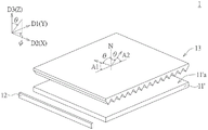
Fig. 1A is a schematic perspective view of a backlight module according to an embodiment of the present application. Fig. 1B is a schematic perspective view of a backlight module according to another embodiment of the present application. The difference between fig. 1A and fig. 1B is that the light guide plate 11 of fig. 1A includes a plurality of lenses 114 disposed on the main portion 11M, the light guide plate 11 'of fig. 1B may not include lenses, and the light guide plate 11' of fig. 1B may also optionally include other patterns instead of the lenses 114, such as convex or concave or other patterned structures, but is not limited thereto, and the above embodiments are all applicable to the light guide plate of the present application.
Fig. 2A is a schematic cross-sectional view of a light source and a light guide plate according to an embodiment of the present application. Fig. 2B is a top view of a light source and a light guide plate according to an embodiment of the disclosure. FIG. 2C is a simplified diagram of light exiting at a low horizontal included angle after the light from the light source of FIG. 2A passes through the light guide plate. Fig. 2A to 2C illustrate related components of the backlight module shown in fig. 1A as an example. In one embodiment, a backlight module 1 includes a light guide plate (light guide plate)11, a light source (light source)12 disposed adjacent to the light guide plate 11, and an optical sheet 13 disposed on the light guide plate 11. The light guide plate 11 has an upper surface 11a (light exit surface), a lower surface 11b and a light modulating structure 112, wherein the light modulating structure 112 is located on the lower surface 11 b; the optical sheet 13 is disposed opposite to the upper surface 11a of the light guide plate 11. In this example, the light guide plate 11 includes a main portion 11M and a plurality of lenses (lenses) 114 provided on the upper surface 11 of the main portion 11MMa(ii) a Further, for example, a line connecting the highest points of the lenses 114 is used as the upper surface 11a of the light guide plate 11. In one embodiment, the lower surface 11b may be substantially equal to the lower surface of the main portion 11M. According to the embodiment, the light emitted from the light source 12 passes through the upper surface 11a of the light guide plate 11 and becomes the outgoing light ray OL, and the outgoing light ray OL has a brightness distribution in the normal direction ND (for example, the first direction D1) parallel to the incoming light surface 110; in this example, light emitted from the light source 12 passes through the main portion 11M and the lens 114 to be the outgoing light OL, as shown in fig. 2C. In fig. 2C, a simple example is shown in which only a single dimming structure 112 is used to emit light from the upper surface 11a of the light guide plate 11 (i.e., through the lens 114) after the light guiding structure 112 totally reflects the guided light, and then the light is emitted at a low-level included angleThe optical structures 112 may be distributed on the lower surface 11b of the light guide plate 11 in an equidistant, non-equidistant or random arrangement, depending on the design requirements. The light incident surface 110 may have a slight roughness, but two adjacent sides of the light incident surface respectively have two substantially extending directions, and a plane formed by the two directions is a light emitting surface, or a plane for finding the average height of the relief of the light incident surface is defined as the light emitting surface of the light guide plate.
In another embodiment, the upper surface 11 'a of the light guide plate 11' is the upper surface 11 of the main portion of the light guide plate in FIG. 1BMa(ii) a If the light guide plate further includes other patterns, the upper surface 11' a of the light guide plate is a surface formed by connecting the highest points of the patterns. The light emitted from the light source 12 passes through the upper surface 11' a of the light guide plate 11 and becomes the outgoing light ray OL, and the outgoing light ray OL has a brightness distribution in a normal direction ND (e.g., the first direction D1) parallel to the incoming light surface 110.
In this example, as shown in fig. 1A, 2A, and 2B, the first direction D1(e.g. y-direction) and the second direction D2(e.g. x-direction), the first direction D1 may be substantially perpendicular to the second direction D2, the light source 12 includes a plurality of light emitting elements, such as light emitting diodes, the light emitting elements are disposed along the second direction D2, for example (but not limited to), and the distance between the light guide plate 11 and the light source 12 is from near to far in the first direction D1, for example (but not limited to). The light emitted from the light source 12 has a first luminance distribution in the first direction D1 (fig. 2A and 2B) after passing through the light guide plate 11. In this example, the third direction D3(e.g. z-direction) is a normal direction of the plane (XY plane) in which the first direction D1 and the second direction D2 are located.
FIG. 3 is a graph of conoscopic polarization measured by a conoscope at a position approximately near the geometric center of a light guide plate after light passes through the light guide plate according to an embodiment of the present disclosure; FIG. 3 is a view of the light guide plate of FIG. 1A as measured at a position substantially near the geometric center of the top surface of the light guide plate, or the light guide plate of FIG. 1B as measured at a position substantially near the geometric center of the top surface of the light guide plate. The following selective combination with fig. 1A is an exemplary illustration, and does not limit the light guide plate aspect of the present invention.
Referring to fig. 1A and fig. 3, the marked scales (20, 40, 60, 80) of the dotted circles arranged in a concentric manner in fig. 3 are included angles θ, which represent the included angles between the light rays of the measuring points and the third direction D3(e.g., the Z-direction in fig. 1A); the plurality of lines in fig. 3 radiating outward from the center of the circle, i.e., the outermost circles are marked with the indices (0, 30, 60,. eta., 330) as the azimuth angle phi, which is the distribution of light parallel to the counterclockwise measurement points on the XY plane as shown in fig. 1A. In this example, the angle defining the azimuth angle phi of 90 degrees from the third direction D3(e.g. z-direction) to the first direction D1(e.g. y-direction) in fig. 3 is positive, that is, the angle of the angle theta is greater than zero and equal to or less than 80 degrees, which means the tilt angle direction from the front viewing angle to the direction away from the light source 12 (i.e. the viewer tilts from the front viewing angle to the direction away from the light source 12 to view a display area); in fig. 3, the angle between the included angle θ and the first direction D1 and the azimuthal angle Φ of the second direction D2 is negative, i.e. the angle between the included angle θ and the second direction D2 is less than zero and equal to or greater than-80 degrees, so that the included angle is the direction from the positive viewing angle to the tilt angle closer to the light source 12 (i.e. the viewer tilts from the positive viewing angle to the direction closer to the light source 12 to view a display area). Moreover, the area marked on fig. 3 is a profile of the measured luminance values nits in different interval ranges (0, 2000, 4000, 16000), which can be set arbitrarily, and only the relative relationship of the luminance distribution in the conoscopic polarization diagram within the limited range can be observed.
Please refer to fig. 1A, 2A, and 2B. The conoscopic polarization diagram of fig. 3 shows that the light-exiting direction of the light source 12 after passing through the light guide plate 11 has high luminance distributions, for example, in two tilt angle ranges substantially along the first direction D1(e.g. y-direction) and inclined toward and away from the light source 12 (i.e. away from the front viewing angle) relative to the third direction D3(e.g. z-direction), and the luminance distributions of the two are similar, while the middle front viewing angle (horizontal viewing angle 0 degree) to the absolute value of the included angle θ of about 60 degrees has a very low luminance distribution, which is substantially less than 15% of the maximum luminance, so that the range with the absolute value of the included angle θ greater than 70 degrees is concentrated on the range with the luminance greater than 50% of the maximum luminance.
As shown in the conoscopic polarization diagram of fig. 3, brightness values greater than 2000nits begin to appear at angles θ greater than 60 degrees in absolute value along the azimuthal angle Φ between 90 and 270 degrees, i.e., along the first direction D1(e.g., y-direction). The brightness distribution is similar in the upper and lower two viewing angle regions where the first and second maximum brightness occur. For example, when the angle θ is greater than 60 degrees and the azimuth angle Φ is 70 degrees to 110 degrees, a luminance distribution having a luminance value greater than 2000nits begins, that is, when the angle θ is greater than 60 degrees and the luminance value is greater than 2000nits, the azimuth angle Φ distribution range of the luminance distribution is 40 degrees (110 degrees-70 degrees — 40 degrees). For another example, when the angle θ is smaller than-60 degrees and the azimuth angle Φ is 245 degrees to 295 degrees, a luminance distribution with a luminance value larger than 2000nits begins, that is, when the absolute value of the angle θ is larger than 60 degrees and the azimuth angle Φ of the luminance distribution with a luminance value larger than 2000nits is within 50 degrees (295 degrees to 245 degrees, 50 degrees).
Compared with the prior light guide plate, the brightness distribution is only concentrated in a single visual angle area distribution, or the range of the absolute value of the azimuth angle difference and the absolute value of the depression angle difference in a brightness distribution range with larger brightness is larger, and the obvious brightness distribution is not concentrated compared with the diffusion of the invention. Therefore, according to the light guide plate design proposed in the embodiment of the present application, in the direction of the larger top tilt angle (larger absolute value of the included angle θ) of the light guide plate along the first direction D1(e.g. y-direction), the first maximum luminance and the second maximum luminance with the luminance values (normalized luminance values) closer to and further away from the light source 12 appear in the two viewing angle regions, and the luminance distribution pattern of the two viewing angle regions is similar.
Fig. 4 is a graph illustrating a first luminance distribution along a first direction D1 after light emitted from a light source passes through a light guide plate according to an embodiment of the present disclosure. As shown in the coordinate diagram of fig. 3, the along-line direction formed by the angles of the azimuth angle Φ at 90 degrees and at 270 degrees corresponds to the exemplary first direction D1, and thus, in this example, fig. 4 also shows the first luminance distribution in which the angle θ of the azimuth angle Φ in fig. 3 is from 0 degree to 80 degrees and from 0 degree to-80 degrees in the along-line direction of 90 degrees to 270 degrees (i.e., in the first direction D1).
Therefore, the horizontal axis of fig. 4 represents the tilt angle range from-80 degrees to 0 degrees to 80 degrees along the first direction D1 and the angle θ between the third direction D3(e.g. z-direction), which corresponds to the tilt angle from the direction close to the light source 12 to the front view angle to the direction away from the light source 12; the ordinate of fig. 4 is the normalized percentage luminance result (hereinafter referred to as normalized luminance) obtained by averaging (normalizing) the luminance at the angle θ in fig. 3 with respect to one of the maximum luminances. Referring to fig. 4 and fig. 2C again, the larger the angle θ, the smaller the angle between the horizontal plane and the first direction D1 and the horizontal plane and the second direction D2, the larger the angle θ, the smaller the brightness distribution of the light emitting angle obtained by the light emitted from the light source 12 passing through the light guide plate 11 and passing through the light guide plate dimming structure 112 is mainly concentrated in the direction of the lower horizontal angle.
As shown in fig. 4, in an embodiment, the first luminance distribution of the light emitted from the light source 12 after passing through the light guide plate 11 is a normalized luminance distribution along the first direction D1(e.g. y-direction, which is equivalent to the angle of the upper azimuth angle Φ in the line direction of 90 degrees to 270 degrees in fig. 3) at different angles θ, and it can be seen that the two viewing angle regions corresponding to the larger angle θ away from the third direction D3(e.g. z-direction) of the light guide plate 11 have the first maximum luminance B1 and the second maximum luminance B2, respectively. Normalized to 100% brightness at a first maximum brightness B1. The first maximum brightness corresponds to the first angle theta11The second maximum brightness corresponds to a second angle theta12First angle theta11Is equal to the second angle theta12The absolute value of the angle of (b) is greater than 60 degrees, wherein the absolute value of the difference between the first maximum luminance and the second maximum luminance is less than or equal to 30% of the first maximum luminance (≦ 30% x the first maximum luminance). In one example, the first angle θ11And a second angle theta12Respectively, the angles between the first direction D1 and a normal direction N of a light-emitting surface (e.g., the upper surface 11a) of the light guide plate 11 are included.
Referring to fig. 1A, 2B and 4, the first direction D1(e.g. y-direction) can be defined as the vertical viewing angle for viewing a display device, and the second direction D2(e.g. x-direction) can be defined as the horizontal viewing angle for viewing a display device. A first maximum brightness in the first direction D1 corresponding to a first angle as described herein, the absolute value of the first angle being the angular absolute value of the difference between the tilt angle of the top view and 0 degrees. For example, in a non-limiting exampleIn the right half of the graph of FIG. 4, the angle corresponding to the included angle θ is approximately between-75 degrees and-80 degrees with the maximum brightness B1, the first angle θ11Is, for example, 75 degrees to 80 degrees, which corresponds to a maximum luminance B1 of about 100% (normalized luminance), B1 being the first maximum luminance of this example.
A second maximum brightness in the first direction D1 corresponding to a second angle, as described herein, the absolute value of which is the angular absolute value of the difference between the tilt angle of the top view and 0 degrees. For example, in a non-limiting example, the angle corresponding to the included angle θ in the left half of the graph of FIG. 4 has a maximum brightness B2 between 75 degrees and 80 degrees, and the second angle θ12Is, for example, between 75 degrees and 80 degrees, which corresponds to a maximum luminance B2 of about 70% to 80% (normalized luminance), B2 being the second maximum luminance for this example.
In the example shown in fig. 4, the absolute value of the difference between the first maximum luminance and the second maximum luminance is, for example, equal to or less than 30% of the first maximum luminance (≦ 30% × the first maximum luminance). In another embodiment, the absolute value of the difference between the first maximum luminance and the second maximum luminance is, for example, equal to or less than 20% of the first maximum luminance (≦ 20% x the first maximum luminance). In another embodiment, the absolute value of the difference between the first maximum luminance and the second maximum luminance is, for example, equal to or less than 30% of the second maximum luminance (≦ 30% x the second maximum luminance). In another embodiment, the absolute value of the difference between the first maximum luminance and the second maximum luminance is, for example, equal to or less than 20% of the second maximum luminance (≦ 20% x the second maximum luminance). The smaller the absolute value of the difference of the maximum brightness is, the better the adjusting effect of the light adjusting structure 112 of the light guide plate is.
Referring to fig. 4 again, in another embodiment, the absolute value of the included angle θ in the first direction D1 is less than or equal to about 60 degrees, which has a very low brightness distribution, and is substantially less than 15% of the maximum brightness; and the brightness of more than 50% of the maximum brightness is concentrated in the range of the absolute value of the included angle theta of more than 70 degrees. The smaller the angle range of the light guide plate with the brightness greater than 50% of the maximum brightness is, the better the adjustment effect of the light adjusting structure 112 of the light guide plate is.
Furthermore, the first luminance distribution is an asymmetric curve such as but not limited to a curve with an included angle θ equal to 0 degrees along a vertical viewing angle of a display device, i.e., the first maximum luminance and the second maximum luminance may not be equal, as shown in fig. 4. In one example, the first maximum brightness is greater than or equal to the second maximum brightness; in a practical application (as shown in fig. 1A), the position of the first maximum luminance (e.g. B1 of fig. 4) generated by the light emitted from the light source 12 after passing through the light guide plate 11 is closer to the light source 12 than the position of the second maximum luminance (e.g. B2 of fig. 4) or the position of the included angle θ (θ:0 to-80 degrees) having a negative value in the third direction D3(e.g. z-direction). In other words, the light emitted from the light source 12 passes through the light guide plate 11 and then has a first brightness distribution in the first direction D1 and at an angle θ with respect to the third direction D3, and a first maximum brightness and a second maximum brightness of the first brightness distribution respectively appear in the first direction D1 in a first viewing angle area a1 and a second viewing angle area a2 corresponding to a top-down tilt angle of the light guide plate 11, and the first viewing angle area a1 has a greater brightness than the second viewing angle area a 2. In another example, through the design of the dimming structure 112, the maximum brightness value of the second viewing angle region a2 may be greater than the maximum brightness value of the first viewing angle region a1, as long as the maximum brightness distribution is a distribution in which the absolute angle value of the first angle and the absolute angle value of the second angle are greater than 60 degrees, respectively.
In addition, in an embodiment, after the light emitted from the light source passes through the light guide plate, the light has a first luminance distribution in the first direction D1, and a luminance value of the first luminance distribution in the first direction D1 corresponding to an angle θ (an angle between the angle θ and the third direction D3(e.g. z-direction)) is equal to 60 degrees and is less than 15% of the first maximum luminance. In another embodiment, the light emitted from the light source has a second luminance distribution in the first direction D1 after passing through the light guide plate and the optical sheet (as shown in fig. 6 described later), and the luminance value of the second luminance distribution in the first direction D1 corresponding to the included angle θ is equal to 60 degrees and is less than 15% of the first maximum luminance. In another embodiment, the luminance values of the first luminance distributions in the first direction D1 corresponding to the angle θ having the absolute value equal to 60 degrees are less than 15% of the second maximum luminance. In another embodiment, the luminance values of the second luminance distribution in the first direction D1 corresponding to the angle θ having the absolute value equal to 60 degrees are less than 15% of the second maximum luminance. As shown in fig. 4, the first luminance is distributed in the first direction D1 at a luminance value B3 corresponding to an angle θ of-60 degrees (the absolute value of the angle is equal to 60 degrees) which is less than 15% (i.e., 100% × 0.15 is 15%, 10% < 15%) of the first maximum luminance (the maximum luminance B1 shown in fig. 4, about 100% normalized luminance). And the luminance value B4 of the first luminance distribution in the first direction D1 corresponding to the angle θ of 60 degrees (the absolute value of the angle is 60 degrees) is less than 15% of the second maximum luminance (the maximum luminance B2 shown in fig. 4, about 76% normalized luminance) (i.e., 0.76% × 15.4%, 6% < 11.4%).
In addition, in other embodiments, the absolute value of the first angle and the absolute value of the second angle are, for example, greater than 70 degrees, greater than 75 degrees, greater than 80 degrees, or greater than 85 degrees, respectively, and the greater the absolute value of the first angle or the second angle is, the more concentrated the dimming effect of the light guide plate is. This is not to be considered limiting in any way. The present application can make a first angle corresponding to a first maximum brightness and a second angle corresponding to a second maximum brightness, that is, a first viewing angle and a second viewing angle of a vertical viewing angle for viewing the display device, which have absolute angle values greater than 60 degrees, respectively, by designing the dimming structure, such as a ratio of a height to a maximum width (e.g., a radial dimension), a haze value, and/or a refractive index.
According to the embodiment, the light-adjusting structures 112 on the lower surface 11b of the light guide plate 11 have high transmittance and extremely low haze values, for example, the haze values of the light-adjusting structures 112 are greater than or equal to 0% and less than or equal to 10%, or less than or equal to 5%, or less than or equal to 1%. Furthermore, the light adjusting structure 112 of the embodiment may be prepared by printing dots, inkjet printing, photopolymerization, or extrusion molding or injection molding, and is discontinuously distributed on the lower surface 11b of the light guide plate 11, so that the material of the light adjusting structure 112 of the embodiment may be different from or the same as the material of the light guide plate 11, which is not limited in this application. In an example, the light adjusting structures 112 are, for example, transparent ink, and transparent ink dots are printed on the lower surface 11b of the light guide plate 11 by screen printing. In contrast to conventional screen printing inks, the clear inks of one embodiment contain very little or no particles (beads for light scattering). In one example, the absolute value of the difference between the refractive index of the light adjusting structure 112 and the refractive index of the light guide plate 11 is, for example, in a range from 0 (the same material) to 0.1 (different materials), or in a range from 0 to 0.2 (or 0 or more and 0.2 or less). The light modulating structure 112 may also be one or more refractive index settings; this is not to be considered limiting in any way.
Furthermore, in one embodiment, the light can exit the light guide plate 11 at a low horizontal angle through the ratio of the height to the width (e.g., radial dimension) of the light modulating structure 112. Referring to fig. 2A again, the light-adjusting structure 112 has a contact area Ac with the lower surface 11b of the light guide plate 11, in an example, the height H of the light-adjusting structure 112A(maximum height) and contact area ACMaximum width D ofAIs for example less than 0.02 (i.e.H)A/DA<0.02). If the light modulation structure 112 has a circular contact area, the maximum width of the light modulation structure is the diameter of the contact area, but the present application is not limited thereto. Furthermore, the cross-sectional shape of the light-adjusting structure 112 is not limited to the arc-shaped cross-section shown in the drawings, and may be other cross-sections such as a triangular or trapezoidal cross-section, or other regular or irregular cross-sections, as long as the height H of the light-adjusting structure 112 is equal toAAnd contact area ACMaximum width D ofAThe ratio of (a) is within the range of the embodiment, for example, less than 0.02, which is the applicable aspect of the dimming structure of the present application. The light-adjusting structure 112 can also be configured with the same refractive index or a mixture of different refractive indexes, and can be configured with the same or different HA/DAThe two factors have an influence on the adjustment of the light emitting direction, so that the design space for adjusting the light emitting direction is more flexible.
Furthermore, the height H of the light-adjusting structure 112AThe drop also benefits light leaving the light guide plate 11 at low horizontal angles. In one example, the dimming structure 112 is in a third direction D3(e.g., Z-direction)) Has a maximum height HAMaximum height HAFor example, but not limited to, less than 7 μm, or less than 3 μm, or less than 1 μm. In practical applications, the maximum height H of the light-adjusting structure 112AAccording to its maximum width DAAnd then.
In addition, in an embodiment, the lens 114 disposed on the main portion 11M of the light guide plate 11 is as shown in fig. 1A, 2A and 2B, wherein the height h of the lens 114LSet pitch (pitch) P relative to the lensesLA ratio (height/set pitch) of (a) is, for example, in the range of 0.16 to 0.4. The material of the lens 114 may be the same as or different from the material of the main portion 11M, and may have good light transmittance. The light guide plate 11 may be made of a light-transmitting resin material, or the light-transmitting resin material may contain additives such as a UV absorber, an antistatic agent, an antioxidant, a processing stabilizer, a flame retardant, a lubricant, and the like, and two or more of them may be used in combination. For example, in one example, when the light guide plate is made of a light-transmitting resin to which a UV absorber is added, the light guide plate is prevented from being deteriorated by ultraviolet rays among light rays. The light guide plate is generally made of a light-transmitting resin containing no light diffusing agent. This application is to the chooseing for use of light guide plate material, as long as do not influence the light-emitting of light guide plate that light passes through the embodiment, do not do the restriction more.
It should be noted that, although fig. 1A and fig. 2A-2C illustrate examples in which the light guide plate 11 includes the main portion 11M and the lens 114, a cone polarization diagram measured after light passes through the light guide plate 11 formed by the main portion 11M and the lens 114 and a first luminance distribution curve along the first direction D1 are illustrated in fig. 3 and 4. However, the present application is not limited to the light guide plate shown in fig. 1A and fig. 2A to 2C.
Another embodiment of the present application provides a backlight module, the components of which are shown in fig. 1A and 1B, including a light guide plate 11/11 ', a light source 12 disposed adjacent to the light guide plate 11/11 ', and an optical sheet 13 disposed on the light guide plate 11/11 '. When the light emitted from the light source passes through the light guide plate 11/11' and the optical sheet 13, the collimating effect can be achieved.
FIG. 5 shows an embodiment of the present applicationThe cross-sectional view of an optical sheet in the backlight module is shown. Please refer to fig. 1A and fig. 5. In this embodiment, for example, a reverse prism sheet is used as the optical sheet 13 disposed opposite to the upper surface 11A of the light guide plate 11 shown in fig. 1A. The optical sheet 13 includes a first surface 13a and a plurality of prisms 134 disposed on the first surface 13 a. Height H of prism 134TWidth W of bottomTA ratio of (b) is, for example, 3.8 or less and 1.6 or more (i.e.1.6 ≦ HT/WT≦ 3.8). In one example, the upper surface 11 of the main section 11M in the light guide plate 11 shown in fig. 1AMaThe lenses 114 (e.g., semi-cylindrical or arc-shaped lenses) are disposed with the lens-disposing axial directions (e.g., along the first direction D1) orthogonal to the lens-disposing axial directions (e.g., along the second direction D2) of the prisms 134 of the optical sheet 13 (fig. 1). In another example, the axial direction (e.g., along the first direction D1) of the lens 114 and the axial direction (e.g., along the second direction D2) of the prism 134 of the optical sheet 13 form an included angle of 87 degrees to 93 degrees, so that the undesirable phenomenon of interference fringes can be reduced by the design of the display panel.
Fig. 6 is a graph of one of second luminance distributions in the first direction D1 and a graph of one of third luminance distributions in the second direction D2 after light emitted from the light source passes through the light guide plate 11 and the optical sheet 13 in an example of the present application. In one embodiment, the second direction D2(e.g. x-direction) is, for example, perpendicular to the first direction D1(e.g. y-direction). After passing through the light guide plate 11 and the optical sheet 13, light emitted from the light source 12 has a second luminance distribution in which an absolute value of an angle θ is in a range from 0 degree to 80 degrees along a line direction having an azimuth angle Φ of 90 degrees and 270 degrees in the first direction D1, and has a third luminance distribution in which the absolute value of the angle θ is in a range from 0 degree to 80 degrees along the direction having the azimuth angle Φ of 0 degrees and 180 degrees in the second direction D2, wherein the half luminance width (HW) of the second luminance distribution is in a range of a half luminance width (HW) of the second luminance distribution, which is a range of a difference absolute value of the angle θ when the normalized luminance value is 50%, for example, a range of the half luminance width (HW) of the second luminance distribution is 25 degrees or less (≦ 25 degrees), or 20 degrees or less (15 degrees). The range of the half-luminance width of the third luminance distribution (the range of the angle θ) is, for example, 35 degrees or less (≦) or 30 degrees or less. The range (range of the angle θ) in which the third luminance distribution is larger than the width of 10% of the luminance value (10% of the maximum luminance of the third luminance distribution) is, for example, 60 degrees or less (≦ 60 degrees or 50 degrees. The second and third luminance distributions are changed by the first luminance distribution of the light passing through the light guide plate 11 and the prism structure of the light passing through the different optical sheets 13.
The following is an illustration of FIG. 1A, but is not intended to limit the present invention. Reference may be made to fig. 1A, 5, 6 simultaneously. As shown in fig. 6, the second luminance distribution in the first direction D1 is not a symmetric curve with respect to the 0 degree viewing angle, and in this example, the half luminance width (HW) (the range of the included angle θ) is about 13 degrees, for example; the half-luminance width (range of the angle θ) of the third luminance distribution in the second direction D2 is, for example, about 30 degrees; and the width of the 10% luminance value of the third luminance distribution in the second direction D2 is, for example, about 60 degrees. For example, in fig. 6, the angle corresponding to 10% luminance value in the right half area of the curve of the third luminance distribution in the second direction D2 is about-25 degrees, and the angle of 10% or less of the luminance value is in the range of-25 degrees or less, that is, the luminance value is lower than 10% when the absolute value of the angle is greater than 25 degrees. For example, in fig. 6, the angle corresponding to the 10% luminance value in the left half area of the curve of the third luminance distribution in the second direction D2 is about 25 degrees, and the absolute value of the angle of the 10% or less luminance value is in the range of 25 degrees or more. Therefore, after the light emitted from the light source passes through the light guide plate 11 and the optical sheet 13, the light source with the brightness value of more than 10% in the second direction D2 is mainly focused in the range with the absolute angle value less than 25 degrees, and the backlight module designed in this way has the function of light concentration. After light emitted from the light source passes through the light guide plate 11 and the optical sheet 13, the luminance value in the second direction D2 is 10% or less of the maximum luminance when the absolute value of the angle is 25 degrees or more. In one embodiment, when the observer views the display panel of the application embodiment at a viewing angle with an inclination angle greater than 25 degrees relative to the normal direction N of the display panel in the second direction D2(e.g. in a horizontal viewing angle), since the brightness value is less than or equal to 10%, it is difficult to clearly view the information on the display screen, and it is not easy for the ordinary observer to clearly recognize the change of the brightness difference, thereby having the effect of preventing the information on the display screen of the display device from being snooped by surrounding observers.
Fig. 7A is a conoscopic polarization diagram measured by a conoscope after light passes through the light guide plate and the optical sheet according to an embodiment of the present disclosure. Fig. 7B is a schematic diagram of a simulation result of a luminance distribution of light emitted from the light source after passing through the light guide plate 11, the optical sheet 13 and a display panel, in which a cone polarization diagram of 0.5% normalized luminance is marked on the diagram, a central region surrounded by lines in the diagram is a region having luminance greater than 0.5% normalized luminance, and left and right side regions other than the surrounded central region, for example, a region greater than an absolute value of an angle of about 40 degrees in the second direction D2 is a region having luminance less than 0.5% normalized luminance. Fig. 7A clearly shows that the light-emitting luminance distribution of the backlight module is very concentrated after the light passes through the light guide plate 11 and the optical sheets 13 of the embodiment, while fig. 7B shows a simulation result of the light-emitting luminance distribution after the light passes through the light guide plate 11, the optical sheets 13 and the display panel of the embodiment, and the light is concentrated in the central area viewed by the observer to achieve an excellent collimated light effect. In addition, because the light-emitting brightness of the left and right regions is extremely low, observers (with the inclination angle of the viewing angle of 40 degrees or more, for example) positioned at the left and right sides of the central region are difficult to clearly see the picture information displayed on the display panel, and further, additional effects of peeping prevention and information confidentiality can be achieved.
In an embodiment, after the light emitted from the light source 12 passes through the light guide plate 11 and the optical sheet 13, in the second luminance distribution formed in the first direction D1, the absolute value of the angle is greater than or equal to (≧)25 degrees, which corresponds to a luminance, and is less than or equal to 10% of the maximum luminance of the second luminance distribution. As shown in fig. 6, the maximum luminance of the second luminance distribution of this example is 100%, and the luminance corresponding to the absolute value of the angle of the second luminance distribution equal to 25 degrees is about 8% and 5%, both of which are lower than 10% of the maximum luminance. Moreover, the luminance corresponding to the second luminance distribution when the absolute value of the angle is greater than 25 degrees is lower.
In an embodiment, after the light emitted from the light source 12 passes through the light guide plate 11 and the optical sheet 13, in a third luminance distribution formed in the second direction D2, the absolute value of the angle is greater than or equal to (≧)35 degrees, which corresponds to a luminance, and is less than or equal to 10% of the maximum luminance of the third luminance distribution. As shown in fig. 6, the maximum luminance of the third luminance distribution of this example is 100%, and the luminance corresponding to the third luminance distribution having an absolute value of the angle equal to 35 degrees is about 4% and 3%, both of which are lower than 10% of the maximum luminance. And when the absolute value of the angle of the third brightness distribution is larger than 35 degrees, the corresponding brightness is lower.
In addition, in an example, the optical sheet 13 includes a plurality of prisms 134 disposed on the first surface 13a thereof, wherein the prisms 134 may have a prism included angle θ1(FIG. 5) is, for example, but not limited to, a range of 62 degrees to 72 degrees. In one example, the included angle θ between two adjacent prisms 1342For example, but not limited to, 87 degrees to 93 degrees. The design concept of the light guide plate is to concentrate the light of the light source passing through the light guide plate towards the direction of the absolute value of a larger angle through the design of the light adjusting structure, so that the light source distribution in the range of the absolute value of a smaller angle is reduced, namely, the light source distribution of the absolute value of a large angle is increased. And the included angle theta of the prism1Or angle theta2The design of (1) is mainly designed according to Snell's law, and the effect is that the light emitted by the light source can be matched with the light which is concentrated at a large angle after passing through the light guide plate 11, so that the effect of concentrating towards a central angle can be achieved; the plurality of prisms 134 of the optical sheet 13 are designed to enable light emitted from the light source to have a better light-collecting effect after passing through the light guide plate 11 and the optical sheet 13. Furthermore, in one example, the pitch P of the prisms 134 is setT(pitch) is less than 100 μm. Of course, these values are merely exemplary and may be modified and adjusted according to the actual application conditions.
The following experiments were performed on the refractive index and the configuration of the light modulating structure on the light guide plate in the examples, and several sets of the experimental results are presented below.
Fig. 8A is a graph of a first luminance distribution in a first direction after light emitted from a light source passes through a light guide plate in several sets of experiments. Fig. 8B is a graph of a third luminance distribution in the second direction after light emitted from the light source passes through the light guide plate and the optical sheet in several sets of experiments. The luminance distributions in fig. 8A and 8B can be described with reference to the luminance distributions in fig. 4 and 6, respectively, and will not be described again here.
Wherein the refractive index of the light guide plate is 1.55. The relevant physical parameters of the dimming structure represented by each curve in fig. 8A and 8B are as follows. .
Curve E1: the refractive index of the light modulating structure is 1.49, the height of one light modulating structure (see H in FIG. 2A)A) 4.19 μm, maximum width (see D in FIG. 2A)A) 382.60 μm, HA/DAThe ratio of (A) to (B) is 0.011.
Curve E2: the refractive index of the light modulating structure is 1.49, the height of one light modulating structure (see H in FIG. 2A)A) 6.95 μm, maximum width (see D in FIG. 2A)A) 388.89 μm, HA/DAThe ratio of (A) to (B) was 0.018.
Curve C1: the refractive index of the light modulating structure is 1.4, the height of one light modulating structure (see H in FIG. 2A)A) 12.53 μm, maximum width (see D in FIG. 2A)A) 388.40 μm, HA/DAThe ratio of (A) to (B) is 0.032.
Curve C2: the refractive index of the light modulating structure is 1.55, and the height of one light modulating structure (see H in FIG. 2A)A) 15.36 μm, maximum width (see D in FIG. 2A)A) 328.57 μm, HA/DAThe ratio of (A) to (B) is 0.047.
As shown in FIG. 8A, HA/DAThe higher the ratio (e.g., curve C2), the lower the brightness value in the first brightness distribution corresponding to an angle of about-75 degrees. And HA/DAThe dimming structure of the embodiment (e.g., curves E1, E2) having a ratio of less than 0.02 corresponds to a relatively high brightness value (e.g., above 87%) for angles of about 75 degrees and-78 degrees. Furthermore, as shown in FIG. 8B, in a third luminance distribution curve in the second direction after the light passes through the light guide plate and the optical sheet, HA/DAThe lower the ratio of (e.g., curves E1, E2), the greater the absolute value of the angle at which 10% or less of the maximum luminance of the third luminance distribution is greater than 35 degrees, the better the peep prevention effect can be achieved, and if greater than 30 degrees can be achieved. As shown in fig. 8B, the light passes through the light guide plate and the optical sheet and then passes through the second directionIn the third luminance distribution curve of (1), HA/DAThe higher the ratio (e.g., curve C2), the greater the absolute value of the angle at which the maximum luminance of the third luminance distribution is greater than 10% is than HA/DAThe lower ratio (e.g. curves E1, E2) can achieve better light collection effect.
As shown in fig. 8B, the refractive index size (C1)<E1=E2<C2) And HA/DAMagnitude of ratio (E1)<E2<C1<C2) Which contributes to the influence of the third luminance distribution. Furthermore, the refractive index size (C1)<E1=E2<C2) And HA/DAMagnitude of ratio (E1)<E2<C1<C2) The light pattern or brightness distribution of the light emitted from the light source 12 after passing through the light guide plate 11, the light source 12 after passing through the light guide plate 11 and the optical sheet 13, and the light emitted from the light source 12 after passing through the light guide plate 11 or the optical sheet 13 and the display panel can also contribute to the light pattern or brightness distribution of the light, and whether the expected result of the design can be achieved can be determined by measuring the conoscopic polarization diagram, which is not described herein.
Furthermore, the backlight module of this embodiment may further include other optical films such as a Brightness Enhancement Film (BEF) or a diffusion film, depending on the actual application. Other components can also be included, such as a reflective sheet disposed under the light guide plate, or a reflective side sticker disposed on the side of the light guide plate. FIG. 9 is a schematic cross-sectional view of a light guide plate according to another embodiment of the present application. Like elements in fig. 9 and fig. 2A are labeled with the same numerals, so details of related layers and components in fig. 9, including elements/layers and their spatial arrangement, etc., please refer to fig. 2A, which is not repeated herein. As shown in fig. 9, a reflective side sticker 30, such as a silver reflective side sticker, may be disposed on a side surface 11c of the light guide plate 11 away from the light source, so as to increase the chance of reflection for light rays that do not pass through the light modulation structure 112, and maintain the light rays at a low light-emitting angle with a high ratio.
In summary, the embodiments provide a backlight module, particularly a backlight module including a light guide plate having a light adjusting structure, so that light passing through the light guide plate has a large light-emitting angle. In one embodiment, the light guide plate is combined with an appropriate optical sheet (such as a reverse prism sheet) to provide a backlight module with collimated light. Moreover, the light guide plate can be manufactured in a simple manner to form the dimming structure provided in the above embodiments, for example, when the dimming structure is applied to manufacturing of a medium-sized or large-sized backlight module, if the dimming structure of the embodiments is formed in a screen printing manner, not only an optimized collimated light effect can be achieved, but also the cost can be greatly saved, and the dimming structure is suitable for mass production.
Other embodiments, such as different arrangements and arrangements of known components of the device, or different materials for the related devices, may also be applied, such as the structure, pattern, material, etc. of the light guide plate and the optical sheet, which may be adjusted or changed according to the actual requirements and conditions of the application. Accordingly, the structures shown in the specification and drawings are illustrative only and are not intended to limit the scope of the present application. In addition, persons skilled in the art should understand that the shapes and positions of the components in the embodiments are not limited to the shapes illustrated in the drawings, and can be adjusted according to the requirements and/or manufacturing steps of the actual application without departing from the spirit of the present application.
Although the present invention has been described with respect to the preferred embodiments, it will be understood by those skilled in the art that various changes in form and details may be made therein without departing from the spirit and scope of the invention as defined by the appended claims.
Claims (9)
1. A backlight module, comprising:
the light guide plate is provided with an upper surface, a lower surface and a plurality of light adjusting structures, and the plurality of light adjusting structures are positioned on the lower surface;
an optical sheet disposed opposite to the upper surface of the light guide plate; and
a light source disposed adjacent to the light guide plate,
wherein the light emitted from the light source has a first brightness distribution in a first direction after passing through the light guide plate, the first brightness distribution has a first maximum brightness corresponding to a first angle and a second maximum brightness corresponding to a second angle, the absolute values of the first and second angles are respectively greater than 60 degrees,
wherein the absolute value of the difference between the first maximum brightness and the second maximum brightness is less than or equal to 30% of the first maximum brightness,
the first angle and the second angle are included angles with a normal direction of a light-emitting surface of the light guide plate in the first direction respectively.
2. The backlight module of claim 1, wherein the first luminance distribution has luminance values corresponding to an absolute value of an angle equal to 60 degrees in the first direction that are less than 15% of the first maximum luminance.
3. The backlight module of claim 1, wherein the first luminance distribution has a luminance value with an absolute value of an angle equal to 60 degrees less than 15% of the second maximum luminance.
4. The backlight module of claim 1, wherein light emitted from the light source has a second luminance distribution in the first direction after passing through the light guide plate and the optical sheet, the second luminance distribution having a half luminance width, the half luminance width being less than or equal to 25 °.
5. The backlight module of claim 4, wherein light emitted from the light source has a third luminance distribution in a second direction after passing through the light guide plate and the optical sheet, the second direction is perpendicular to the first direction, and an absolute value of an angle in the third luminance distribution is greater than or equal to 35 degrees and less than or equal to 10% of a maximum luminance of the third luminance distribution.
6. The backlight module of claim 1, wherein one of the plurality of light modulating structures on the lower surface of the light guide plate has a maximum height and a maximum width, and a ratio of the maximum height to the maximum width is less than 0.02.
7. The backlight module of claim 6, wherein the maximum height is less than 7 μm.
8. A light guide plate comprises an upper surface, a lower surface and light modulation structures, wherein the light modulation structures are positioned on the lower surface; when light passes through the light guide plate, the light has a first brightness distribution in a first direction, the first brightness distribution has a first maximum brightness and a second maximum brightness, the first maximum brightness corresponds to a first angle, the second maximum brightness corresponds to a second angle, the absolute value of the first angle and the absolute value of the second angle are respectively greater than 60 degrees,
wherein the absolute value of the difference between the first maximum brightness and the second maximum brightness is less than or equal to 30% of the first maximum brightness,
the first angle and the second angle are included angles with a normal direction of a light-emitting surface of the light guide plate in the first direction respectively.
9. A display device, comprising:
a display panel; and
a backlight module, comprising:
the light guide plate is provided with an upper surface, a lower surface and a plurality of light adjusting structures, and the plurality of light adjusting structures are positioned on the lower surface;
an optical sheet disposed opposite to the upper surface of the light guide plate; and
a light source disposed adjacent to the light guide plate,
wherein the light emitted from the light source has a first brightness distribution in a first direction after passing through the light guide plate, the first brightness distribution has a first maximum brightness corresponding to a first angle and a second maximum brightness corresponding to a second angle, the absolute values of the first and second angles are respectively greater than 60 degrees,
wherein the absolute value of the difference between the first maximum brightness and the second maximum brightness is less than or equal to 30% of the first maximum brightness,
the first angle and the second angle are included angles with a normal direction of a light-emitting surface of the light guide plate in the first direction respectively.
Priority Applications (2)
| Application Number | Priority Date | Filing Date | Title |
|---|---|---|---|
| CN201811407203.7A CN111221069B (en) | 2018-11-23 | 2018-11-23 | Backlight module and light guide plate thereof and display device using backlight module |
| US16/662,109 US11163102B2 (en) | 2018-11-23 | 2019-10-24 | Backlight module and light guide plate thereof and display device using the same |
Applications Claiming Priority (1)
| Application Number | Priority Date | Filing Date | Title |
|---|---|---|---|
| CN201811407203.7A CN111221069B (en) | 2018-11-23 | 2018-11-23 | Backlight module and light guide plate thereof and display device using backlight module |
Publications (2)
| Publication Number | Publication Date |
|---|---|
| CN111221069A CN111221069A (en) | 2020-06-02 |
| CN111221069B true CN111221069B (en) | 2022-04-12 |
Family
ID=70771438
Family Applications (1)
| Application Number | Title | Priority Date | Filing Date |
|---|---|---|---|
| CN201811407203.7A Active CN111221069B (en) | 2018-11-23 | 2018-11-23 | Backlight module and light guide plate thereof and display device using backlight module |
Country Status (2)
| Country | Link |
|---|---|
| US (1) | US11163102B2 (en) |
| CN (1) | CN111221069B (en) |
Citations (3)
| Publication number | Priority date | Publication date | Assignee | Title |
|---|---|---|---|---|
| CN104121517A (en) * | 2013-04-24 | 2014-10-29 | 鸿富锦精密工业(深圳)有限公司 | Backlight module |
| CN105911745A (en) * | 2016-06-29 | 2016-08-31 | 京东方科技集团股份有限公司 | Display device |
| CN108646465A (en) * | 2018-03-06 | 2018-10-12 | 友达光电股份有限公司 | Display device |
Family Cites Families (16)
| Publication number | Priority date | Publication date | Assignee | Title |
|---|---|---|---|---|
| JPH07248494A (en) * | 1994-03-14 | 1995-09-26 | Hitachi Ltd | Liquid crystal display device |
| US6356389B1 (en) * | 1999-11-12 | 2002-03-12 | Reflexite Corporation | Subwavelength optical microstructure light collimating films |
| JP2001188230A (en) * | 1999-12-28 | 2001-07-10 | Fuji Photo Film Co Ltd | Liquid crystal display device |
| JP2001215501A (en) * | 2000-02-02 | 2001-08-10 | Fuji Photo Film Co Ltd | Illumining device and liquid crystal display device |
| US20050046321A1 (en) * | 2001-10-31 | 2005-03-03 | Yoshinori Suga | Display apparatus |
| JP2006504116A (en) * | 2001-12-14 | 2006-02-02 | ディジタル・オプティクス・インターナショナル・コーポレイション | Uniform lighting system |
| US6880946B2 (en) * | 2002-01-15 | 2005-04-19 | Reflexite Corporation | Grooved optical microstructure light collimating films |
| JP4085377B2 (en) * | 2003-03-27 | 2008-05-14 | ミネベア株式会社 | Surface lighting device |
| US7320531B2 (en) * | 2003-03-28 | 2008-01-22 | Philips Lumileds Lighting Company, Llc | Multi-colored LED array with improved brightness profile and color uniformity |
| KR20070109134A (en) * | 2006-05-09 | 2007-11-15 | 엘지전자 주식회사 | Prism sheet, back light unit and liquid crystal display having the same |
| US8721149B2 (en) * | 2008-01-30 | 2014-05-13 | Qualcomm Mems Technologies, Inc. | Illumination device having a tapered light guide |
| US8905610B2 (en) * | 2009-01-26 | 2014-12-09 | Flex Lighting Ii, Llc | Light emitting device comprising a lightguide film |
| TWI438531B (en) | 2009-12-15 | 2014-05-21 | Ind Tech Res Inst | Planar light source module and optical film |
| US9651729B2 (en) * | 2010-04-16 | 2017-05-16 | Flex Lighting Ii, Llc | Reflective display comprising a frontlight with extraction features and a light redirecting optical element |
| JP5380580B2 (en) | 2011-06-07 | 2014-01-08 | 住友化学株式会社 | Light guide plate |
| TWI592722B (en) * | 2016-03-16 | 2017-07-21 | 揚昇照明股份有限公司 | Backlight module and display apparatus |
-
2018
- 2018-11-23 CN CN201811407203.7A patent/CN111221069B/en active Active
-
2019
- 2019-10-24 US US16/662,109 patent/US11163102B2/en active Active
Patent Citations (3)
| Publication number | Priority date | Publication date | Assignee | Title |
|---|---|---|---|---|
| CN104121517A (en) * | 2013-04-24 | 2014-10-29 | 鸿富锦精密工业(深圳)有限公司 | Backlight module |
| CN105911745A (en) * | 2016-06-29 | 2016-08-31 | 京东方科技集团股份有限公司 | Display device |
| CN108646465A (en) * | 2018-03-06 | 2018-10-12 | 友达光电股份有限公司 | Display device |
Also Published As
| Publication number | Publication date |
|---|---|
| CN111221069A (en) | 2020-06-02 |
| US20200166693A1 (en) | 2020-05-28 |
| US11163102B2 (en) | 2021-11-02 |
Similar Documents
| Publication | Publication Date | Title |
|---|---|---|
| CN107179627B (en) | Light source module and display device | |
| US7199930B2 (en) | Light modulation element | |
| US20160259115A1 (en) | Prism sheet, surface light source device, image source unit, and liquid crystal display device | |
| US7623293B2 (en) | Optical element and the light source apparatus utilizing the same | |
| TWI777073B (en) | Polarizing plate and optical display comprising the same | |
| WO2011074647A1 (en) | Light diffusing sheet and backlight using same | |
| WO2013121914A1 (en) | Lighting device and display device | |
| TWI663065B (en) | Polarizing plate and liquid crystal display having the same | |
| TWI428639B (en) | Diffuser plate, backlight unit and liquid crystal display having the same | |
| KR20160081784A (en) | Module for liquid crystal display apparatus and liquid crystal display apparatus comprising the same | |
| JP2014235896A (en) | Surface light source device, display unit, and luminaire | |
| US7248411B2 (en) | Optical film with array of microstructures and the light source apparatus utilizing the same | |
| JP5699375B2 (en) | Surface light source device, transmissive display device | |
| CN112379475A (en) | Display synergistic film and display device | |
| US10754083B2 (en) | Optical sheet for backlight unit and backlight unit | |
| CN111221069B (en) | Backlight module and light guide plate thereof and display device using backlight module | |
| US20110085108A1 (en) | Optical device, and backlight unit and liquid crystal display including the same | |
| JP2015180952A (en) | Prism sheet, surface light source device, video source unit, and liquid crystal display device | |
| JP6690190B2 (en) | Surface light source device, image source unit, and liquid crystal display device | |
| JP2015035252A (en) | Light source device, surface light source device, display device, and lighting device | |
| WO2022196162A1 (en) | Light diffusion sheet, backlight unit, liquid crystal display device, and information equipment | |
| WO2023210614A1 (en) | Light diffusion sheet, backlight unit, liquid crystal display device, and information equipment | |
| CN114035378B (en) | Display device | |
| WO2023145199A1 (en) | Optical sheet laminate, backlight unit, liquid crystal display device, information equipment, and production method for backlight unit | |
| US20240012184A1 (en) | Optical film and backlight module |
Legal Events
| Date | Code | Title | Description |
|---|---|---|---|
| PB01 | Publication | ||
| PB01 | Publication | ||
| SE01 | Entry into force of request for substantive examination | ||
| SE01 | Entry into force of request for substantive examination | ||
| GR01 | Patent grant | ||
| GR01 | Patent grant |