CN111212552B - An embedded cooling device in a server room - Google Patents
An embedded cooling device in a server room Download PDFInfo
- Publication number
- CN111212552B CN111212552B CN202010080860.6A CN202010080860A CN111212552B CN 111212552 B CN111212552 B CN 111212552B CN 202010080860 A CN202010080860 A CN 202010080860A CN 111212552 B CN111212552 B CN 111212552B
- Authority
- CN
- China
- Prior art keywords
- cavity
- chute
- gear
- fixedly arranged
- rotating shaft
- Prior art date
- Legal status (The legal status is an assumption and is not a legal conclusion. Google has not performed a legal analysis and makes no representation as to the accuracy of the status listed.)
- Expired - Fee Related
Links
Images


Classifications
-
- H—ELECTRICITY
- H05—ELECTRIC TECHNIQUES NOT OTHERWISE PROVIDED FOR
- H05K—PRINTED CIRCUITS; CASINGS OR CONSTRUCTIONAL DETAILS OF ELECTRIC APPARATUS; MANUFACTURE OF ASSEMBLAGES OF ELECTRICAL COMPONENTS
- H05K7/00—Constructional details common to different types of electric apparatus
- H05K7/20—Modifications to facilitate cooling, ventilating, or heating
- H05K7/20536—Modifications to facilitate cooling, ventilating, or heating for racks or cabinets of standardised dimensions, e.g. electronic racks for aircraft or telecommunication equipment
- H05K7/20554—Forced ventilation of a gaseous coolant
- H05K7/2059—Forced ventilation of a gaseous coolant within rooms for removing heat from cabinets, e.g. by air conditioning device
-
- A—HUMAN NECESSITIES
- A62—LIFE-SAVING; FIRE-FIGHTING
- A62C—FIRE-FIGHTING
- A62C3/00—Fire prevention, containment or extinguishing specially adapted for particular objects or places
- A62C3/16—Fire prevention, containment or extinguishing specially adapted for particular objects or places in electrical installations, e.g. cableways
-
- A—HUMAN NECESSITIES
- A62—LIFE-SAVING; FIRE-FIGHTING
- A62C—FIRE-FIGHTING
- A62C31/00—Delivery of fire-extinguishing material
-
- H—ELECTRICITY
- H05—ELECTRIC TECHNIQUES NOT OTHERWISE PROVIDED FOR
- H05K—PRINTED CIRCUITS; CASINGS OR CONSTRUCTIONAL DETAILS OF ELECTRIC APPARATUS; MANUFACTURE OF ASSEMBLAGES OF ELECTRICAL COMPONENTS
- H05K7/00—Constructional details common to different types of electric apparatus
- H05K7/20—Modifications to facilitate cooling, ventilating, or heating
- H05K7/20009—Modifications to facilitate cooling, ventilating, or heating using a gaseous coolant in electronic enclosures
- H05K7/20136—Forced ventilation, e.g. by fans
- H05K7/20145—Means for directing air flow, e.g. ducts, deflectors, plenum or guides
-
- H—ELECTRICITY
- H05—ELECTRIC TECHNIQUES NOT OTHERWISE PROVIDED FOR
- H05K—PRINTED CIRCUITS; CASINGS OR CONSTRUCTIONAL DETAILS OF ELECTRIC APPARATUS; MANUFACTURE OF ASSEMBLAGES OF ELECTRICAL COMPONENTS
- H05K7/00—Constructional details common to different types of electric apparatus
- H05K7/20—Modifications to facilitate cooling, ventilating, or heating
- H05K7/20009—Modifications to facilitate cooling, ventilating, or heating using a gaseous coolant in electronic enclosures
- H05K7/20136—Forced ventilation, e.g. by fans
- H05K7/20172—Fan mounting or fan specifications
-
- H—ELECTRICITY
- H05—ELECTRIC TECHNIQUES NOT OTHERWISE PROVIDED FOR
- H05K—PRINTED CIRCUITS; CASINGS OR CONSTRUCTIONAL DETAILS OF ELECTRIC APPARATUS; MANUFACTURE OF ASSEMBLAGES OF ELECTRICAL COMPONENTS
- H05K7/00—Constructional details common to different types of electric apparatus
- H05K7/20—Modifications to facilitate cooling, ventilating, or heating
- H05K7/20009—Modifications to facilitate cooling, ventilating, or heating using a gaseous coolant in electronic enclosures
- H05K7/20136—Forced ventilation, e.g. by fans
- H05K7/20181—Filters; Louvers
-
- H—ELECTRICITY
- H05—ELECTRIC TECHNIQUES NOT OTHERWISE PROVIDED FOR
- H05K—PRINTED CIRCUITS; CASINGS OR CONSTRUCTIONAL DETAILS OF ELECTRIC APPARATUS; MANUFACTURE OF ASSEMBLAGES OF ELECTRICAL COMPONENTS
- H05K7/00—Constructional details common to different types of electric apparatus
- H05K7/20—Modifications to facilitate cooling, ventilating, or heating
- H05K7/20009—Modifications to facilitate cooling, ventilating, or heating using a gaseous coolant in electronic enclosures
- H05K7/20209—Thermal management, e.g. fan control
Landscapes
- Engineering & Computer Science (AREA)
- Microelectronics & Electronic Packaging (AREA)
- Physics & Mathematics (AREA)
- Thermal Sciences (AREA)
- Health & Medical Sciences (AREA)
- Public Health (AREA)
- Business, Economics & Management (AREA)
- Emergency Management (AREA)
- Aviation & Aerospace Engineering (AREA)
- Emergency Alarm Devices (AREA)
- Fire Alarms (AREA)
Abstract
本发明公开了一种服务器机房嵌入式散热装置,包括工作箱以及位于工作箱内且向上开口的环形吸风腔,环形吸风腔内固设有可将进入环形吸风腔内的风进行过滤的环形滤板,工作箱内固设有位于环形吸风腔下侧且与环形吸风腔连通的第一空腔,本发明是一种可以调节机房内散热扇叶转速的散热装置,当本发明的导热杆监测到机房内的温度升高到一定值时,会将吸风扇叶切换到高转速模式,加快对机房的散热,本发明的冷凝器会启动对机房进行散热,当温度上升到阈值时,本发明的报警装置会接入警报系统,提示相关人员,并将本发明内的干粉洒下,防止发生火灾造成重大损失。
The invention discloses an embedded heat dissipation device for a server room, comprising a work box and an annular air suction cavity located in the work box and opened upward, wherein the annular air suction cavity is fixedly provided with which can filter the wind entering the annular air suction cavity The annular filter plate, the working box is fixed with a first cavity located on the lower side of the annular suction cavity and communicated with the annular suction cavity. When the heat transfer rod of the invention monitors that the temperature in the machine room rises to a certain value, it will switch the suction fan blades to the high-speed mode to speed up the heat dissipation of the machine room. The condenser of the invention will start to dissipate heat in the machine room. When the threshold value is reached, the alarm device of the present invention will be connected to the alarm system, prompting the relevant personnel, and sprinkle the dry powder in the present invention to prevent the occurrence of fire and cause heavy losses.
Description
技术领域technical field
本发明涉及服务器技术领域,具体为一种服务器机房嵌入式散热装置。The invention relates to the technical field of servers, in particular to an embedded cooling device in a server room.
背景技术Background technique
对于计算机网络服务器来说,运行的环境是非常重要的,其中所指的环境主要包括运行温度和空气湿度两个方面,电力设备对于运行环境的温度和湿度要求通常来说是比较严格的,在温度较高的情况下,网络服务器与其电源的整体温度也会不断升高,如果超出温度耐受临界值,设备会受到不同程度的损坏,严重者甚至会引发火灾,现有的一些散热设备,散热效果并不理想,所以,亟需一种服务器机房嵌入式散热装置来解决上述问题,针对上述缺点,本发明进行了改进。For computer network servers, the operating environment is very important. The environment referred to mainly includes operating temperature and air humidity. The temperature and humidity requirements of the operating environment for power equipment are usually relatively strict. In the case of high temperature, the overall temperature of the network server and its power supply will continue to rise. If the temperature tolerance threshold is exceeded, the equipment will be damaged to varying degrees, and even cause a fire in severe cases. Some existing cooling equipment, The heat dissipation effect is not ideal. Therefore, an embedded heat dissipation device in a server room is urgently needed to solve the above problems. In view of the above shortcomings, the present invention makes improvements.
发明内容SUMMARY OF THE INVENTION
本发明要解决的技术问题是提供一种服务器机房嵌入式散热装置,克服了上述的问题。The technical problem to be solved by the present invention is to provide an embedded cooling device in a server room, which overcomes the above problems.
本发明是通过以下技术方案来实现的。The present invention is achieved through the following technical solutions.
一种服务器机房嵌入式散热装置,包括工作箱以及位于所述工作箱内且向上开口的环形吸风腔,所述环形吸风腔内固设有可将进入所述环形吸风腔内的风进行过滤的环形滤板,所述工作箱内固设有位于所述环形吸风腔下侧且与所述环形吸风腔连通的第一空腔,所述第一空腔上侧内壁转动设有第一转轴,所述第一转轴上自上而下依次固设有第一齿轮、第二齿轮、吸风扇叶,所述吸风扇叶转动可将外界的风通过所述环形吸风腔吸入室内,所述工作箱内固设有可使所述第一转轴以两种不同转速转动的差速转动装置,所述工作箱内固设有位于所述第一空腔右侧的第二空腔,所述第二空腔内滑动设有活塞,所述工作箱下端面固设有位于所述第二空腔下侧且向上延伸至所述第二空腔内的导热杆,所述导热杆位于所述活塞下侧,所述活塞下侧的所述第二空腔内充满热敏性气体,所述导热杆可实时传递机房内的温度,所述工作箱内固设有位于所述第二空腔左侧且与所述第二空腔连通的第一滑槽,所述第一滑槽内滑动设有第一圆形滑块,所述第一圆形滑块左端面与所述第一滑槽左腔壁通过第一压缩弹簧连接,所述工作箱内固设有可发出报警的报警装置,当所述活塞向上滑动至与所述第二空腔上侧内壁抵接时,所述报警装置启动报警。An embedded cooling device for a server room, comprising a work box and an annular air suction cavity located in the work box and opening upward, wherein the annular air suction cavity is fixed with air that can enter the annular air suction cavity. The annular filter plate for filtering, the working box is fixed with a first cavity located on the lower side of the annular suction cavity and communicated with the annular suction cavity, and the inner wall of the upper side of the first cavity is rotatably arranged. There is a first rotating shaft, and the first rotating shaft is fixed with a first gear, a second gear, and a suction fan blade in sequence from top to bottom. The rotation of the suction fan blade can suck the outside wind through the annular suction cavity. In the room, the working box is fixed with a differential rotation device that can make the first shaft rotate at two different speeds, and the working box is fixed with a second cavity located on the right side of the first cavity. A piston is slidably installed in the second cavity, and a heat-conducting rod located on the lower side of the second cavity and extending upward into the second cavity is fixed on the lower end surface of the working box. The rod is located on the lower side of the piston, the second cavity on the lower side of the piston is filled with heat-sensitive gas, and the heat-conducting rod can transmit the temperature in the machine room in real time. A first chute on the left side of the cavity and communicated with the second cavity, a first circular slider is slidably arranged in the first chute, and the left end surface of the first circular slider is connected to the second cavity. The left cavity wall of a chute is connected by a first compression spring, and an alarm device capable of issuing an alarm is fixed in the working box. When the piston slides up to contact with the inner wall of the upper side of the second cavity, the The alarm device activates the alarm.
进一步地,所述差速转动装置包括位于所述第一空腔右侧且与所述第一空腔连通的第三空腔,所述工作箱内固设有位于所述第三空腔上侧且与所述第三空腔连通的第二滑槽,所述第二滑槽右腔壁固设有电磁铁,所述电磁铁与所述第一圆形滑块电信号连接,当所述第一圆形滑块停止被挤压时,所述电磁铁通电,所述第二滑槽内滑动设有位于所述电磁铁左侧的磁性滑块,所述磁性滑块左端面与所述第二滑槽左腔壁通过第一拉伸弹簧连接,所述磁性滑块下端面固设有位于所述第三空腔内的电机,所述电机下端面转动设有电机轴,所述电机轴内设有向下开口的键槽,所述电机轴上固设有与所述第一齿轮啮合的第三齿轮,所述工作箱内固设有位于所述第二滑槽上侧且与所述第二滑槽连通的第三滑槽,所述第三滑槽内滑动设有部分位于所述第二滑槽内的第二圆形滑块,所述第二圆形滑块上端面与所述第三滑槽上侧内壁通过第二压缩弹簧连接,当所述第三齿轮与所述第一齿轮啮合时,所述第一转轴转速较慢。Further, the differential rotating device includes a third cavity located on the right side of the first cavity and communicated with the first cavity, and the working box is fixedly provided on the third cavity. A second chute on the side and communicated with the third cavity, an electromagnet is fixed on the right cavity wall of the second chute, and the electromagnet is electrically connected to the first circular slider. When the first circular slider stops being squeezed, the electromagnet is energized, a magnetic slider located on the left side of the electromagnet is slidably arranged in the second chute, and the left end surface of the magnetic slider is connected to the magnetic slider. The left cavity wall of the second chute is connected by a first tension spring, a motor located in the third cavity is fixed on the lower end surface of the magnetic slider, and a motor shaft is rotated on the lower end surface of the motor. The motor shaft is provided with a downwardly opening keyway, the motor shaft is fixed with a third gear that meshes with the first gear, and the working box is fixed with a keyway located on the upper side of the second chute and connected to the second chute. A third chute communicated with the second chute, a second circular slide block partially located in the second chute is slidably arranged in the third chute, and the upper end surface of the second circular slide block is slidable. It is connected with the upper inner wall of the third chute through a second compression spring, and when the third gear meshes with the first gear, the rotation speed of the first rotating shaft is relatively slow.
进一步地,所述工作箱内固设有位于所述第一空腔左侧且与所述第一空腔连通的第四空腔,所述工作箱内固设有位于所述第四空腔上侧且与所述第四空腔连通的第四滑槽,所述第四滑槽内滑动设有第一滑块,所述第一滑块左端面与所述第四滑槽左腔壁通过第四滑槽连接,所述第一滑块左端面与所述第二圆形滑块上端面通过第一拉绳连接,所述第一滑块下端面转动设有第四转轴,所述第四转轴上固定设有皮带轮,所述电机轴与所述第四转轴通过所述皮带轮传动连接,所述第四转轴上且位于所述第二齿轮的左侧固定设有第四齿轮,当所述第一拉绳放松时,所述第一滑块向右滑动至与所述第四滑槽右腔壁抵接,所述第四齿轮与所述第二齿轮啮合,从而使所述第一转轴以较快的转速转动,所述工作箱内固设有位于所述第四空腔下侧、所述第一空腔左侧的冷凝器,当所述电磁铁通电时,所述冷凝器启动排出冷气降温。Further, a fourth cavity located on the left side of the first cavity and communicated with the first cavity is fixed in the working box, and a fourth cavity is fixed in the working box. A fourth chute on the upper side and communicated with the fourth cavity, a first sliding block is slidably arranged in the fourth chute, and the left end surface of the first sliding block is connected to the left cavity wall of the fourth chute Connected by a fourth chute, the left end surface of the first sliding block and the upper end surface of the second circular sliding block are connected by a first pull rope, and the lower end surface of the first sliding block is rotated and provided with a fourth rotating shaft. A pulley is fixed on the fourth rotating shaft, the motor shaft is connected with the fourth rotating shaft through the pulley, and a fourth gear is fixed on the fourth rotating shaft and located on the left side of the second gear. When the first pulling rope is loosened, the first sliding block slides to the right until it abuts against the right cavity wall of the fourth chute, and the fourth gear meshes with the second gear, so that the fourth A rotating shaft rotates at a relatively fast speed, and a condenser located on the lower side of the fourth cavity and on the left side of the first cavity is fixed in the working box. When the electromagnet is energized, the condenser is energized. The device starts to discharge cold air to cool down.
进一步地,所述工作箱内固设有位于所述第二空腔右侧且向下开口的第五空腔,所述第五空腔内装满灭火用的干粉,所述工作箱内固设有位于所述第五空腔后侧且与所述第五空腔连通的第五滑槽,所述第五滑槽内滑动设有可封闭所述第五空腔下口的封闭板,所述封闭板后端面与所述第五滑槽后腔壁通过第三压缩弹簧连接,所述工作箱内固设有位于所述第三空腔下侧且与所述第三空腔连通的第六滑槽,所述第六滑槽内滑动设有第二滑块,所述第二滑块左端面与所述第六滑槽左腔壁通过第二拉伸弹簧连接,所述第二滑块上端面转动设有位于所述第三空腔内的第二转轴,所述第二转轴上固设有卷线轮,所述卷线轮与所述封闭板后端面通过第二拉绳连接,所述第二转轴上固设有位于所述卷线轮上侧的第一锥齿轮,当所述卷线轮转动时,向后拉动所述封闭板,打开所述第五空腔下口,从而使所述第五空腔内的干粉落下,防止着火。Further, a fifth cavity that is located on the right side of the second cavity and opens downward is fixed in the working box, the fifth cavity is filled with dry powder for fire extinguishing, and the working box is fixed inside. There is a fifth chute located at the rear side of the fifth cavity and communicated with the fifth cavity, and a closing plate that can close the lower opening of the fifth cavity is slidably arranged in the fifth chute, The rear end surface of the closing plate and the rear cavity wall of the fifth chute are connected by a third compression spring, and a working box is fixedly arranged on the lower side of the third cavity and communicated with the third cavity. A sixth chute, a second slider is slidably arranged in the sixth chute, the left end face of the second slider is connected with the left cavity wall of the sixth chute by a second tension spring, the second The upper end face of the slider is rotated with a second rotating shaft located in the third cavity, a reel is fixed on the second rotating shaft, and the reel and the rear end surface of the closing plate pass through a second pulling rope connection, the second rotating shaft is fixed with a first bevel gear located on the upper side of the reel, when the reel rotates, the closing plate is pulled back to open the bottom of the fifth cavity mouth, so that the dry powder in the fifth cavity falls to prevent fire.
进一步地,所述报警装置包括位于所述第三空腔右侧的第六空腔,所述第六空腔右腔壁转动设有向左延伸至所述第三空腔内的第三转轴,所述第三转轴上从右往左依次固设有位于所述第三空腔内的第二锥齿轮、第三锥齿轮,所述第三转轴上固设有位于所述第六空腔内的第五齿轮,所述第六空腔后侧内壁滑动设有位于所述第五齿轮后侧且与所述第五齿轮啮合的齿条,所述齿条上端面与所述第六空腔上侧内壁通过第三拉伸弹簧连接,所述齿条上端面与所述第二滑块右端面通过第三拉绳连接,所述第六空腔下侧内壁固设有可报警的警报器,当所述齿条与所述警报器抵接时,所述警报器发出报警,所述第三拉绳拉动所述第二滑块向右滑动至与所述第六滑槽右腔壁抵接,所述第一锥齿轮与所述第二锥齿轮啮合。Further, the alarm device includes a sixth cavity located on the right side of the third cavity, and the right cavity wall of the sixth cavity is rotated and provided with a third rotating shaft extending to the left into the third cavity , the third rotating shaft is fixed with a second bevel gear and a third bevel gear located in the third cavity in sequence from right to left, and the third rotating shaft is fixed with a second bevel gear located in the sixth cavity The fifth gear inside, the rear inner wall of the sixth cavity is slidably provided with a rack located on the rear side of the fifth gear and meshing with the fifth gear, and the upper end surface of the rack is in contact with the sixth cavity. The inner wall of the upper side of the cavity is connected by a third tension spring, the upper end surface of the rack and the right end surface of the second slider are connected by a third pulling rope, and the inner wall of the lower side of the sixth cavity is fixed with an alarm that can alarm When the rack is in contact with the alarm, the alarm will sound an alarm, and the third pull rope will pull the second slider to slide to the right to the right cavity wall of the sixth chute In contact, the first bevel gear meshes with the second bevel gear.
进一步地,所述活塞内设有向上开口的T型腔,所述T型腔内转动设有向上延伸至所述第三空腔内的T型转轴,所述T型转轴上固设有位于所述第三空腔内的第四锥齿轮,当所述活塞向上滑动至与所述第二空腔上侧内壁抵接时,所述T型转轴卡入所述键槽内,所述第四锥齿轮与所述第三锥齿轮啮合。Further, the piston is provided with an upwardly open T-shaped cavity, a T-shaped rotating shaft extending upward into the third cavity is rotated in the T-shaped cavity, and a T-shaped rotating shaft is fixed on the T-shaped rotating shaft. For the fourth bevel gear in the third cavity, when the piston slides up to abut against the inner wall of the upper side of the second cavity, the T-shaped rotating shaft is clamped into the key groove, and the fourth A bevel gear meshes with the third bevel gear.
本发明的有益效果 :本发明是一种可以调节机房内散热扇叶转速的散热装置,当本发明的导热杆监测到机房内的温度升高到一定值时,会将吸风扇叶切换到高转速模式,加快对机房的散热,本发明的冷凝器会启动对机房进行散热,当温度上升到阈值时,本发明的报警装置会接入警报系统,提示相关人员,并将本发明内的干粉洒下,防止发生火灾造成重大损失。Beneficial effects of the present invention: The present invention is a heat dissipation device that can adjust the rotational speed of the cooling fan blades in the computer room. When the heat conduction rod of the present invention monitors that the temperature in the computer room rises to a certain value, it will switch the suction fan blades to high Speed mode, to speed up the heat dissipation of the machine room, the condenser of the present invention will start to dissipate heat to the machine room, when the temperature rises to the threshold, the alarm device of the present invention will be connected to the alarm system, prompt the relevant personnel, and put the dry powder in the present invention Sprinkle to prevent fire and cause heavy losses.
附图说明Description of drawings
下面结合图1-4对本发明进行详细说明,其中,为叙述方便,现对下文所说的方位规定如下:下文所说的上下左右前后方向与图1本身投影关系的上下左右前后方向一致。The present invention will be described in detail below in conjunction with Fig. 1-4, wherein, for the convenience of description, the orientations mentioned below are now specified as follows: the up-down, left-right, front-rear directions mentioned below are consistent with the up-down, left-right, front-rear directions of the projection relationship of Fig. 1 itself.
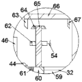
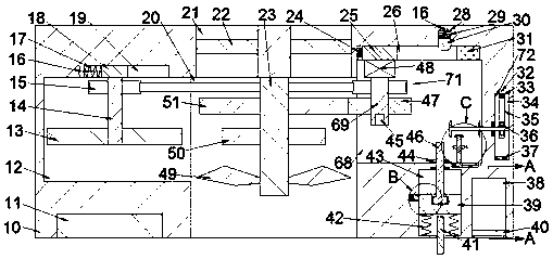
图1为本发明的一种服务器机房嵌入式散热装置的整体结构示意图;1 is a schematic diagram of the overall structure of an embedded cooling device in a server room according to the present invention;
图2为图1中A-A处结构示意图;Fig. 2 is the structural representation at A-A in Fig. 1;
图3为图1中B处结构示意图;Fig. 3 is the structural representation at B in Fig. 1;
图4为图1中C处结构示意图。FIG. 4 is a schematic diagram of the structure at C in FIG. 1 .
具体实施方式Detailed ways
下面结合附图说明和实施例对本发明作进一步说明,本发明的方式包括但不仅限于以下实施例。The present invention will be further described below with reference to the accompanying drawings and examples, and the modes of the present invention include but are not limited to the following examples.
如图1-4所示,一种服务器机房嵌入式散热装置,包括工作箱10以及位于所述工作箱10内且向上开口的环形吸风腔21,所述环形吸风腔21内固设有可将进入所述环形吸风腔21内的风进行过滤的环形滤板22,所述工作箱10内固设有位于所述环形吸风腔21下侧且与所述环形吸风腔21连通的第一空腔20,所述第一空腔20上侧内壁转动设有第一转轴23,所述第一转轴23上自上而下依次固设有第一齿轮51、第二齿轮50、吸风扇叶49,所述吸风扇叶49转动可将外界的风通过所述环形吸风腔21吸入室内,所述工作箱10内固设有可使所述第一转轴23以两种不同转速转动的差速转动装置71,所述工作箱10内固设有位于所述第一空腔20右侧的第二空腔43,所述第二空腔43内滑动设有活塞39,所述工作箱10下端面固设有位于所述第二空腔43下侧且向上延伸至所述第二空腔43内的导热杆41,所述导热杆41位于所述活塞39下侧,所述活塞39下侧的所述第二空腔43内充满热敏性气体,所述导热杆41可实时传递机房内的温度,所述工作箱10内固设有位于所述第二空腔43左侧且与所述第二空腔43连通的第一滑槽58,所述第一滑槽58内滑动设有第一圆形滑块56,所述第一圆形滑块56左端面与所述第一滑槽58左腔壁通过第一压缩弹簧57连接,所述工作箱10内固设有可发出报警的报警装置72,当所述活塞39向上滑动至与所述第二空腔43上侧内壁抵接时,所述报警装置72启动报警。As shown in Figures 1-4, an embedded cooling device in a server room includes a
有益地,所述差速转动装置71包括位于所述第一空腔20右侧且与所述第一空腔20连通的第三空腔68,所述工作箱10内固设有位于所述第三空腔68上侧且与所述第三空腔68连通的第二滑槽26,所述第二滑槽26右腔壁固设有电磁铁31,所述电磁铁31与所述第一圆形滑块56电信号连接,当所述第一圆形滑块56停止被挤压时,所述电磁铁31通电,所述第二滑槽26内滑动设有位于所述电磁铁31左侧的磁性滑块25,所述磁性滑块25左端面与所述第二滑槽26左腔壁通过第一拉伸弹簧24连接,所述磁性滑块25下端面固设有位于所述第三空腔68内的电机48,所述电机48下端面转动设有电机轴69,所述电机轴69内设有向下开口的键槽45,所述电机轴69上固设有与所述第一齿轮51啮合的第三齿轮47,所述工作箱10内固设有位于所述第二滑槽26上侧且与所述第二滑槽26连通的第三滑槽28,所述第三滑槽28内滑动设有部分位于所述第二滑槽26内的第二圆形滑块30,所述第二圆形滑块30上端面与所述第三滑槽28上侧内壁通过第二压缩弹簧29连接,当所述第三齿轮47与所述第一齿轮51啮合时,所述第一转轴23转速较慢。Beneficially, the
有益地,所述工作箱10内固设有位于所述第一空腔20左侧且与所述第一空腔20连通的第四空腔12,所述工作箱10内固设有位于所述第四空腔12上侧且与所述第四空腔12连通的第四滑槽19,所述第四滑槽19内滑动设有第一滑块18,所述第一滑块18左端面与所述第四滑槽19左腔壁通过第四滑槽19连接,所述第一滑块18左端面与所述第二圆形滑块30上端面通过第一拉绳16连接,所述第一滑块18下端面转动设有第四转轴14,所述第四转轴14上固定设有皮带轮15,所述电机轴69与所述第四转轴14通过所述皮带轮15传动连接,所述第四转轴14上且位于所述第二齿轮的左侧固定设有第四齿轮13,当所述第一拉绳16放松时,所述第一滑块18向右滑动至与所述第四滑槽19右腔壁抵接,所述第四齿轮13与所述第二齿轮50啮合,从而使所述第一转轴23以较快的转速转动,所述工作箱10内固设有位于所述第四空腔12下侧、所述第一空腔20左侧的冷凝器11,当所述电磁铁31通电时,所述冷凝器11启动排出冷气降温。Beneficially, a
有益地,所述工作箱10内固设有位于所述第二空腔43右侧且向下开口的第五空腔38,所述第五空腔38内装满灭火用的干粉,所述工作箱10内固设有位于所述第五空腔38后侧且与所述第五空腔38连通的第五滑槽52,所述第五滑槽52内滑动设有可封闭所述第五空腔38下口的封闭板40,所述封闭板40后端面与所述第五滑槽52后腔壁通过第三压缩弹簧53连接,所述工作箱10内固设有位于所述第三空腔68下侧且与所述第三空腔68连通的第六滑槽59,所述第六滑槽59内滑动设有第二滑块60,所述第二滑块60左端面与所述第六滑槽59左腔壁通过第二拉伸弹簧61连接,所述第二滑块60上端面转动设有位于所述第三空腔68内的第二转轴65,所述第二转轴65上固设有卷线轮62,所述卷线轮62与所述封闭板40后端面通过第二拉绳54连接,所述第二转轴65上固设有位于所述卷线轮62上侧的第一锥齿轮64,当所述卷线轮62转动时,向后拉动所述封闭板40,打开所述第五空腔38下口,从而使所述第五空腔38内的干粉落下,防止着火。Beneficially, a
有益地,所述报警装置72包括位于所述第三空腔68右侧的第六空腔34,所述第六空腔34右腔壁转动设有向左延伸至所述第三空腔68内的第三转轴66,所述第三转轴66上从右往左依次固设有位于所述第三空腔68内的第二锥齿轮67、第三锥齿轮63,所述第三转轴66上固设有位于所述第六空腔34内的第五齿轮36,所述第六空腔34后侧内壁滑动设有位于所述第五齿轮36后侧且与所述第五齿轮36啮合的齿条35,所述齿条35上端面与所述第六空腔34上侧内壁通过第三拉伸弹簧33连接,所述齿条35上端面与所述第二滑块60右端面通过第三拉绳32连接,所述第六空腔34下侧内壁固设有可报警的警报器37,当所述齿条35与所述警报器37抵接时,所述警报器37发出报警,所述第三拉绳32拉动所述第二滑块60向右滑动至与所述第六滑槽59右腔壁抵接,所述第一锥齿轮64与所述第二锥齿轮67啮合。Beneficially, the
有益地,所述活塞39内设有向上开口的T型腔55,所述T型腔55内转动设有向上延伸至所述第三空腔68内的T型转轴46,所述T型转轴46上固设有位于所述第三空腔68内的第四锥齿轮44,当所述活塞39向上滑动至与所述第二空腔43上侧内壁抵接时,所述T型转轴46卡入所述键槽45内,所述第四锥齿轮44与所述第三锥齿轮63啮合。Beneficially, the
整个装置的机械动作的顺序 :The sequence of mechanical actions of the whole device:
本发明的初始状态为:第一拉伸弹簧24为放松状态,电磁铁31未通电,第三齿轮47与第一齿轮51啮合,第二圆形滑块30部分位于第二滑槽26内,第二压缩弹簧29为放松状态,第一拉绳16为拉紧状态,第四压缩弹簧17为压缩状态,第四齿轮13与第二齿轮50未啮合,冷凝器11未启动,第四拉伸弹簧42为放松状态,第一压缩弹簧57为压缩状态,第一圆形滑块56位于第一滑槽58内,第四锥齿轮44与第三锥齿轮63未啮合,第一锥齿轮64与第二锥齿轮67未啮合,第三拉伸弹簧33为放松状态,第三拉绳32为放松状态,第二拉伸弹簧61为放松状态,第二拉绳54未拉紧,第三压缩弹簧53为放松状态,封闭板40封闭第五空腔38下口;The initial state of the present invention is: the
1.启动电机48带动电机轴69转动,电机轴69转动带动第三齿轮47转动,由于第三齿轮47与第一齿轮51啮合,第三齿轮47转动带动第一齿轮51转动,第一齿轮51转动带动第一转轴23转动,第一转轴23转动带动吸风扇叶49转动,吸风扇叶49转动将外界的风吸入环形吸风腔21内,经过环形滤板22过滤后通过第一空腔20吹出,对服务器机房进行散热降温;1. The
2.导热杆41实时监测服务器机房内的温度,将机房内的温度传递至第二空腔43内,使第二空腔43内的热敏性气体膨胀,若导热杆41监测到机房内的温度升高时,第二空腔43内的气体膨胀推动活塞39向上滑动,活塞39向上滑动拉伸第四拉伸弹簧42,当活塞39向上滑动至停止挤压第一圆形滑块56时,第一压缩弹簧57复位将第一圆形滑块56弹出,当第一圆形滑块56被顶出时,电磁铁31通电吸附磁性滑块25向右滑动,磁性滑块25向右滑动带动电机48向右滑动,电机48向右滑动带动电机轴69向右滑动,电机轴69向右滑动带动第三齿轮47向右滑动,从而使第三齿轮47与第一齿轮51脱离啮合;2. The heat conduction rod 41 monitors the temperature in the server room in real time, and transfers the temperature in the machine room to the
3.当电磁铁31通电时,冷凝器11启动对机房进行降温散热;3. When the electromagnet 31 is energized, the
4.当磁性滑块25向右滑动至与电磁铁31抵接时,挤压第二圆形滑块30向上滑入第三滑槽28内,挤压第二压缩弹簧29的同时使第一拉绳16放松,第一拉绳16放松从而使第四压缩弹簧17复位,第四压缩弹簧17复位使第一滑块18向右滑动,第一滑块18向右滑动带动第四转轴14向右滑动,第四转轴14向右滑动带动第四齿轮13向右滑动,当第一滑块18向右至与第四滑槽19右腔壁抵接时,第四齿轮13与第二齿轮50啮合,由于电机轴69与第四转轴14通过皮带轮15传动连接,电机轴69转动带动第四转轴14转动,第四转轴14转动带动第四齿轮13转动,第四齿轮13转动带动第二齿轮50转动,第二齿轮50转动带动第一转轴23以更快的转速转动,第一转轴23转动带动吸风扇叶49转动,吸风扇叶49转动增大进入环形吸风腔21内的风量,从而对机房内进行加速散热;4. When the
5.若机房内的温度继续升高,活塞39向上滑动至与第二空腔43上腔壁抵接时,T型转轴46卡入键槽45内,活塞39向上滑动带动T型转轴46向上滑动,T型转轴46向上滑动带动第四锥齿轮44向上滑动,第四锥齿轮44与第三锥齿轮63啮合,电机轴69转动带动T型转轴46转动,T型转轴46转动带动第四锥齿轮44转动,第四锥齿轮44转动带动第三锥齿轮63转动,第三锥齿轮63转动带动第三转轴66转动,第三转轴66转动带动第五齿轮36转动,由于第五齿轮36与齿条35上齿面啮合,第五齿轮36转动带动齿条35向下滑动,齿条35向下滑动拉紧第三拉绳32,第三拉绳32被拉紧拉动第二滑块60向右滑动,第二滑块60向右滑动带动第二转轴65向右滑动,当齿条35向下滑动至与警报器37抵接时,警报器37传出电信号发出报警;5. If the temperature in the machine room continues to rise, when the
6.当齿条35与警报器37抵接时,第二滑块60与第六滑槽59右腔壁抵接,第一锥齿轮64与第二锥齿轮67啮合,第三转轴66转动带动第二锥齿轮67转动,第二锥齿轮67转动带动第一锥齿轮64转动,第一锥齿轮64转动带动第二转轴65转动,第二转轴65转动带动卷线轮62转动,卷线轮62转动拉紧第二拉绳54,第二拉绳54被拉紧从而使封闭板40向后滑动,打开第五空腔38下口,使第五空腔38内的干粉落入机房内,防止机房内温度过高导致火灾,造成重大损失;6. When the
7.使用完成后,本发明恢复初始位置,继续对机房进行散热。7. After the use is completed, the present invention restores the original position and continues to dissipate heat in the machine room.
上述实施例只为说明本发明的技术构思及特点,其目的在于让熟悉此领域技术的人士能够了解本发明内容并加以实施,并不能以此限制本发明的保护范围。凡根据本发明精神实质所作的等效变化或修饰,都应涵盖在本发明的保护范围内。The above-mentioned embodiments are only intended to illustrate the technical concept and characteristics of the present invention, and the purpose thereof is to enable those skilled in the art to understand the content of the present invention and implement it, but not to limit the protection scope of the present invention. All equivalent changes or modifications made according to the spirit of the present invention should be covered within the protection scope of the present invention.
Claims (1)
Priority Applications (1)
| Application Number | Priority Date | Filing Date | Title |
|---|---|---|---|
| CN202010080860.6A CN111212552B (en) | 2020-02-05 | 2020-02-05 | An embedded cooling device in a server room |
Applications Claiming Priority (1)
| Application Number | Priority Date | Filing Date | Title |
|---|---|---|---|
| CN202010080860.6A CN111212552B (en) | 2020-02-05 | 2020-02-05 | An embedded cooling device in a server room |
Publications (2)
| Publication Number | Publication Date |
|---|---|
| CN111212552A CN111212552A (en) | 2020-05-29 |
| CN111212552B true CN111212552B (en) | 2020-09-08 |
Family
ID=70789908
Family Applications (1)
| Application Number | Title | Priority Date | Filing Date |
|---|---|---|---|
| CN202010080860.6A Expired - Fee Related CN111212552B (en) | 2020-02-05 | 2020-02-05 | An embedded cooling device in a server room |
Country Status (1)
| Country | Link |
|---|---|
| CN (1) | CN111212552B (en) |
Families Citing this family (5)
| Publication number | Priority date | Publication date | Assignee | Title |
|---|---|---|---|---|
| CN112135203B (en) * | 2020-09-14 | 2021-09-03 | 南京壹陆壹大数据科技有限公司 | Energy-concerving and environment-protective type network switch heat dissipation mechanism |
| CN112152122B (en) * | 2020-09-28 | 2021-06-15 | 广州市鼎隆机电安装有限公司 | A kind of electric equipment ventilation mechanism loading and unloading equipment |
| CN112178808B (en) * | 2020-10-20 | 2021-06-18 | 义乌市佳倩科技有限公司 | Dehumidification device capable of automatically adjusting dehumidification strength according to air humidity |
| CN114158218B (en) * | 2022-02-07 | 2022-04-19 | 山东万海电气科技有限公司 | Oil well frequency conversion cabinet with automatic inspection function |
| CN119353102B (en) * | 2024-12-25 | 2025-03-21 | 潍坊亚冠动力科技有限公司 | A containerized gas generator set |
Citations (8)
| Publication number | Priority date | Publication date | Assignee | Title |
|---|---|---|---|---|
| DE102007008594B4 (en) * | 2006-11-25 | 2011-06-09 | González de Mendoza, Adrián C. | Safety housing for protection of heat-emitting objects |
| CN108037807A (en) * | 2017-12-20 | 2018-05-15 | 苏州玛斯堡威电子科技有限公司 | A kind of server in machine room device of the collection of modified big data and processing |
| CN207766760U (en) * | 2018-01-03 | 2018-08-24 | 福建原动力信息技术有限公司 | A kind of radiator of network server computer room |
| CN207797286U (en) * | 2017-12-29 | 2018-08-31 | 重庆朗天通讯股份有限公司 | A kind of computer room temperature control system |
| CN108518095A (en) * | 2018-03-09 | 2018-09-11 | 深圳市律远汇智科技有限公司 | A kind of safe and reliable intelligent communication base station with automatic ventilation function |
| CN108613435A (en) * | 2018-05-16 | 2018-10-02 | 深圳汇呈环保科技有限公司 | A kind of high-efficient compressor and the refrigerating plant with it |
| CN109139148A (en) * | 2018-11-01 | 2019-01-04 | 钟莹莹 | A kind of steam turbine condenser and its operation method |
| CN110274346A (en) * | 2019-06-23 | 2019-09-24 | 安徽省华腾农业科技有限公司 | Multifunctional ventilation system |
Family Cites Families (1)
| Publication number | Priority date | Publication date | Assignee | Title |
|---|---|---|---|---|
| CA2911343A1 (en) * | 2014-11-06 | 2016-05-06 | Cinnos Technologies, Inc. | Smart mission critical rack |
-
2020
- 2020-02-05 CN CN202010080860.6A patent/CN111212552B/en not_active Expired - Fee Related
Patent Citations (8)
| Publication number | Priority date | Publication date | Assignee | Title |
|---|---|---|---|---|
| DE102007008594B4 (en) * | 2006-11-25 | 2011-06-09 | González de Mendoza, Adrián C. | Safety housing for protection of heat-emitting objects |
| CN108037807A (en) * | 2017-12-20 | 2018-05-15 | 苏州玛斯堡威电子科技有限公司 | A kind of server in machine room device of the collection of modified big data and processing |
| CN207797286U (en) * | 2017-12-29 | 2018-08-31 | 重庆朗天通讯股份有限公司 | A kind of computer room temperature control system |
| CN207766760U (en) * | 2018-01-03 | 2018-08-24 | 福建原动力信息技术有限公司 | A kind of radiator of network server computer room |
| CN108518095A (en) * | 2018-03-09 | 2018-09-11 | 深圳市律远汇智科技有限公司 | A kind of safe and reliable intelligent communication base station with automatic ventilation function |
| CN108613435A (en) * | 2018-05-16 | 2018-10-02 | 深圳汇呈环保科技有限公司 | A kind of high-efficient compressor and the refrigerating plant with it |
| CN109139148A (en) * | 2018-11-01 | 2019-01-04 | 钟莹莹 | A kind of steam turbine condenser and its operation method |
| CN110274346A (en) * | 2019-06-23 | 2019-09-24 | 安徽省华腾农业科技有限公司 | Multifunctional ventilation system |
Also Published As
| Publication number | Publication date |
|---|---|
| CN111212552A (en) | 2020-05-29 |
Similar Documents
| Publication | Publication Date | Title |
|---|---|---|
| CN111212552B (en) | An embedded cooling device in a server room | |
| CN110855065B (en) | High-efficient heat dissipation motor | |
| CN111555404B (en) | An anti-spontaneous combustion device for a heat-dissipating charging pile | |
| CN112103005A (en) | Communication cable | |
| CN111541290B (en) | A portable intelligent identification mobile phone charging treasure | |
| CN111049035B (en) | A distribution box with its own dust-proof and heat-dissipating device | |
| CN113721742A (en) | Heat dissipation dust collector of computer | |
| CN113784586A (en) | Anti-interference electronic communication filtering equipment and use method thereof | |
| CN111081288B (en) | A small database storage cabinet for emergency maintenance | |
| CN110049660A (en) | A kind of server in machine room device big data acquisition and handled | |
| CN110962559A (en) | Temperature adjustable device for power system of electric automobile | |
| CN214512429U (en) | Fire prevention fire-fighting equipment control box | |
| CN111009984B (en) | A protective cover that can automatically cool down the motor at high temperatures | |
| CN111397218A (en) | An external automatic power-off device for a water heater | |
| CN111162590A (en) | A mobile phone mobile power supply with support and cooling function | |
| CN112736589A (en) | Safety protection's intelligent plug | |
| CN102540668A (en) | Automatic cleaning projector dust screen device and projector | |
| CN113824964B (en) | Decoder for video monitoring | |
| CN211184087U (en) | A security monitoring device with good heat dissipation | |
| CN110112616B (en) | A terminal server device for information collection and management | |
| CN112576532A (en) | Automatic speed-regulating electronic cooling fan cleaning device | |
| CN218037877U (en) | A network server storage backup device | |
| CN114560046A (en) | Training equipment recycling platform for improving safety of underwater training | |
| CN216561707U (en) | VR all-in-one with novel heat dissipation air-out device | |
| CN214960772U (en) | Electric control device for curtain |
Legal Events
| Date | Code | Title | Description |
|---|---|---|---|
| PB01 | Publication | ||
| PB01 | Publication | ||
| SE01 | Entry into force of request for substantive examination | ||
| SE01 | Entry into force of request for substantive examination | ||
| TA01 | Transfer of patent application right |
Effective date of registration: 20200813 Address after: 518001 7a11, Jingze building, Shennan East Road, Luohu District, Shenzhen City, Guangdong Province Applicant after: Chen Shibin Address before: 318000 No. 25 Xiachen Street Center Street, Jiaojiang District, Taizhou City, Zhejiang Province Applicant before: Taizhou Jiaojiang Ruijiang Computer Co.,Ltd. |
|
| TA01 | Transfer of patent application right | ||
| GR01 | Patent grant | ||
| GR01 | Patent grant | ||
| TR01 | Transfer of patent right |
Effective date of registration: 20201124 Address after: Room 3b07, 3rd floor, Jingze building, Shennan East Road, Luohu District, Shenzhen City, Guangdong Province Patentee after: Shenzhen Guangshen Internet cloud computing Co.,Ltd. Address before: 518001 7a11, Jingze building, Shennan East Road, Luohu District, Shenzhen City, Guangdong Province Patentee before: Chen Shibin |
|
| TR01 | Transfer of patent right | ||
| CF01 | Termination of patent right due to non-payment of annual fee |
Granted publication date: 20200908 |
|
| CF01 | Termination of patent right due to non-payment of annual fee |