Disclosure of Invention
According to the defects of the prior art, the invention provides a strain measurement system and a strain measurement method for measuring the surface strain of a component, the strain measurement is carried out by utilizing the relation between the admittance and the strain of a single-feed degenerate orthogonal mode patch antenna, the effects of small size, high sensitivity and accurate measurement result of a strain sensor are realized, and the strain measurement system realizes wireless strain measurement and has good application prospect.
The technical scheme adopted by the invention for solving the technical problems is as follows:
on one hand, the invention provides a strain measurement system which comprises n single-feed degenerate orthomode patch antenna strain sensors, a radar system, a first horn antenna and a second horn antenna, wherein n is more than or equal to 1; the single-feed degenerate orthogonal mode patch antenna strain sensor is used for being stuck to different positions on a component to be measured, the single-feed degenerate orthogonal mode patch antenna strain sensor is a single-feed degenerate orthogonal mode patch antenna capable of generating a degenerate orthogonal mode, the single-feed degenerate orthogonal mode patch antenna strain sensor is in communication connection with a second horn antenna through a signal delay line, the signal delay line is used for transmitting sensing information of different strain sensor nodes and identifying the positions of the different strain sensor nodes in a sensing and measuring network system, the first horn antenna and the second horn antenna are aligned and are located on the same plane, and the first horn antenna is connected with a radar system through a cable.
According to the invention, the single-feed degenerate orthomode patch antenna and the radar scattering cross section detection technology are introduced into strain detection, and the magnitude and direction detection of structural strain is realized by using the adjacent orthomode theory of the antenna, so that a novel wireless strain detection method is provided for structural health monitoring.
Through first horn antenna and second horn antenna, realized the wireless transmission of detected signal, reduced the use of wire, avoided the complicated condition of on-the-spot wiring, simplified whole detecting system, practiced thrift the cost.
The single-feed patch antenna capable of generating the degenerate orthogonal mode excites two degenerate orthogonal modes TM10 and TM01 by using a degenerate separation unit, namely, an admittance curve graph of the antenna has two bimodal curves, and only two bimodal curves are arranged in the graph; compared with the prior art, the volume of the antenna used for the two-dimensional strain test is greatly reduced.
The degenerate separation unit is in the shape of a triangle, a groove, a rectangle and the like which are correspondingly formed after operations such as corner cutting, slotting, infinitesimal addition and the like are adopted on the basis of the square conductive patch. The single-feed degenerate orthogonal mode patch antenna sensor plays a role of a sensing unit, and when a structure to be tested generates strain and is transmitted to the single-feed degenerate orthogonal mode patch antenna strain sensor, the size of the single-feed degenerate orthogonal mode patch antenna sensor is changed, and the admittance of the single-feed degenerate orthogonal mode patch antenna sensor is changed.
Further, the single-feed degenerate orthogonal mode patch antenna strain sensor comprises a conductive patch, a dielectric substrate, a conductive ground plate, a transmission line and a quarter-wavelength impedance converter, wherein the conductive patch, the transmission line and the quarter-wavelength impedance converter are arranged on one surface of the dielectric substrate, the conductive patch is connected with the head end of the transmission line, the tail end of the transmission line is connected with the head end of the quarter-wavelength impedance converter, the tail end of the quarter-wavelength impedance converter is connected with one end of a signal delay line, the conductive ground plate is arranged on the other surface of the dielectric substrate, and the conductive ground plate is used for being stuck on the surface of a component to be tested.
Furthermore, the conductive patch is made of a copper foil material.
Furthermore, the conductive grounding plate is made of a copper foil material.
Further, the electrically conductive paster is the rectangle, the head end of transmission line and a right angle electric connection of rectangle, the transmission line is including the first section that is located the head end and the second section that is located the tail end, first section is 45 with the second section and buckles, the side of first section and rectangle all is 45 jiaos of settings.
Furthermore, the first horn antenna and the second horn antenna are arranged at a distance of 5-6 meters.
In another aspect, the present invention further provides a strain measurement method using the strain measurement system, including the following steps:
the method comprises the following steps that (1) n single-feed degenerate orthogonal mode patch antenna strain sensors are pasted on the surface of a component to be measured;
step (2), exciting the first horn antenna through the radar system to enable the first horn antenna to emit incident waves to the second horn antenna, receiving the incident waves by the second horn antenna to generate reflected waves, receiving the reflected waves by the first horn antenna and transmitting the reflected waves to the radar system, receiving the reflected waves by the radar system to process the signals, and accordingly deriving an antenna admittance curve graph, wherein an antenna admittance curve Y in the antenna admittance curve graph11The minimum value point between the two peaks is used as the strain measurement index Y of the single-feed degenerate orthogonal mode patch antenna after deformation along the directions of the x axis and the Y axissAccording to admittance curve Y11Whether the strain is generated in the x-direction or the Y-direction is inferred by the bimodal shift phenomenon of11The shift of the TM01 peak can be inferred as the strain in the x-direction, if the Y of the admittance curve is shifted11The shift of the TM10 peak can be used to infer that the strain is generated in the y direction;
and (3) the admittance of the single-feed degenerate orthogonal mode patch antenna strain sensor is related to the strain experienced by the strain sensor, the admittance curve of the single-feed degenerate orthogonal mode patch antenna is a bimodal curve, and a relational expression of the strain and the sensor admittance is constructed:
wherein: ε is the strain; y iss0The strain measurement index is the strain measurement index when the strain sensor does not experience strain; y issStrain measurement indexes of the strain sensor of the single-feed degenerate orthogonal mode patch antenna after strain; k is strain sensitivity; b is a coefficient;
step (4), strain measurement index Y of the strain sensor in the antenna admittance curve chart after strainsThe value is substituted into equation (1) to obtain the strain ε.
The invention has the following beneficial effects: (1) the single-feed patch antenna strain sensor capable of generating the degenerate orthogonal mode is adopted, so that the two-dimensional strain measurement of the component in the x and y directions is realized, and compared with the mode of utilizing an antenna array in the prior art, the strain sensor has smaller volume and is more convenient to apply practically; (2) the first horn antenna is excited by the radar system, the first horn antenna emits incident waves to the second horn antenna, the second horn antenna receives the incident waves and generates reflected waves, the radar system receives the reflected waves and performs signal processing on the reflected waves, wireless measurement of component strain is achieved, a large amount of wiring is not needed, and compared with the prior art, the wireless measurement device has the advantages that the flexibility is higher in practical application, and the structure is simpler; (3) the invention utilizes the characteristic that the admittance of the single-feed degenerate orthogonal mode patch antenna changes correspondingly when the single-feed degenerate orthogonal mode patch antenna is subjected to strain to establish the relationship between the strain and the admittance of the single-feed degenerate orthogonal mode patch antenna and measure the strain.
The first embodiment is as follows:
as shown in fig. 1 to 5, the strain measurement system provided by the present invention includes 1 single-feed degenerate orthogonal mode patch antenna strain sensor 6, a radar system 10, a first horn antenna 8, and a second horn antenna 9, in this embodiment, 1 single-feed degenerate orthogonal mode patch antenna strain sensor is used for strain measurement, and in practical applications, the strain measurement system may be a plurality of sensors; the strain sensor 6 of the single-feed degenerate orthogonal mode patch antenna is used for being pasted at different positions on a component 7 to be measured, the strain sensor 6 of the single-feed degenerate orthogonal mode patch antenna is a single-feed degenerate orthogonal mode patch antenna capable of generating a degenerate orthogonal mode, the strain sensor 6 of the single-feed degenerate orthogonal mode patch antenna is in communication connection with a second horn antenna 9 through a signal delay line 11, the signal delay line 11 is used for transmitting sensing information of different strain sensor nodes and identifying the positions of the different strain sensor nodes in a sensing measurement network system, each strain sensor node is a certain strain sensor 6 of the single-feed degenerate orthogonal mode patch antenna pasted on the component 7 to be measured, because each signal delay line 11 corresponds to different frequencies, the frequency ranges corresponding to the node numbers of the strain sensors are established in a one-to-one correspondence relationship, and the positions of the strain sensor nodes can be identified, the first horn antenna 8 and the second horn antenna 9 are aligned and located on the same plane, and the first horn antenna 8 is connected with the radar system 10 through a cable.
Through the first horn antenna 8 and the second horn antenna 9, wireless transmission of detection signals is realized, the use of wires is reduced, the situation of complex field wiring is avoided, the whole detection system is simplified, and the cost is saved;
according to the invention, the single-feed degenerate orthomode patch antenna and the radar scattering cross section detection technology are introduced into strain detection, and the magnitude and direction detection of structural strain is realized by using the adjacent orthomode theory of the antenna, so that a novel wireless strain detection method is provided for structural health monitoring.
The degenerate separation unit is in the shape of a triangle, a groove, a rectangle and the like which are correspondingly formed after operations such as corner cutting, slotting, infinitesimal addition and the like are adopted on the basis of the square conductive patch. The single-feed degenerate orthogonal mode patch antenna sensor plays a role of a sensing unit, and when a structure to be tested generates strain and is transmitted to the single-feed degenerate orthogonal mode patch antenna sensor, the size of the single-feed degenerate orthogonal mode patch antenna sensor is changed, and the admittance of the single-feed degenerate orthogonal mode patch antenna sensor is changed.
The single-feed patch antenna capable of generating the degenerate orthogonal mode excites two degenerate orthogonal modes TM10 and TM01 by using a degenerate separation unit, namely, an admittance curve graph of the antenna has two bimodal curves, and only two bimodal curves are arranged in the graph; compared with the prior art, the volume of the antenna used for the two-dimensional strain test is greatly reduced, and the antenna has a good application prospect.
Further, the single-feed degenerate orthogonal mode patch antenna strain sensor comprises a conductive patch 1, a dielectric substrate 2, a conductive ground plate 3, a transmission line 4 and a quarter-wavelength impedance converter 5, wherein the conductive patch 1, the transmission line 4 and the quarter-wavelength impedance converter 5 are arranged on one surface of the dielectric substrate 2, the conductive patch 1 is connected with the head end of the transmission line 4, the tail end of the transmission line 4 is connected with the head end of the quarter-wavelength impedance converter 5, the tail end of the quarter-wavelength impedance converter 5 is connected with one end of a signal delay line 11, the conductive ground plate 3 is arranged on the other surface of the dielectric substrate 2, and the conductive ground plate 3 is used for being adhered to the surface of a component 7 to be measured to measure the strain of the component.
Further, the conductive patch 1 is made of copper foil.
Further, the conductive ground plate 3 is made of copper foil.
Further, the conductive patch 1 is rectangular, the rectangular conductive patch 1 is a rectangular degenerate separation unit formed by adding infinitesimal elements on the basis of a square conductive patch and is used for exciting two degenerate orthogonal modes TM10 and TM01, the head end of the transmission line 4 is electrically connected with a right angle of the rectangle, the transmission line 4 comprises a first section located at the head end and a second section located at the tail end, the first section and the second section are bent at 45 degrees, and the sides of the first section and the rectangle are arranged at 45 degrees.
Further, the first horn antenna 8 and the second horn antenna 9 are arranged at a distance of 5-6 meters. Effectively realize the wireless detection of meeting an emergency, simplified monitoring system, increased the convenience of system setup.
A strain measurement method using the strain measurement system comprises the following steps:
step (1), a single-feed degenerate orthogonal mode patch antenna strain sensor 6 is pasted on the surface of a component to be tested 7, and only one single-feed degenerate orthogonal mode patch antenna strain sensor 6 is selected for verification in the embodiment, as shown in fig. 12; in the actual test, a plurality of strain sensors can be arranged to be attached to the component 7 to be tested as required, as shown in fig. 4;
step (2), the first horn antenna 8 is excited through the radar system 10, so that the first horn antenna 8 emits incident waves to the second horn antenna 9, the second horn antenna 9 receives the incident waves to generate reflected waves, the first horn antenna 8 receives the reflected waves and transmits the reflected waves to the radar system 10, the radar system 10 receives the reflected waves to process the signals, an antenna admittance curve graph is deduced, and an admittance curve Y in the graph is obtained11To infer thatWhether the variation occurs in the x-or Y-direction, if Y of the admittance curve11The shift of the TM01 peak can be inferred as the strain in the x-direction, if the Y of the admittance curve is shifted11The shift of the TM10 peak can be used to infer that the strain is generated in the y direction;
the x and y directions in which strain occurs are related to the position of the strain sensor as already noted in fig. 2 and 4.
And (3) taking a minimum value point of an antenna admittance curve Y11 in the antenna admittance curve graph as a strain measurement index Ys (the minimum value point is the minimum value point between two peaks) of the single-feed degenerate orthogonal mode patch antenna after deformation along the directions of the x axis and the Y axis.
Under the strain-free condition (namely, the strain is 0 mu epsilon), the strain sensor obtains an admittance curve Y11-0, a reference value Ys0 of a strain measurement index obtained from the curve Y11-0 is 0.01668S (the value is a minimum value point between two peaks of a Y11-0 curve), and the system stores the value of the reference value Ys0 so as to directly call the reference value in subsequent measurement. When the strain sensor is subjected to the strain with the x direction of 453.1 mu epsilon, the system performs signal processing to obtain an admittance curve Y11-1, and a strain measurement index Ys1 in the curve Y11-1 is 0.01745S; when the strain sensor is subjected to strain with the x direction of 902.0 mu epsilon, the system performs signal processing to obtain an admittance curve Y11-2, and a strain measurement index Ys2 in the curve Y11-2 is 0.01832S; when the strain sensor is subjected to the strain with the x direction of 1342.0 mu epsilon, the system carries out signal processing to obtain an admittance curve Y11-3, and the strain measurement index Ys3 in the curve Y11-3 is 0.01917S. Four admittance curves Y11-0, Y11-1, Y11-2, Y11-3 corresponding to four strain levels of 0 μ ∈, 453.1 μ ∈, 902.0 μ ∈, 1342.0 μ ∈ are plotted in the same graph, as shown in fig. 6.
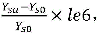
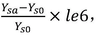
Ys0(0.01668S) under the non-strain condition is used as a reference value of the strain measurement indexes under other strain conditions, and the strain measurement indexes Ys1, Ys2 and Ys3 under three strain levels of 453.1 mu epsilon, 902.0 mu epsilon and 1342.0 mu epsilon are respectively subjected to standardization treatment, namely
a takes 1, 2 and 3, and the same method is continued to give the X directionThe strain measurement indexes of 5 groups of strains can be more, and the strain measurement indexes are standardized, so that a series of standardized admittance minimum values are obtained, the standardized admittance minimum values and the strains are subjected to data fitting to obtain a fitting curve as shown in fig. 7, then the data fitting is carried out to obtain that the strain sensitivity (namely the slope of a connecting line in fig. 7) in the x direction is 116.2 ppm/mu epsilon, the fitting goodness of the fitting curve is 0.9934, and the standard deviation is 42.39 mu epsilon, and the strain sensitivity of 1 ppm/mu epsilon can only be obtained by adopting a method of taking the resonance frequency as the strain index in the prior antenna strain sensor technology. Therefore, the sensitivity of the antenna strain sensor provided by the invention is far higher than that of the prior art which adopts resonant frequency for testing.
It can also be seen from the admittance plot of fig. 6 that as the strain increases in the x-direction, the TM01 peak of the admittance curve shifts to the left with respect to the unstrained state, and the greater the strain, the more pronounced the shift to the left.
In order to eliminate the interference of the test environment and the manufacturing process difference of different strain gauges, the measurement index of the strain sensor under the non-strain condition needs to be calibrated again every time a test is carried out, wherein the strain sensor obtains an admittance curve Y11-0 under the non-strain condition (namely, the strain is 0 mu epsilon), a reference value Ys0 of the strain measurement index obtained from the curve Y11-0 is 0.01668S (the value is the minimum value point between two peaks of the Y11-0 curve), and the system stores the value of the reference value Ys0 so as to directly call the reference value in the subsequent measurement. When the strain sensor is subjected to strain with the Y direction of 453.1 mu epsilon, the system performs signal processing to obtain an admittance curve Y11-4, and a strain measurement index Ys4 in the curve Y11-4 is 0.01589S; when the strain sensor is subjected to strain with the Y direction of 902.0 mu epsilon, the system performs signal processing to obtain an admittance curve Y11-5, and a strain measurement index Ys5 in the curve Y11-5 is 0.01519S; when the strain sensor experiences the strain with the Y direction of 1342.0 mu epsilon, the system carries out signal processing to obtain an admittance curve Y11-6, and the strain measurement index Ys6 from the curve Y11-6 is 0.01455S. Four admittance curves Y11-0, Y11-4, Y11-5, Y11-6 corresponding to four strain levels of 0, 453.1, 902.0, 1342.0 μ ∈ are plotted in the same graph, as shown in fig. 8. And 453.1. 902.0, 1342.0 mu epsilon strain measurement indexes Ys4, Ys5 and Ys6 under three strain grades are standardized, namely
a takes 4, 5 and 6, 5 groups of strain in the y direction are continuously provided by the same method, or more strain measurement indexes are taken and standardized, so that a series of standardized admittance minimum values are obtained, data fitting is carried out on the standardized admittance minimum values and the strain to obtain a fitting curve as shown in figure 9, then data fitting is carried out to obtain the strain sensitivity in the y direction of-92.06 ppm/mu epsilon, the fitting goodness of the fitting curve is 0.9975, the standard deviation is 29.62 mu epsilon, and the method adopting the resonance frequency as the strain index in the prior antenna strain sensor technology can only obtain the strain sensitivity of 1 ppm/mu epsilon. The sensitivity of the antenna strain sensor provided by the invention is far higher than that of the antenna strain sensor adopting resonant frequency for testing in the prior art.
It can also be seen from the admittance plot of fig. 8 that as the strain increases in the y-direction, the TM10 peak of the admittance curve shifts to the left with respect to the unstrained state, and the greater the strain, the more pronounced the shift to the left.
The admittance of the strain sensor of the single-feed degenerate orthogonal mode patch antenna is related to the strain experienced by the strain sensor, the admittance curve of the single-feed degenerate orthogonal mode patch antenna is a double-peak curve, and a relational expression of the strain and the minimum value point of the sensor admittance is constructed:
wherein: ε is the strain; y iss0The strain measurement index is the strain measurement index when the strain sensor does not experience strain; y issStrain measurement indexes of the strain sensor of the single-feed degenerate orthogonal mode patch antenna after strain; k is strain sensitivity; b is a coefficient; the sensitivity k and the coefficient b in the formula 2 have different values of strain in the x direction and strain in the y direction.
When the strain sensor experiences strain in the x direction, k is 116.2 ppm/. mu.epsilon.and b is-6677 ppm (as can be obtained from FIG. 7), the specific expression of the relationship between the strain in the x direction and the minimum point of the sensor admittance is as follows:
when the strain sensor experiences y-direction strain, k is-92.06 ppm/. mu.epsilon.and b is-3937 ppm (as can be seen from FIG. 9), the specific expression for the relationship between the y-direction strain and the minimum point of the sensor admittance is as follows:
step (4), strain measurement index Y of the strain sensor in the antenna admittance curve chart after strainsSubstituting the value into a formula (3) or (4) to obtain the strain epsilon, and selecting the formula to carry in after judging whether the strain is in the x direction or the y direction according to the deviation rule of the admittance curve.
In the embodiment, a strain 1126.8 mu epsilon in the x direction is applied to the strain sensor of the single-feed degenerate orthogonal mode patch antenna to verify the effectiveness of the system, and the strain measurement index Ys7 obtained after the system is subjected to signal processing is 0.01875S. Firstly, according to the admittance chart (fig. 10), the TM01 peak can be seen to shift to the left relative to the unstrained state, and the strain can be judged to occur in the x direction; then, substituting Ys7 into equation (3) calculates the strain magnitude to be 1125.45. mu. epsilon. Therefore, after the admittance curve chart is judged and the system is applied to test and calculation, the difference between the input strain and the input strain is 1.35 mu epsilon, the allowable range is obtained, the direction judgment is correct, and the test accuracy of the system is high.
In the embodiment, a strain 1126.8 mu epsilon in the y direction is applied to the strain sensor of the single-feed degenerate orthogonal mode patch antenna to verify the effectiveness of the system, and the strain measurement index Ys8 obtained after the system is subjected to signal processing is 0.01487S. Firstly, according to the obvious leftward shift of the peak of an admittance curve chart TM10 relative to an admittance curve without strain, judging that the strain occurs in the y direction; then, substituting Ys8 into equation (4) calculates the strain magnitude to be 1135.96. mu. epsilon. Therefore, after the system is judged through the admittance curve chart and is used for testing and calculating, the difference between the input strain and the input strain is 9.16 mu epsilon, the allowable range is obtained, the direction judgment is correct, and the testing accuracy of the system is high.
The single-feed degenerate orthogonal mode patch antenna strain sensor capable of generating the degenerate orthogonal mode is adopted, so that two-dimensional strain measurement of the component in the x and y directions is realized, and compared with a mode of utilizing an antenna array in the prior art, the two-dimensional strain sensor has smaller volume and is more convenient to apply practically; the first horn antenna is excited by the radar system, the first horn antenna emits incident waves to the second horn antenna, the second horn antenna receives the incident waves and generates reflected waves, the radar system receives the reflected waves and performs signal processing on the reflected waves, wireless measurement of component strain is achieved, a large amount of wiring is not needed, and compared with the prior art, the wireless measurement device has the advantages that the flexibility is higher in practical application, and the structure is simpler; the invention utilizes the characteristic that the admittance of the single-feed degenerate orthogonal mode patch antenna changes correspondingly when the single-feed degenerate orthogonal mode patch antenna is subjected to strain to establish the relationship between the strain and the admittance of the single-feed degenerate orthogonal mode patch antenna and measure the strain.
The above description is an embodiment of the present invention, and not intended to limit the scope of the present invention, and all modifications, equivalents, and flow changes made by using the contents of the present specification and drawings, or applied directly or indirectly to other related technical fields are included in the scope of the present invention.


