CN111194199B - Elastic laminate with curved elastic member and method of manufacturing the same - Google Patents
Elastic laminate with curved elastic member and method of manufacturing the same Download PDFInfo
- Publication number
- CN111194199B CN111194199B CN201880065779.1A CN201880065779A CN111194199B CN 111194199 B CN111194199 B CN 111194199B CN 201880065779 A CN201880065779 A CN 201880065779A CN 111194199 B CN111194199 B CN 111194199B
- Authority
- CN
- China
- Prior art keywords
- bonds
- bond
- area
- elastomeric
- strands
- Prior art date
- Legal status (The legal status is an assumption and is not a legal conclusion. Google has not performed a legal analysis and makes no representation as to the accuracy of the status listed.)
- Active
Links
Images


Classifications
-
- B—PERFORMING OPERATIONS; TRANSPORTING
- B32—LAYERED PRODUCTS
- B32B—LAYERED PRODUCTS, i.e. PRODUCTS BUILT-UP OF STRATA OF FLAT OR NON-FLAT, e.g. CELLULAR OR HONEYCOMB, FORM
- B32B7/00—Layered products characterised by the relation between layers; Layered products characterised by the relative orientation of features between layers, or by the relative values of a measurable parameter between layers, i.e. products comprising layers having different physical, chemical or physicochemical properties; Layered products characterised by the interconnection of layers
- B32B7/04—Interconnection of layers
- B32B7/08—Interconnection of layers by mechanical means
- B32B7/09—Interconnection of layers by mechanical means by stitching, needling or sewing
-
- B—PERFORMING OPERATIONS; TRANSPORTING
- B32—LAYERED PRODUCTS
- B32B—LAYERED PRODUCTS, i.e. PRODUCTS BUILT-UP OF STRATA OF FLAT OR NON-FLAT, e.g. CELLULAR OR HONEYCOMB, FORM
- B32B37/00—Methods or apparatus for laminating, e.g. by curing or by ultrasonic bonding
- B32B37/12—Methods or apparatus for laminating, e.g. by curing or by ultrasonic bonding characterised by using adhesives
- B32B37/1284—Application of adhesive
- B32B37/1292—Application of adhesive selectively, e.g. in stripes, in patterns
-
- A—HUMAN NECESSITIES
- A61—MEDICAL OR VETERINARY SCIENCE; HYGIENE
- A61F—FILTERS IMPLANTABLE INTO BLOOD VESSELS; PROSTHESES; DEVICES PROVIDING PATENCY TO, OR PREVENTING COLLAPSING OF, TUBULAR STRUCTURES OF THE BODY, e.g. STENTS; ORTHOPAEDIC, NURSING OR CONTRACEPTIVE DEVICES; FOMENTATION; TREATMENT OR PROTECTION OF EYES OR EARS; BANDAGES, DRESSINGS OR ABSORBENT PADS; FIRST-AID KITS
- A61F13/00—Bandages or dressings; Absorbent pads
- A61F13/15—Absorbent pads, e.g. sanitary towels, swabs or tampons for external or internal application to the body; Supporting or fastening means therefor; Tampon applicators
- A61F13/15577—Apparatus or processes for manufacturing
- A61F13/15585—Apparatus or processes for manufacturing of babies' napkins, e.g. diapers
- A61F13/15593—Apparatus or processes for manufacturing of babies' napkins, e.g. diapers having elastic ribbons fixed thereto; Devices for applying the ribbons
-
- A—HUMAN NECESSITIES
- A61—MEDICAL OR VETERINARY SCIENCE; HYGIENE
- A61F—FILTERS IMPLANTABLE INTO BLOOD VESSELS; PROSTHESES; DEVICES PROVIDING PATENCY TO, OR PREVENTING COLLAPSING OF, TUBULAR STRUCTURES OF THE BODY, e.g. STENTS; ORTHOPAEDIC, NURSING OR CONTRACEPTIVE DEVICES; FOMENTATION; TREATMENT OR PROTECTION OF EYES OR EARS; BANDAGES, DRESSINGS OR ABSORBENT PADS; FIRST-AID KITS
- A61F13/00—Bandages or dressings; Absorbent pads
- A61F13/15—Absorbent pads, e.g. sanitary towels, swabs or tampons for external or internal application to the body; Supporting or fastening means therefor; Tampon applicators
- A61F13/15577—Apparatus or processes for manufacturing
- A61F13/15699—Forming webs by bringing together several webs, e.g. by laminating or folding several webs, with or without additional treatment of the webs
-
- A—HUMAN NECESSITIES
- A61—MEDICAL OR VETERINARY SCIENCE; HYGIENE
- A61F—FILTERS IMPLANTABLE INTO BLOOD VESSELS; PROSTHESES; DEVICES PROVIDING PATENCY TO, OR PREVENTING COLLAPSING OF, TUBULAR STRUCTURES OF THE BODY, e.g. STENTS; ORTHOPAEDIC, NURSING OR CONTRACEPTIVE DEVICES; FOMENTATION; TREATMENT OR PROTECTION OF EYES OR EARS; BANDAGES, DRESSINGS OR ABSORBENT PADS; FIRST-AID KITS
- A61F13/00—Bandages or dressings; Absorbent pads
- A61F13/15—Absorbent pads, e.g. sanitary towels, swabs or tampons for external or internal application to the body; Supporting or fastening means therefor; Tampon applicators
- A61F13/45—Absorbent pads, e.g. sanitary towels, swabs or tampons for external or internal application to the body; Supporting or fastening means therefor; Tampon applicators characterised by the shape
- A61F13/49—Absorbent articles specially adapted to be worn around the waist, e.g. diapers
- A61F13/49007—Form-fitting, self-adjusting disposable diapers
- A61F13/49009—Form-fitting, self-adjusting disposable diapers with elastic means
- A61F13/4902—Form-fitting, self-adjusting disposable diapers with elastic means characterised by the elastic material
-
- B—PERFORMING OPERATIONS; TRANSPORTING
- B32—LAYERED PRODUCTS
- B32B—LAYERED PRODUCTS, i.e. PRODUCTS BUILT-UP OF STRATA OF FLAT OR NON-FLAT, e.g. CELLULAR OR HONEYCOMB, FORM
- B32B25/00—Layered products comprising a layer of natural or synthetic rubber
- B32B25/04—Layered products comprising a layer of natural or synthetic rubber comprising rubber as the main or only constituent of a layer, which is next to another layer of the same or of a different material
- B32B25/042—Layered products comprising a layer of natural or synthetic rubber comprising rubber as the main or only constituent of a layer, which is next to another layer of the same or of a different material of natural rubber or synthetic rubber
-
- B—PERFORMING OPERATIONS; TRANSPORTING
- B32—LAYERED PRODUCTS
- B32B—LAYERED PRODUCTS, i.e. PRODUCTS BUILT-UP OF STRATA OF FLAT OR NON-FLAT, e.g. CELLULAR OR HONEYCOMB, FORM
- B32B25/00—Layered products comprising a layer of natural or synthetic rubber
- B32B25/04—Layered products comprising a layer of natural or synthetic rubber comprising rubber as the main or only constituent of a layer, which is next to another layer of the same or of a different material
- B32B25/045—Layered products comprising a layer of natural or synthetic rubber comprising rubber as the main or only constituent of a layer, which is next to another layer of the same or of a different material of foam
-
- B—PERFORMING OPERATIONS; TRANSPORTING
- B32—LAYERED PRODUCTS
- B32B—LAYERED PRODUCTS, i.e. PRODUCTS BUILT-UP OF STRATA OF FLAT OR NON-FLAT, e.g. CELLULAR OR HONEYCOMB, FORM
- B32B25/00—Layered products comprising a layer of natural or synthetic rubber
- B32B25/04—Layered products comprising a layer of natural or synthetic rubber comprising rubber as the main or only constituent of a layer, which is next to another layer of the same or of a different material
- B32B25/08—Layered products comprising a layer of natural or synthetic rubber comprising rubber as the main or only constituent of a layer, which is next to another layer of the same or of a different material of synthetic resin
-
- B—PERFORMING OPERATIONS; TRANSPORTING
- B32—LAYERED PRODUCTS
- B32B—LAYERED PRODUCTS, i.e. PRODUCTS BUILT-UP OF STRATA OF FLAT OR NON-FLAT, e.g. CELLULAR OR HONEYCOMB, FORM
- B32B25/00—Layered products comprising a layer of natural or synthetic rubber
- B32B25/10—Layered products comprising a layer of natural or synthetic rubber next to a fibrous or filamentary layer
-
- B—PERFORMING OPERATIONS; TRANSPORTING
- B32—LAYERED PRODUCTS
- B32B—LAYERED PRODUCTS, i.e. PRODUCTS BUILT-UP OF STRATA OF FLAT OR NON-FLAT, e.g. CELLULAR OR HONEYCOMB, FORM
- B32B25/00—Layered products comprising a layer of natural or synthetic rubber
- B32B25/14—Layered products comprising a layer of natural or synthetic rubber comprising synthetic rubber copolymers
-
- B—PERFORMING OPERATIONS; TRANSPORTING
- B32—LAYERED PRODUCTS
- B32B—LAYERED PRODUCTS, i.e. PRODUCTS BUILT-UP OF STRATA OF FLAT OR NON-FLAT, e.g. CELLULAR OR HONEYCOMB, FORM
- B32B25/00—Layered products comprising a layer of natural or synthetic rubber
- B32B25/16—Layered products comprising a layer of natural or synthetic rubber comprising polydienes homopolymers or poly-halodienes homopolymers
-
- B—PERFORMING OPERATIONS; TRANSPORTING
- B32—LAYERED PRODUCTS
- B32B—LAYERED PRODUCTS, i.e. PRODUCTS BUILT-UP OF STRATA OF FLAT OR NON-FLAT, e.g. CELLULAR OR HONEYCOMB, FORM
- B32B27/00—Layered products comprising a layer of synthetic resin
-
- B—PERFORMING OPERATIONS; TRANSPORTING
- B32—LAYERED PRODUCTS
- B32B—LAYERED PRODUCTS, i.e. PRODUCTS BUILT-UP OF STRATA OF FLAT OR NON-FLAT, e.g. CELLULAR OR HONEYCOMB, FORM
- B32B27/00—Layered products comprising a layer of synthetic resin
- B32B27/06—Layered products comprising a layer of synthetic resin as the main or only constituent of a layer, which is next to another layer of the same or of a different material
- B32B27/065—Layered products comprising a layer of synthetic resin as the main or only constituent of a layer, which is next to another layer of the same or of a different material of foam
-
- B—PERFORMING OPERATIONS; TRANSPORTING
- B32—LAYERED PRODUCTS
- B32B—LAYERED PRODUCTS, i.e. PRODUCTS BUILT-UP OF STRATA OF FLAT OR NON-FLAT, e.g. CELLULAR OR HONEYCOMB, FORM
- B32B27/00—Layered products comprising a layer of synthetic resin
- B32B27/06—Layered products comprising a layer of synthetic resin as the main or only constituent of a layer, which is next to another layer of the same or of a different material
- B32B27/08—Layered products comprising a layer of synthetic resin as the main or only constituent of a layer, which is next to another layer of the same or of a different material of synthetic resin
-
- B—PERFORMING OPERATIONS; TRANSPORTING
- B32—LAYERED PRODUCTS
- B32B—LAYERED PRODUCTS, i.e. PRODUCTS BUILT-UP OF STRATA OF FLAT OR NON-FLAT, e.g. CELLULAR OR HONEYCOMB, FORM
- B32B27/00—Layered products comprising a layer of synthetic resin
- B32B27/12—Layered products comprising a layer of synthetic resin next to a fibrous or filamentary layer
-
- B—PERFORMING OPERATIONS; TRANSPORTING
- B32—LAYERED PRODUCTS
- B32B—LAYERED PRODUCTS, i.e. PRODUCTS BUILT-UP OF STRATA OF FLAT OR NON-FLAT, e.g. CELLULAR OR HONEYCOMB, FORM
- B32B3/00—Layered products comprising a layer with external or internal discontinuities or unevennesses, or a layer of non-planar form; Layered products having particular features of form
- B32B3/02—Layered products comprising a layer with external or internal discontinuities or unevennesses, or a layer of non-planar form; Layered products having particular features of form characterised by features of form at particular places, e.g. in edge regions
- B32B3/04—Layered products comprising a layer with external or internal discontinuities or unevennesses, or a layer of non-planar form; Layered products having particular features of form characterised by features of form at particular places, e.g. in edge regions characterised by at least one layer folded at the edge, e.g. over another layer ; characterised by at least one layer enveloping or enclosing a material
-
- B—PERFORMING OPERATIONS; TRANSPORTING
- B32—LAYERED PRODUCTS
- B32B—LAYERED PRODUCTS, i.e. PRODUCTS BUILT-UP OF STRATA OF FLAT OR NON-FLAT, e.g. CELLULAR OR HONEYCOMB, FORM
- B32B3/00—Layered products comprising a layer with external or internal discontinuities or unevennesses, or a layer of non-planar form; Layered products having particular features of form
- B32B3/10—Layered products comprising a layer with external or internal discontinuities or unevennesses, or a layer of non-planar form; Layered products having particular features of form characterised by a discontinuous layer, i.e. formed of separate pieces of material
- B32B3/18—Layered products comprising a layer with external or internal discontinuities or unevennesses, or a layer of non-planar form; Layered products having particular features of form characterised by a discontinuous layer, i.e. formed of separate pieces of material characterised by an internal layer formed of separate pieces of material which are juxtaposed side-by-side
- B32B3/20—Layered products comprising a layer with external or internal discontinuities or unevennesses, or a layer of non-planar form; Layered products having particular features of form characterised by a discontinuous layer, i.e. formed of separate pieces of material characterised by an internal layer formed of separate pieces of material which are juxtaposed side-by-side of hollow pieces, e.g. tubes; of pieces with channels or cavities
-
- B—PERFORMING OPERATIONS; TRANSPORTING
- B32—LAYERED PRODUCTS
- B32B—LAYERED PRODUCTS, i.e. PRODUCTS BUILT-UP OF STRATA OF FLAT OR NON-FLAT, e.g. CELLULAR OR HONEYCOMB, FORM
- B32B3/00—Layered products comprising a layer with external or internal discontinuities or unevennesses, or a layer of non-planar form; Layered products having particular features of form
- B32B3/26—Layered products comprising a layer with external or internal discontinuities or unevennesses, or a layer of non-planar form; Layered products having particular features of form characterised by a particular shape of the outline of the cross-section of a continuous layer; characterised by a layer with cavities or internal voids ; characterised by an apertured layer
- B32B3/266—Layered products comprising a layer with external or internal discontinuities or unevennesses, or a layer of non-planar form; Layered products having particular features of form characterised by a particular shape of the outline of the cross-section of a continuous layer; characterised by a layer with cavities or internal voids ; characterised by an apertured layer characterised by an apertured layer, the apertures going through the whole thickness of the layer, e.g. expanded metal, perforated layer, slit layer regular cells B32B3/12
-
- B—PERFORMING OPERATIONS; TRANSPORTING
- B32—LAYERED PRODUCTS
- B32B—LAYERED PRODUCTS, i.e. PRODUCTS BUILT-UP OF STRATA OF FLAT OR NON-FLAT, e.g. CELLULAR OR HONEYCOMB, FORM
- B32B3/00—Layered products comprising a layer with external or internal discontinuities or unevennesses, or a layer of non-planar form; Layered products having particular features of form
- B32B3/26—Layered products comprising a layer with external or internal discontinuities or unevennesses, or a layer of non-planar form; Layered products having particular features of form characterised by a particular shape of the outline of the cross-section of a continuous layer; characterised by a layer with cavities or internal voids ; characterised by an apertured layer
- B32B3/28—Layered products comprising a layer with external or internal discontinuities or unevennesses, or a layer of non-planar form; Layered products having particular features of form characterised by a particular shape of the outline of the cross-section of a continuous layer; characterised by a layer with cavities or internal voids ; characterised by an apertured layer characterised by a layer comprising a deformed thin sheet, i.e. the layer having its entire thickness deformed out of the plane, e.g. corrugated, crumpled
-
- B—PERFORMING OPERATIONS; TRANSPORTING
- B32—LAYERED PRODUCTS
- B32B—LAYERED PRODUCTS, i.e. PRODUCTS BUILT-UP OF STRATA OF FLAT OR NON-FLAT, e.g. CELLULAR OR HONEYCOMB, FORM
- B32B3/00—Layered products comprising a layer with external or internal discontinuities or unevennesses, or a layer of non-planar form; Layered products having particular features of form
- B32B3/26—Layered products comprising a layer with external or internal discontinuities or unevennesses, or a layer of non-planar form; Layered products having particular features of form characterised by a particular shape of the outline of the cross-section of a continuous layer; characterised by a layer with cavities or internal voids ; characterised by an apertured layer
- B32B3/30—Layered products comprising a layer with external or internal discontinuities or unevennesses, or a layer of non-planar form; Layered products having particular features of form characterised by a particular shape of the outline of the cross-section of a continuous layer; characterised by a layer with cavities or internal voids ; characterised by an apertured layer characterised by a layer formed with recesses or projections, e.g. hollows, grooves, protuberances, ribs
-
- B—PERFORMING OPERATIONS; TRANSPORTING
- B32—LAYERED PRODUCTS
- B32B—LAYERED PRODUCTS, i.e. PRODUCTS BUILT-UP OF STRATA OF FLAT OR NON-FLAT, e.g. CELLULAR OR HONEYCOMB, FORM
- B32B37/00—Methods or apparatus for laminating, e.g. by curing or by ultrasonic bonding
- B32B37/0076—Methods or apparatus for laminating, e.g. by curing or by ultrasonic bonding characterised in that the layers are not bonded on the totality of their surfaces
- B32B37/0084—Point bonding
-
- B—PERFORMING OPERATIONS; TRANSPORTING
- B32—LAYERED PRODUCTS
- B32B—LAYERED PRODUCTS, i.e. PRODUCTS BUILT-UP OF STRATA OF FLAT OR NON-FLAT, e.g. CELLULAR OR HONEYCOMB, FORM
- B32B37/00—Methods or apparatus for laminating, e.g. by curing or by ultrasonic bonding
- B32B37/10—Methods or apparatus for laminating, e.g. by curing or by ultrasonic bonding characterised by the pressing technique, e.g. using action of vacuum or fluid pressure
-
- B—PERFORMING OPERATIONS; TRANSPORTING
- B32—LAYERED PRODUCTS
- B32B—LAYERED PRODUCTS, i.e. PRODUCTS BUILT-UP OF STRATA OF FLAT OR NON-FLAT, e.g. CELLULAR OR HONEYCOMB, FORM
- B32B37/00—Methods or apparatus for laminating, e.g. by curing or by ultrasonic bonding
- B32B37/12—Methods or apparatus for laminating, e.g. by curing or by ultrasonic bonding characterised by using adhesives
-
- B—PERFORMING OPERATIONS; TRANSPORTING
- B32—LAYERED PRODUCTS
- B32B—LAYERED PRODUCTS, i.e. PRODUCTS BUILT-UP OF STRATA OF FLAT OR NON-FLAT, e.g. CELLULAR OR HONEYCOMB, FORM
- B32B37/00—Methods or apparatus for laminating, e.g. by curing or by ultrasonic bonding
- B32B37/14—Methods or apparatus for laminating, e.g. by curing or by ultrasonic bonding characterised by the properties of the layers
- B32B37/144—Methods or apparatus for laminating, e.g. by curing or by ultrasonic bonding characterised by the properties of the layers using layers with different mechanical or chemical conditions or properties, e.g. layers with different thermal shrinkage, layers under tension during bonding
-
- B—PERFORMING OPERATIONS; TRANSPORTING
- B32—LAYERED PRODUCTS
- B32B—LAYERED PRODUCTS, i.e. PRODUCTS BUILT-UP OF STRATA OF FLAT OR NON-FLAT, e.g. CELLULAR OR HONEYCOMB, FORM
- B32B37/00—Methods or apparatus for laminating, e.g. by curing or by ultrasonic bonding
- B32B37/14—Methods or apparatus for laminating, e.g. by curing or by ultrasonic bonding characterised by the properties of the layers
- B32B37/16—Methods or apparatus for laminating, e.g. by curing or by ultrasonic bonding characterised by the properties of the layers with all layers existing as coherent layers before laminating
- B32B37/18—Methods or apparatus for laminating, e.g. by curing or by ultrasonic bonding characterised by the properties of the layers with all layers existing as coherent layers before laminating involving the assembly of discrete sheets or panels only
- B32B37/182—Methods or apparatus for laminating, e.g. by curing or by ultrasonic bonding characterised by the properties of the layers with all layers existing as coherent layers before laminating involving the assembly of discrete sheets or panels only one or more of the layers being plastic
- B32B37/185—Laminating sheets, panels or inserts between two discrete plastic layers
-
- B—PERFORMING OPERATIONS; TRANSPORTING
- B32—LAYERED PRODUCTS
- B32B—LAYERED PRODUCTS, i.e. PRODUCTS BUILT-UP OF STRATA OF FLAT OR NON-FLAT, e.g. CELLULAR OR HONEYCOMB, FORM
- B32B5/00—Layered products characterised by the non- homogeneity or physical structure, i.e. comprising a fibrous, filamentary, particulate or foam layer; Layered products characterised by having a layer differing constitutionally or physically in different parts
- B32B5/02—Layered products characterised by the non- homogeneity or physical structure, i.e. comprising a fibrous, filamentary, particulate or foam layer; Layered products characterised by having a layer differing constitutionally or physically in different parts characterised by structural features of a fibrous or filamentary layer
- B32B5/022—Non-woven fabric
-
- B—PERFORMING OPERATIONS; TRANSPORTING
- B32—LAYERED PRODUCTS
- B32B—LAYERED PRODUCTS, i.e. PRODUCTS BUILT-UP OF STRATA OF FLAT OR NON-FLAT, e.g. CELLULAR OR HONEYCOMB, FORM
- B32B5/00—Layered products characterised by the non- homogeneity or physical structure, i.e. comprising a fibrous, filamentary, particulate or foam layer; Layered products characterised by having a layer differing constitutionally or physically in different parts
- B32B5/02—Layered products characterised by the non- homogeneity or physical structure, i.e. comprising a fibrous, filamentary, particulate or foam layer; Layered products characterised by having a layer differing constitutionally or physically in different parts characterised by structural features of a fibrous or filamentary layer
- B32B5/024—Woven fabric
-
- B—PERFORMING OPERATIONS; TRANSPORTING
- B32—LAYERED PRODUCTS
- B32B—LAYERED PRODUCTS, i.e. PRODUCTS BUILT-UP OF STRATA OF FLAT OR NON-FLAT, e.g. CELLULAR OR HONEYCOMB, FORM
- B32B5/00—Layered products characterised by the non- homogeneity or physical structure, i.e. comprising a fibrous, filamentary, particulate or foam layer; Layered products characterised by having a layer differing constitutionally or physically in different parts
- B32B5/02—Layered products characterised by the non- homogeneity or physical structure, i.e. comprising a fibrous, filamentary, particulate or foam layer; Layered products characterised by having a layer differing constitutionally or physically in different parts characterised by structural features of a fibrous or filamentary layer
- B32B5/08—Layered products characterised by the non- homogeneity or physical structure, i.e. comprising a fibrous, filamentary, particulate or foam layer; Layered products characterised by having a layer differing constitutionally or physically in different parts characterised by structural features of a fibrous or filamentary layer the fibres or filaments of a layer being of different substances, e.g. conjugate fibres, mixture of different fibres
-
- B—PERFORMING OPERATIONS; TRANSPORTING
- B32—LAYERED PRODUCTS
- B32B—LAYERED PRODUCTS, i.e. PRODUCTS BUILT-UP OF STRATA OF FLAT OR NON-FLAT, e.g. CELLULAR OR HONEYCOMB, FORM
- B32B5/00—Layered products characterised by the non- homogeneity or physical structure, i.e. comprising a fibrous, filamentary, particulate or foam layer; Layered products characterised by having a layer differing constitutionally or physically in different parts
- B32B5/18—Layered products characterised by the non- homogeneity or physical structure, i.e. comprising a fibrous, filamentary, particulate or foam layer; Layered products characterised by having a layer differing constitutionally or physically in different parts characterised by features of a layer of foamed material
-
- B—PERFORMING OPERATIONS; TRANSPORTING
- B32—LAYERED PRODUCTS
- B32B—LAYERED PRODUCTS, i.e. PRODUCTS BUILT-UP OF STRATA OF FLAT OR NON-FLAT, e.g. CELLULAR OR HONEYCOMB, FORM
- B32B5/00—Layered products characterised by the non- homogeneity or physical structure, i.e. comprising a fibrous, filamentary, particulate or foam layer; Layered products characterised by having a layer differing constitutionally or physically in different parts
- B32B5/22—Layered products characterised by the non- homogeneity or physical structure, i.e. comprising a fibrous, filamentary, particulate or foam layer; Layered products characterised by having a layer differing constitutionally or physically in different parts characterised by the presence of two or more layers which are next to each other and are fibrous, filamentary, formed of particles or foamed
- B32B5/24—Layered products characterised by the non- homogeneity or physical structure, i.e. comprising a fibrous, filamentary, particulate or foam layer; Layered products characterised by having a layer differing constitutionally or physically in different parts characterised by the presence of two or more layers which are next to each other and are fibrous, filamentary, formed of particles or foamed one layer being a fibrous or filamentary layer
- B32B5/245—Layered products characterised by the non- homogeneity or physical structure, i.e. comprising a fibrous, filamentary, particulate or foam layer; Layered products characterised by having a layer differing constitutionally or physically in different parts characterised by the presence of two or more layers which are next to each other and are fibrous, filamentary, formed of particles or foamed one layer being a fibrous or filamentary layer another layer next to it being a foam layer
-
- B—PERFORMING OPERATIONS; TRANSPORTING
- B32—LAYERED PRODUCTS
- B32B—LAYERED PRODUCTS, i.e. PRODUCTS BUILT-UP OF STRATA OF FLAT OR NON-FLAT, e.g. CELLULAR OR HONEYCOMB, FORM
- B32B5/00—Layered products characterised by the non- homogeneity or physical structure, i.e. comprising a fibrous, filamentary, particulate or foam layer; Layered products characterised by having a layer differing constitutionally or physically in different parts
- B32B5/22—Layered products characterised by the non- homogeneity or physical structure, i.e. comprising a fibrous, filamentary, particulate or foam layer; Layered products characterised by having a layer differing constitutionally or physically in different parts characterised by the presence of two or more layers which are next to each other and are fibrous, filamentary, formed of particles or foamed
- B32B5/24—Layered products characterised by the non- homogeneity or physical structure, i.e. comprising a fibrous, filamentary, particulate or foam layer; Layered products characterised by having a layer differing constitutionally or physically in different parts characterised by the presence of two or more layers which are next to each other and are fibrous, filamentary, formed of particles or foamed one layer being a fibrous or filamentary layer
- B32B5/26—Layered products characterised by the non- homogeneity or physical structure, i.e. comprising a fibrous, filamentary, particulate or foam layer; Layered products characterised by having a layer differing constitutionally or physically in different parts characterised by the presence of two or more layers which are next to each other and are fibrous, filamentary, formed of particles or foamed one layer being a fibrous or filamentary layer another layer next to it also being fibrous or filamentary
-
- B—PERFORMING OPERATIONS; TRANSPORTING
- B32—LAYERED PRODUCTS
- B32B—LAYERED PRODUCTS, i.e. PRODUCTS BUILT-UP OF STRATA OF FLAT OR NON-FLAT, e.g. CELLULAR OR HONEYCOMB, FORM
- B32B5/00—Layered products characterised by the non- homogeneity or physical structure, i.e. comprising a fibrous, filamentary, particulate or foam layer; Layered products characterised by having a layer differing constitutionally or physically in different parts
- B32B5/22—Layered products characterised by the non- homogeneity or physical structure, i.e. comprising a fibrous, filamentary, particulate or foam layer; Layered products characterised by having a layer differing constitutionally or physically in different parts characterised by the presence of two or more layers which are next to each other and are fibrous, filamentary, formed of particles or foamed
- B32B5/32—Layered products characterised by the non- homogeneity or physical structure, i.e. comprising a fibrous, filamentary, particulate or foam layer; Layered products characterised by having a layer differing constitutionally or physically in different parts characterised by the presence of two or more layers which are next to each other and are fibrous, filamentary, formed of particles or foamed at least two layers being foamed and next to each other
-
- B—PERFORMING OPERATIONS; TRANSPORTING
- B32—LAYERED PRODUCTS
- B32B—LAYERED PRODUCTS, i.e. PRODUCTS BUILT-UP OF STRATA OF FLAT OR NON-FLAT, e.g. CELLULAR OR HONEYCOMB, FORM
- B32B2262/00—Composition or structural features of fibres which form a fibrous or filamentary layer or are present as additives
- B32B2262/02—Synthetic macromolecular fibres
- B32B2262/0253—Polyolefin fibres
-
- B—PERFORMING OPERATIONS; TRANSPORTING
- B32—LAYERED PRODUCTS
- B32B—LAYERED PRODUCTS, i.e. PRODUCTS BUILT-UP OF STRATA OF FLAT OR NON-FLAT, e.g. CELLULAR OR HONEYCOMB, FORM
- B32B2262/00—Composition or structural features of fibres which form a fibrous or filamentary layer or are present as additives
- B32B2262/02—Synthetic macromolecular fibres
- B32B2262/0261—Polyamide fibres
-
- B—PERFORMING OPERATIONS; TRANSPORTING
- B32—LAYERED PRODUCTS
- B32B—LAYERED PRODUCTS, i.e. PRODUCTS BUILT-UP OF STRATA OF FLAT OR NON-FLAT, e.g. CELLULAR OR HONEYCOMB, FORM
- B32B2262/00—Composition or structural features of fibres which form a fibrous or filamentary layer or are present as additives
- B32B2262/02—Synthetic macromolecular fibres
- B32B2262/0276—Polyester fibres
-
- B—PERFORMING OPERATIONS; TRANSPORTING
- B32—LAYERED PRODUCTS
- B32B—LAYERED PRODUCTS, i.e. PRODUCTS BUILT-UP OF STRATA OF FLAT OR NON-FLAT, e.g. CELLULAR OR HONEYCOMB, FORM
- B32B2262/00—Composition or structural features of fibres which form a fibrous or filamentary layer or are present as additives
- B32B2262/04—Cellulosic plastic fibres, e.g. rayon
-
- B—PERFORMING OPERATIONS; TRANSPORTING
- B32—LAYERED PRODUCTS
- B32B—LAYERED PRODUCTS, i.e. PRODUCTS BUILT-UP OF STRATA OF FLAT OR NON-FLAT, e.g. CELLULAR OR HONEYCOMB, FORM
- B32B2262/00—Composition or structural features of fibres which form a fibrous or filamentary layer or are present as additives
- B32B2262/06—Vegetal fibres
- B32B2262/062—Cellulose fibres, e.g. cotton
- B32B2262/067—Wood fibres
-
- B—PERFORMING OPERATIONS; TRANSPORTING
- B32—LAYERED PRODUCTS
- B32B—LAYERED PRODUCTS, i.e. PRODUCTS BUILT-UP OF STRATA OF FLAT OR NON-FLAT, e.g. CELLULAR OR HONEYCOMB, FORM
- B32B2262/00—Composition or structural features of fibres which form a fibrous or filamentary layer or are present as additives
- B32B2262/12—Conjugate fibres, e.g. core/sheath or side-by-side
-
- B—PERFORMING OPERATIONS; TRANSPORTING
- B32—LAYERED PRODUCTS
- B32B—LAYERED PRODUCTS, i.e. PRODUCTS BUILT-UP OF STRATA OF FLAT OR NON-FLAT, e.g. CELLULAR OR HONEYCOMB, FORM
- B32B2262/00—Composition or structural features of fibres which form a fibrous or filamentary layer or are present as additives
- B32B2262/14—Mixture of at least two fibres made of different materials
-
- B—PERFORMING OPERATIONS; TRANSPORTING
- B32—LAYERED PRODUCTS
- B32B—LAYERED PRODUCTS, i.e. PRODUCTS BUILT-UP OF STRATA OF FLAT OR NON-FLAT, e.g. CELLULAR OR HONEYCOMB, FORM
- B32B2270/00—Resin or rubber layer containing a blend of at least two different polymers
-
- B—PERFORMING OPERATIONS; TRANSPORTING
- B32—LAYERED PRODUCTS
- B32B—LAYERED PRODUCTS, i.e. PRODUCTS BUILT-UP OF STRATA OF FLAT OR NON-FLAT, e.g. CELLULAR OR HONEYCOMB, FORM
- B32B2307/00—Properties of the layers or laminate
- B32B2307/50—Properties of the layers or laminate having particular mechanical properties
- B32B2307/51—Elastic
-
- B—PERFORMING OPERATIONS; TRANSPORTING
- B32—LAYERED PRODUCTS
- B32B—LAYERED PRODUCTS, i.e. PRODUCTS BUILT-UP OF STRATA OF FLAT OR NON-FLAT, e.g. CELLULAR OR HONEYCOMB, FORM
- B32B2307/00—Properties of the layers or laminate
- B32B2307/70—Other properties
- B32B2307/718—Weight, e.g. weight per square meter
-
- B—PERFORMING OPERATIONS; TRANSPORTING
- B32—LAYERED PRODUCTS
- B32B—LAYERED PRODUCTS, i.e. PRODUCTS BUILT-UP OF STRATA OF FLAT OR NON-FLAT, e.g. CELLULAR OR HONEYCOMB, FORM
- B32B2307/00—Properties of the layers or laminate
- B32B2307/70—Other properties
- B32B2307/726—Permeability to liquids, absorption
- B32B2307/7265—Non-permeable
-
- B—PERFORMING OPERATIONS; TRANSPORTING
- B32—LAYERED PRODUCTS
- B32B—LAYERED PRODUCTS, i.e. PRODUCTS BUILT-UP OF STRATA OF FLAT OR NON-FLAT, e.g. CELLULAR OR HONEYCOMB, FORM
- B32B2307/00—Properties of the layers or laminate
- B32B2307/70—Other properties
- B32B2307/728—Hydrophilic
-
- B—PERFORMING OPERATIONS; TRANSPORTING
- B32—LAYERED PRODUCTS
- B32B—LAYERED PRODUCTS, i.e. PRODUCTS BUILT-UP OF STRATA OF FLAT OR NON-FLAT, e.g. CELLULAR OR HONEYCOMB, FORM
- B32B2307/00—Properties of the layers or laminate
- B32B2307/70—Other properties
- B32B2307/73—Hydrophobic
-
- B—PERFORMING OPERATIONS; TRANSPORTING
- B32—LAYERED PRODUCTS
- B32B—LAYERED PRODUCTS, i.e. PRODUCTS BUILT-UP OF STRATA OF FLAT OR NON-FLAT, e.g. CELLULAR OR HONEYCOMB, FORM
- B32B2437/00—Clothing
-
- B—PERFORMING OPERATIONS; TRANSPORTING
- B32—LAYERED PRODUCTS
- B32B—LAYERED PRODUCTS, i.e. PRODUCTS BUILT-UP OF STRATA OF FLAT OR NON-FLAT, e.g. CELLULAR OR HONEYCOMB, FORM
- B32B2535/00—Medical equipment, e.g. bandage, prostheses, catheter
-
- B—PERFORMING OPERATIONS; TRANSPORTING
- B32—LAYERED PRODUCTS
- B32B—LAYERED PRODUCTS, i.e. PRODUCTS BUILT-UP OF STRATA OF FLAT OR NON-FLAT, e.g. CELLULAR OR HONEYCOMB, FORM
- B32B2555/00—Personal care
- B32B2555/02—Diapers or napkins
-
- B—PERFORMING OPERATIONS; TRANSPORTING
- B32—LAYERED PRODUCTS
- B32B—LAYERED PRODUCTS, i.e. PRODUCTS BUILT-UP OF STRATA OF FLAT OR NON-FLAT, e.g. CELLULAR OR HONEYCOMB, FORM
- B32B37/00—Methods or apparatus for laminating, e.g. by curing or by ultrasonic bonding
- B32B37/04—Methods or apparatus for laminating, e.g. by curing or by ultrasonic bonding characterised by the partial melting of at least one layer
Abstract
The invention discloses an elasticized material and an article comprising an elasticized material. In one embodiment, an elasticized material may comprise a first layer, a second layer, elastomeric strands disposed between the first layer and the second layer, and a plurality of bonds bonding the first layer and the second layer together. The strands may have straight portions and arcuate portions. The bonds may include a first bond and a second bond, and may be disposed on opposite sides of the strand and spaced apart by a distance less than an untensioned diameter of the strand. The first bonds and the second bonds may be disposed along straight portions of the strands. The plurality of bonds may also include third bonds and fourth bonds longitudinally adjacent and disposed on opposite sides of the strand and spaced apart by a distance greater than the untensioned diameter of the strand. The third bond and the fourth bond may be disposed along strand arcuate portions.
Description
Priority requirement
This application claims priority from U.S. provisional application No.62/579,546 entitled "Elastic textiles With Curved elastomers And Methods For Manufacturing" filed on 31.10.2017 And U.S. provisional application No.62/579,494 entitled "Elastic textiles With Curved elastomers And Methods For Manufacturing" filed on 31.10.2017, the contents of which are hereby incorporated by reference in a manner consistent With this application.
Technical Field
The present disclosure relates to elasticized materials, and more particularly to elasticized materials having curved elastomeric strands.
Background
Elasticized materials are used in many different applications, including in various garments and absorbent articles. Such elasticized materials may be used as part of a waistband, leg cuffs, barrier cuffs, or in other components of garments and absorbent articles to provide beneficial fit properties, to help prevent body exudates from leaking out, or to impart other benefits.
Many current garments and absorbent articles include elasticized materials comprising elastomeric strands positioned between and adhesively secured to material layers. Some prior art elasticized materials attempt to remove the adhesive to facilitate securing the elastomeric strands to the material layer by using discrete, separate bonds. These prior art materials locate bonds across the elastomeric strands a distance less than the untensioned diameter of the elastomeric strands. Some exemplary prior art materials can be found in U.S. Pat. No.6,291,039 to Cera France Compleginie d' Equipment Robotique application, entitled "Ruffling Slide and Method for Making Same". This particular structural arrangement holds the elastomeric strands between bonds within the elasticized material. These adhesive-free elasticized materials have a cost advantage in that they do not require adhesive to secure the elastomeric strands within the elasticized material. It has been found that forming an elasticized material with curved elastomeric strands in this manner is problematic because bending the elastomeric strands during the manufacture of such elasticized material can result in the formation of bonds through the elastomeric strands, thereby breaking or otherwise damaging the elastomeric strands. Accordingly, it is desirable to include an elasticized material that does not include a binder and that includes bent elastomeric strands and does not suffer from strand breakage, and methods of forming the elasticized material.
Disclosure of Invention
The present disclosure relates to elasticized materials, and more particularly to elasticized materials having curved elastomeric strands. Generally, the elasticized material of the present disclosure is configured without adhesive and comprises elastomeric strands forming a generally arcuate or curved shape. Forming an elasticized material without the use of adhesives provides a significant cost advantage in reducing the amount of adhesive used in the garment of an absorbent article and in the associated machinery required for adhesive application. The lack of adhesive also has advantages related to product benefits such as increased softness and unique visible patterns due to the discrete bonds. Arcuate or curved elastomeric strands may provide better fit control.
In one embodiment, an elasticized material may comprise a first substrate layer, a second substrate layer, elastomeric strands disposed between the first substrate layer and the second substrate layer, and a plurality of bonds bonding the first substrate layer to the second substrate layer. The elastomeric strands may include at least one straight portion and at least one arcuate portion. The plurality of bonds may include at least a first bond and a second bond, which may be disposed on opposite sides of the elastomeric strand and separated by a distance less than the untensioned diameter of the elastomeric strand, and may also be disposed along at least one straight portion of the elastomeric strand. The plurality of bonds may also include at least a third bond and a fourth bond, which may be adjacent in the machine direction and disposed on opposite sides of the elastomeric strand and spaced apart by a distance greater than the untensioned diameter of the elastomeric strand, and may also be disposed along at least one arcuate portion of the elastomeric strand.
In another embodiment, an elasticized material extending in a cross direction and a machine direction may comprise a first web of material, a second web of material bonded to the first web of material by a plurality of bonds, and elastomeric strands extending in the cross direction and disposed between the first web of material and the second web of material. The material may also include a first transverse area comprising a plurality of pairs of bonds, and the bonds within each of the plurality of pairs of bonds may be spaced apart in the longitudinal direction by a distance less than the untensioned diameter of the elastomeric strand, and a second transverse area comprising a plurality of bonds, wherein a majority of longitudinally adjacent bonds of the plurality of bonds within the second transverse area may be spaced apart from each other in the longitudinal direction by a distance greater than the untensioned diameter of the elastomeric strand. The elastomeric strands may extend between the plurality of bond pairs of the first transverse area and may extend through the second transverse area in an arcuate manner.
In another embodiment, an elasticized material may comprise a first substrate layer, a second substrate layer, elastomeric strands disposed between the first substrate layer and the second substrate layer, and a plurality of bonds bonding the first substrate layer to the second substrate layer. The elastomeric strands may include at least one straight portion and at least one arcuate portion. The elastomeric strands may be secured in place between the first and second substrate layers along at least one straight portion and may move between the first and second substrate layers along at least one arcuate portion.
The above summary of the present disclosure is not intended to describe each embodiment or every implementation of the present disclosure. Advantages and attainments, together with a more complete understanding of the disclosure, will become apparent and appreciated by referring to the following detailed description and claims taken in conjunction with the accompanying drawings.
Drawings
The disclosure may be more completely understood in consideration of the following detailed description of various embodiments in connection with the accompanying drawings, in which:
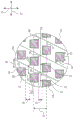
FIG. 1 is a plan view of an elasticized material according to aspects of the present disclosure;
FIG. 2 is a close-up plan view of a portion of the elasticized material of FIG. 1;
FIG. 3 is a plan view of another elasticated material in accordance with aspects of the present disclosure;
FIG. 4 is a close-up plan view of a portion of the elasticized material of FIG. 3;
FIG. 5 is a plan view of another elasticated material in accordance with aspects of the present disclosure;
FIG. 6 is a close-up plan view of a portion of the elasticized material of FIG. 5;
FIG. 7 is a schematic illustration of a process for forming the elasticized material of the present disclosure;
FIG. 8 is a schematic illustration of another process for forming the elasticized material of the present disclosure;
FIG. 9 is a plan view of an exemplary absorbent article including an elasticized material, according to aspects of the present invention;
FIG. 10 is a plan view of another exemplary absorbent article including an elasticized material, according to aspects of the present disclosure; and is
Fig. 11 is a schematic illustration of a process for forming an absorbent article including curved elastomeric strands, according to aspects of the present disclosure.
While the disclosure is susceptible to various modifications and alternative forms, specifics thereof have been shown by way of example in the drawings and will be described in detail. It should be understood, however, that the intention is not to limit aspects of the disclosure to the particular embodiments described. On the contrary, the intention is to cover all modifications, equivalents, and alternatives falling within the scope of the disclosure.
Detailed Description
The present disclosure relates generally to elasticized materials and processes for forming elasticized materials with arcuate or curved elastomeric strands. Generally, the elasticized material may not require an adhesive to secure the elastomeric strands within the material. It should be understood, however, that in some embodiments, the elasticized materials disclosed herein may also benefit from the application of an adhesive. For example, the elasticized material may employ a laminating adhesive to ensure consistent contact and minimal slippage between the materials of the elasticized material. The present disclosure details many different material structures that can be formed by the process using different bonding patterns to secure elastomeric strands in an arcuate or curved shape within an elasticized material.
Each example is given by way of illustration and is not meant as a limitation. For example, features illustrated or described as part of one embodiment or figure can be used on another embodiment or figure to yield a still further embodiment. It is intended that the present disclosure encompass such modifications and variations.
Although some suitable dimensions, ranges, and/or values are disclosed in connection with various components, features, and/or specifications, it will be understood by those skilled in the art to which the disclosure relates that desired dimensions, ranges, and/or values may deviate from those explicitly disclosed.
When introducing elements of the present disclosure or the preferred embodiments thereof, the articles "a," "an," "the," and "said" are intended to mean that there are one or more of the elements. The terms "comprising," "including," and "having" are intended to be inclusive and mean that there may be additional elements other than the listed elements. Many modifications and variations of this disclosure can be made without departing from its spirit and scope. Accordingly, the above exemplary embodiments should not be used to limit the scope of the present invention.
Defining:
the term "absorbent article" refers herein to articles that can be placed against or in proximity to (i.e., adjacent to) the body of the wearer to absorb and contain the various liquid, solid, and semi-solid exudates discharged from the body. Such absorbent articles as described herein are intended to be discarded after a limited period of use rather than being laundered or otherwise restored for reuse. It is understood that the present disclosure is applicable to a variety of disposable absorbent articles, including, but not limited to, diapers, pant diapers, training pants, swim pants, feminine hygiene products (including, but not limited to, catamenial pads or panties), incontinence products, adult diapers and pants, medical garments, surgical pads and bandages, other personal care or health care garments, and the like, without departing from the scope of the present disclosure.
The terms "bonded," "attached," or "coupled" herein refer to the joining, adhering, connecting, attaching, or the like, of two elements. Two elements will be considered to be bonded, attached, or coupled together when they are joined, adhered, connected, attached, or the like, either directly to each other or to each other, such as when each element is directly bonded to intermediate elements. The bonding, attachment or coupling of one element to another element may be by continuous or intermittent bonding.
The term "carded web" refers herein to webs that contain natural or synthetic tuft length (staple length) fibers having a fiber length of typically less than about 100 mm. The bundle of tufted fibers may be subjected to an opening process to separate the fibers, then the fibers are sent to a carding process, where the fibers are separated and carded to align them in the machine direction, after which the fibers are deposited on a moving wire for further processing. Such webs typically undergo some sort of bonding process, such as thermal bonding using heat and/or pressure. Additionally or alternatively, the fibers may be subjected to an adhesion process to bond the fibers together, for example, by using a powder adhesive. The carded web may undergo fluid entanglement, such as hydroentanglement, to further entangle the fibers and thereby improve the integrity of the carded web. Because the fibers are aligned in the machine direction, the carded web, once bonded, typically has a machine direction strength (machine direction strength) that is greater than the cross machine direction strength (cross machine direction strength).
The term "film" refers herein to a thermoplastic film made using an extrusion and/or shaping process such as a cast film or blown film extrusion process. The term includes apertured films, slit films, and other porous films that constitute liquid transfer films, as well as films that do not transfer liquid, such as, but not limited to, barrier films, filled films, breathable films, and oriented films.
The term "gsm" refers herein to grams per square meter.
The term "hydrophilic" refers herein to fibers or fiber surfaces that are wetted by aqueous liquids in contact with the fibers. The degree of wetting of a material can in turn be described in terms of the contact angles and surface tensions of the liquids and materials involved. Apparatus and techniques suitable for measuring the wettability of a particular fibrous material or blend of fibrous materials can be provided by a Cahn SFA-222 Surface Force analysis System (Cahn SFA-222 Surface Force Analyzer System) or a substantially equivalent System. Fibers having contact angles less than 90 are considered "wettable" or hydrophilic and fibers having contact angles greater than 90 are considered "nonwettable" or hydrophobic when measured using this system.
The term "meltblown" refers herein to fibers formed by extruding a molten thermoplastic material through a plurality of fine, usually circular, die capillaries as molten threads or filaments into converging high velocity heated gas (e.g. air) streams which attenuate the filaments of molten thermoplastic material to reduce their diameter, which may be to microfiber diameter. Thereafter, the meltblown fibers are carried by the high velocity gas stream and are deposited on a collecting surface to form a web of randomly dispersed meltblown fibers. Such a process is disclosed, for example, in U.S. patent No. 3,849,241 to Butin et al, which is incorporated herein by reference. Meltblown fibers are microfibers which may be continuous or discontinuous, are generally smaller than about 0.6 denier, and may be tacky and self-adhering when deposited onto a collecting surface.
The term "nonwoven" refers herein to a material or web of material that is formed without the aid of a fabric weaving or knitting process. The material or web of material may have a structure of individual fibers, filaments or threads (collectively "fibers"), which may be intercalated (interlaid), but in a manner different from that recognizable in a knitted fabric. The nonwoven material or web may be formed from a number of processes such as, but not limited to, meltblowing processes, spunbonding processes, carded web processes, hydroentanglement processes, and the like.
The term "spunbond" refers herein to the extrusion of molten thermoplastic material as filaments from a plurality of fine capillaries of a spinneret having a circular or other configuration through small diameter fibers formed by drawing and then rapidly reducing the diameter of the extruded filaments by conventional processes such as drawing and the processes described in U.S. patent No. 4,340,563 to Appel et al, U.S. patent No. 3,692,618 to Dorschner et al, U.S. patent No. 3,802,817 to Matsuki et al, U.S. patent nos. 3,338,992 and 3,341,394 to Kinney, U.S. patent No. 3,502,763 to Hartmann, U.S. patent No. 3,502,538 to terpeson, and U.S. patent No. 3,542,615 to Dobo et al, each of which is incorporated herein by reference in its entirety. Spunbond fibers are substantially continuous and typically have an average denier of greater than about 0.3, and in one embodiment between about 0.6, 5, and 10 and about 15, 20, and 40. Spunbond fibers generally do not become tacky when they are deposited onto a collecting surface.
The term "elasticized," when used herein to describe a portion of a material or article, means that the material or article is made from a non-elastic sheet material coupled to an elastomeric material, such as one or more elastomeric bands or strands, such that the material or article exhibits elastic properties.
The term "thermoplastic" refers herein to a material that softens and sets when exposed to heat and which substantially returns to a non-softened condition when cooled.
The term "user" or "caregiver" refers herein to a person: which fit an absorbent article, such as, but not limited to, a diaper, pant diaper, training pant, jumbo pants, incontinence product, or other absorbent article, around the wearer of one of these absorbent articles. The user and the wearer may be the same person.
An elasticizing material:
fig. 1 is a top plan view depicting a portion of an exemplary elasticized material 10. The elasticated material 10 extends generally in a longitudinal direction 31 and a transverse direction 32 between the top sheet edge 11 and the bottom sheet edge 13. The elasticized material 10 may generally comprise a first layer of material 12, a second layer of material 14, elastomeric strands 16, and bonds 20. As will be described in greater detail below, at least some of the bonds 20 may be positioned on opposite sides of the elastomeric strands 16 in such a manner that the bonds 20 secure or "trap" portions of the elastomeric strands 16 in place within the elasticized material 10.
Figure 3A depicts a close-up view of the circle 33 of figure 1 depicting the bond 20 and one of the elastomeric strands 16 of the elasticized material 10 in greater detail, showing the entrapment of the depicted elastomeric strand 16. In particular, fig. 3A depicts, with dashed lines, the outer edges of the strands 16 as the elastomeric strands 16 pass between pairs of bonds 20, such as the bonds 20a and 20b of the trapping strands 16. As can be seen, the elastomeric strands 16 in fig. 3A may have non-captured portions 21 and captured portions 22 that alternate along the transverse length of the elastomeric strands 16.
To form a material, such as the elasticized material 10, in which the elastomeric strands 16 are captured between the layers of material 12, 14, the elastomeric strands 16 may be stretched before or while the elastomeric strands 16 are positioned between the first layer of material 12 and the second layer of material 14. The elastomeric strands 16 may have an untensioned outer diameter, and the outer diameter of the elastomeric strands 16 may decrease as the strands 16 stretch. Thus, the outer diameter of the elastomeric strands 16 may be smaller than their untensioned outer diameter before or while the strands 16 are placed between the first layer of material 12 and the second layer of material 14. At least one pair of bonds 20, such as bonds 20a, 20b in fig. 3A, of the material 10 may then be placed on opposite sides of the stretched elastomeric strands 16 and longitudinally spaced apart a longitudinal distance 25 on the strands 16. In some embodiments, the longitudinal distance 25 may be approximately equal to the outer diameter of the strands 16 when forming the bond pairs 20a, 20 b. In other embodiments, the longitudinal distance 25 may be greater than the outer diameter of the strands 16 when forming the bond pairs 20a, 20b, but less than the outer diameter of the untensioned diameter of the strands 16.
When the elastomeric strands 16 of an elasticized material, such as material 10, are allowed to relax, the outer diameter of the elastomeric strands 16 generally increases toward their untensioned outer diameter. However, as can be seen in fig. 3A, such spreading is inhibited in the acquisition portion 22 of the elastomeric strand 16 by bonds 20 that are positioned on the strand 16a longitudinal distance less than the untensioned diameter of the strand 16, such as bond pairs 20a, 20b and 20d, 20e, and the like. As the elastomeric strands 16 of fig. 3A relax and contract from a stretched state, the non-captured portions 21 of the elastomeric strands 16 expand in the longitudinal direction 31 (e.g., the outer diameter of the elastomeric strands 16 increases), resulting in a structure as shown in fig. 3A, where the elastomeric strands 16 are shown having an expanded outer diameter 23 in the non-captured portions 21. The catch portions 22 cause the elastomeric strands 16 to be secured in place within the material 10.
The relaxation of the elastomeric strands 16 causes the strands 16 to contract between the catch portions 22. This contraction results in the formation of corresponding valleys 15 and ridges 17 within the elasticized material 10. The structure of the elasticized material 10, including the valleys 15 and ridges 17, is more clearly seen in fig. 2, which is a cross-section of the elasticized material 10 of fig. 1 taken along line 2-2, where line 2-2 extends perpendicular to the ridges 15 and valleys 17 of the elasticized material 10.
In some embodiments, the expanded diameter 23 of the elastomeric strands 16 may be the same as the untensioned diameter of the elastomeric strands 16, although in other embodiments this may not be the case. For example, the particular configuration of the type of elastomeric strands 16, the amount of elongation of the elastomeric strands 16 during formation, and the location of the bonds 20 relative to the elongated elastomeric strands 16 (both across the longitudinal distance 25 between bonds 20 of the elastomeric strands 16 and/or the lateral distance between bonds 20) may prevent the diameter of the elastomeric strands 16 in the non-captured portions 21 from expanding all the way back to the untensioned diameter of the strands 16. Thus, in some embodiments, the expanded diameter 23 in the uncaptured portions 21 of at least some of the elastomeric strands 16 of the material 10 may still be less than the untensioned diameter of the elastomeric strands 16.
Thus, in the manner described above, the elastomeric strands 16 may be trapped within the elasticized material 10. Additionally, as can be seen in fig. 1, in some embodiments, the elasticized material 10 may comprise captured elastomeric strands 16 that extend through the material 10 in a generally arcuate manner. Extending the elastomeric strands 16 through the material 10 in a generally arcuate manner may provide desired stretch characteristics in the material 10. As one example, the arcuate elastomeric strands 16 may allow for better fit of articles utilizing the material 10.
As used herein, the term "arcuate" or "generally arcuate" encompasses the general shape of the portion formed by the elastomeric strands 16, wherein the strands 16 extend through the elasticized material of the present disclosure in both the transverse direction 31 and the longitudinal direction 32. For example, as shown in fig. 1, the elastomeric strands 16 include generally arcuate portions 18. In some embodiments, the elasticized material of the present disclosure may comprise straight portions 19. A straight portion may be defined as a portion of a strand 16 that extends substantially a substantial distance in a single direction (typically the transverse direction 31) without extending in a separate second direction (such as the longitudinal direction 32), such as greater than about 5mm or greater than about 10mm or greater than about 15 mm.
In some embodiments of the elasticized material contemplated by the present disclosure, the one or more elastomeric strands 16 may have a generally continuous arcuate shape, wherein the strands 16 do not include straight portions 19. In other contemplated embodiments, the strands 16 may alternate between arcuate portions 18 and straight portions 19. One such embodiment is shown in fig. 1, comprising elastomeric strands 16 having straight portions 19 with arcuate portions 18 disposed between the straight portions 19.
Generally, longitudinally adjacent ones of the bonds 20 may form a bond pair defining an unbonded channel 24 extending between the bond pair. In the embodiment of fig. 1, a plurality of bond pairs are arranged in laterally extending rows to provide laterally extending unbonded lanes 24. Because the arcuate portions 18 include strands 16 that extend in the transverse direction 31 and the longitudinal direction 32, the arcuate portions 18 of the strands 16 may extend through a plurality of different, longitudinally adjacent unbonded channels 24. In the example of fig. 1, the top elastomeric strand left arcuate portions 18 extend through the unbonded channels 24e and through the longitudinally adjacent unbonded channels 24 d. The arcuate portion 18 further extends through an unbonded passage 24c that is longitudinally adjacent to the unbonded passage 24 d. The arcuate portion 18 further extends through unbonded channels 24b and 24 a. The right arcuate portion 18 extends through the unbonded passage 24a, then back through the unbonded passages 24b, 24c, 24d, and finally back to the unbonded passage 24 e. Although referred to as a single arcuate portion 18 in the above description, the two described arcuate portions 18 may be considered a single arcuate portion 18 since no straight portion is provided between the two arcuate portions 18.
In some embodiments in which the elastomeric strands 16 include a plurality of straight portions 19 and at least one arcuate portion 18 disposed therebetween, the elastomeric strands 16 may extend through the same first unbonded channel 24 along the straight portions 19 before and after the one or more arcuate portions 18. For example, as shown in fig. 1, the top elastomeric strands 16 are shown extending through the unbonded channels 24e along two straight portions 19. However, in other embodiments, the elastomeric strands 16 may extend through different unbonded channels 24 along the first and second straight portions 19. For example, in various embodiments of the material 10, a first (left) straight portion 19 of the strand 16 may extend through the unbonded channel 24e, and a second (right) straight portion 19 may extend through the unbonded channel 24d or 24f, or any other unbonded channel of the material 10.
Along the arcuate portions 18, there is virtually no limit to the number of longitudinally adjacent unbonded channels 24 through which the elastomeric strands 16 may extend. Although the strands 16 shown in fig. 1 are depicted as extending only through five different unbonded channels 24 along the arcuate portions 18, this should not be construed as being limiting in any way. The number of unbonded passages 24 through which the strands 16 may extend along their arcuate portions 18 may generally be a design decision depending on the ultimate purpose of the material 10.
In addition, there is no lower limit to the number of bond pairs that an elastomeric strand 16 needs to extend through along its arcuate portion 18 in a given unbonded channel 24. For example, fig. 1 shows the elastomeric strands 16 extending through as few as zero bond pairs in a given unbonded channel (such as channel 24b) and as many as three bond pairs in another unbonded channel (such as channel 24 a). However, these numbers should not be construed as upper and lower limits. In some preferred embodiments, it may be desirable for the strands 16 to extend along the arcuate portions 18 through at least one, or at least two, or at least three, or at least four, or at least five bond pairs in each unbonded channel 24.
Some contemplated devices and processes for forming strands 16 having arcuate portions 18 and examples of how bonds 20 are formed with minimal strand breaks will be described in more detail with respect to other figures of the present disclosure.
Material web:
in general, the first layer material 12 and the outer layer material 14 may be comprised of any material suitable for use in a waistband, leg cuff, or any other body contacting or non-body contacting portion of a garment or absorbent article. The layers 12, 14 may be composed of the same material or different materials. In various contemplated embodiments, each of the layers 12, 14 may comprise a monolayer, a multilayer, a laminate, or the like. In addition, the layers 12, 14 may include two separate webs of material on opposite sides of the elastomeric strands 16 to form the elasticized material 10, or the layers 12, 14 may include a single web of material folded such that a first portion of the web of material is on a first side of the elastomeric strands 16 and a second portion of the web of material is on a second side of the elastomeric strands 16 to form the elasticized material 10.
Exemplary suitable classes of materials for layers 12, 14 include synthetic fibers (e.g., polyethylene or polypropylene fibers), natural fibers (e.g., wood or cotton fibers), combinations of natural and synthetic fibers, porous foams, reticulated foams, perforated plastic films, and the like. Examples of suitable materials include, but are not limited to, rayon, wood, cotton, polyester, polypropylene, polyethylene, nylon, or other heat bondable fibers, polyolefins, such as, but not limited to, copolymers of polypropylene and polyethylene, linear low density polyethylene and aliphatic esters, such as polylactic acid, finely perforated film webs, mesh materials, and the like, as well as combinations thereof.
In addition, various woven and nonwoven fabrics may be used for the layers 12, 14. The layers 12, 14 may include woven fabrics, nonwoven fabrics, polymeric films, film fabric laminates, and the like, as well as combinations thereof. Examples of nonwoven fabrics may include spunbond fabrics, meltblown fabrics, coform fabrics, carded webs, bonded carded webs, bicomponent spunbond fabrics, spunlaced fabrics, and the like, as well as combinations thereof.
For example, the layers 12, 14 may be constructed from meltblown or spunbond webs of polyolefin fibers. Alternatively, the layers 12, 14 may be bonded carded webs composed of natural and/or synthetic fibers. The layers 12, 14 may be composed of a substantially hydrophobic material, and the hydrophobic material may optionally be treated with a surfactant or otherwise processed to impart a desired level of wettability and hydrophilicity. The surfactant can be applied by any conventional means such as spraying, printing, brushing, and the like. The surfactant may be applied to the entire layer 12, 14, or may be selectively applied to specific sections of the layer 12, 14. Some specific exemplary materials suitable for the layers 12, 14 include 100% polypropylene bonded carded webs in the range of 5 to 150 gsm. Other exemplary suitable materials include spunbond polypropylene nonwoven webs in the range of 5 to 150 gsm. Other exemplary materials may have a basis weight of greater than 150 gsm.
In one embodiment, the layers 12, 14 may be constructed from a nonwoven bicomponent web. The nonwoven bicomponent web may be a spunbond bicomponent web or a bonded carded bicomponent web. An example of a bicomponent staple fiber comprises a polyethylene/polypropylene bicomponent fiber. In this particular bicomponent fiber, the polypropylene forms the core and the polyethylene forms the sheath of the fiber. Fibers having other orientations, such as multi-lobed, side-by-side, end-to-end, may be used without departing from the scope of the present disclosure. In one embodiment, the layers 12, 14 may be spunbond substrates having a basis weight of about 8 to about 50 gsm. In one embodiment, the layers 12, 14 may be 12gsm spunbond-meltblown-spunbond substrates. In another embodiment, the layers 12, 14 may be an 8gsm spunbond-meltblown-spunbond substrate.
Elastomer strand:
suitable elastomeric materials for the elastomeric strands 16 may include, but are not limited to, spandex elastomeric strands, strands of natural or synthetic rubber, thermoplastic elastomeric materials, or heat-activated elastomeric materials. The elastomeric strands 16 may be any elastomeric material capable of being elongated by at least about 50%, desirably about 350%, and capable of returning to at least about 250% of its original length after being elongated by about 300%, and desirably within about 150%. The elastomeric strands 16 may be spandex elastomeric strands such as LYCRA strands commercially available from e.i. dupont de Nemours and co. Alternatively, the elastomeric strands 16 may be comprised of a thermoplastic elastomer or of a natural or synthetic rubber commercially available from j.p.s.elastomers Corp. Alternatively, the elastomeric strands 16 may also be composed of a heat activated elasticated material such as PEBAX commercially available from Atochem, inc. that may be activated by heat treatment after the elastomeric strands 16 have been disposed within the elasticated material 10 and the bonds 20 have been formed. In at least some embodiments, the diameter of the elastomeric strands may range from about 10 denier to about 1500 denier.
Bonding part:
For example, where the bonds 20 are formed using thermal bonding, pressure bonding, or rotational ultrasonic bonding techniques, the pattern component and the smoothing component may be a pattern roll and a smoothing roll, respectively. In such embodiments, the patterned roll can comprise a plurality of raised portions protruding from the surface of the patterned roll. The raised portions may generally correspond to the shape of the bond 20 and be aligned on the surface of the pattern roll to produce longitudinal and lateral alignment of the bond 20, as shown in the various embodiments of the elasticized material of the present disclosure. Smooth rolls may generally be solid rolls having a smooth outer surface.
Thermal bonding techniques that may be used to form bonds 20 may include heating the raised portions of the pattern roll to between about 70 ℃ and about 340 ℃. Generally, the level of heating should be less than the level that causes the elastomeric strands 16 to melt when the bonds are formed. When the raised portions are at the proper temperature, the patterned roll may be pressed against a smooth roll with the layers 12, 14 and strands 16 between the rolls. As some examples, the compressive force used to form the bonds 20 may be between about 500KPa and about 2750KPa, and the layers 12, 14 and elastomeric strands 16 may pass between the pattern roll and the anvil roll at a speed of between about 100 linear meters per minute (mpm) and about 350 (mpm).
The rotary ultrasonic bonding technique that may be used to form bond 20 may use ultrasonic energy to form bond 20. For example, as the layers 12, 14 and elastomeric strands 16 pass between the patterned and smooth rolls of a rotary ultrasonic bonder, the smooth rolls may vibrate at a frequency between about 20000Hz to about 50000Hz, causing the interior of the layers 12, 14 to heat to an extent that the layers 12, 14 melt together to form bonds 20.
The pressure bonding technique that may be used to form bonds 20 may be similar to the thermal bonding technique described above, except that no external heat needs to be applied to the raised portions of the patterned roll. However, to compensate for the raised portions being only at ambient temperature, the compressive force applied to the pattern roll and the smooth roll to form bond 20 must be greatly increased. In some examples, the compressive force is applied to create a nip force of about 0.1Kn to about 5Kn while the layers 12, 14 and elastomeric strands 16 pass between the pattern roll and the anvil roll at a speed of between about 15mpm and 450 mpm.
In non-rotational ultrasonic bonding techniques that may be used to form bond 20, the pattern elements and anvil elements may be smooth ultrasonic horns and patterned anvils. In such embodiments, the anvil member may have a convex portion and the ultrasonic horn has a substantially smooth surface. In some embodiments, the patterned anvil may be a flat plate, while in other embodiments, a plurality of patterned anvils may be spaced around the circumference of the drum and timed to coincide with the "impact" of the ultrasonic horn. In other embodiments, the patterned anvil may comprise a circular cylinder having raised protrusions disposed on the surface of the cylinder. As with the rotary ultrasonic technique, the ultrasonic horn may vibrate at a frequency between about 20000Hz and about 50000Hz as the layers 12, 14 and elastomeric strands 16 pass between the ultrasonic horn and the patterned anvil. This application of ultrasonic energy causes the interior of the layers 12, 14 to heat to such an extent that the layers 12, 14 melt together to form the bond 20.
Generally, such thermal bonding techniques, ultrasonic bonding techniques, and pressure bonding techniques are known in the art. It should be understood that the parameters described for the different techniques are merely exemplary of suitable parameters. As is known in the art, the techniques may be used to form bond 20 using such techniques operating at other suitable parameters. FOR example, PCT patent application WO 2010/068150 entitled "METHOD AND APPARATUS FOR BONDING" which is incorporated herein by reference in its entirety, describes in detail a METHOD AND APPARATUS FOR performing pressure BONDING that can be used to form the bonds 20 of the BONDING pattern described in this disclosure using a number of different suitable parameters. It should also be understood that the different ways of forming bonds 20 do not significantly affect the final structure of the elasticized material, except perhaps resulting in different strengths of bonds 20. However, all of these known techniques are capable of creating bonds that are strong enough to resist the expansion of the elastomeric strands located between the bonds 20 without the bonds 20 breaking. Accordingly, the bond 20 may be formed according to any known bonding technique without departing from the scope of the present disclosure.
In general, bonds 20 of elasticized material 10 of the present disclosure may have any suitable size or shape. However, in at least some embodiments, the bond 20 may have an area ranging between about 50 square microns to about 20 square millimeters, or between about 70 square microns to about 10 square millimeters, or between about 250 square microns to about 5 square millimeters. Additionally, in some embodiments, the size of the bonds 20 in a direction generally parallel to the elastomeric strands 16 (e.g., the transverse length dimension 42) may be about two to about six times the size of the bonds 20 generally perpendicular to the elastomeric strands 16 (e.g., the longitudinal height dimension 44). For example, in the embodiment of fig. 3A, the laterally extending portions (e.g., portions 34, 36) of the bonds 20 may have a lateral length that is about two times to about six times the longitudinal height of the longitudinally extending portions (e.g., portions 35, 37) of the bonds 20.
Additionally, it should also be understood that bonds may generally have any longitudinal and/or lateral spacing. For example, the longitudinal spacing of longitudinally adjacent bonds (such as 20a and 20b or 20a and 20c of fig. 3A) of bonds 20 may vary depending on whether elastomeric strands 16 are disposed between longitudinally adjacent bonds. In some embodiments, the longitudinal spacing (represented by longitudinal distance 25) between longitudinally adjacent bonds 20a and 20b may be less than the longitudinal spacing (represented by longitudinal distance 26) between longitudinally adjacent bonds 20a and 20c, wherein no elastomeric strands 16 are disposed between the bonds 20a, 20 c. For example, the longitudinal distance 25 may be less than the untensioned diameter of the elastomeric strands 16, while the longitudinal distance 26 may have any suitable longitudinal spacing, including a spacing greater than the untensioned diameter of any of the elastomeric strands 16 of the material 10. Such embodiments may allow for a sparser bond pattern in areas of the material 10 where no elastomeric strands 16 are captured. Although in further embodiments, the longitudinal distances 25, 26 may be the same even though the elastomeric strands 16 extend between the bonds 20a, 20b, no elastomeric strands 16 extend between the bonds 20a, 20 c. In some illustrative examples, the longitudinal distance between longitudinally adjacent bonds 20 (such as bonds 20a, 20c) between which no elastomeric strand 16 extends may vary between about 1mm to about 500 mm.
The lateral spacing between laterally adjacent ones of the bonds 20 may be the same or may vary throughout the material 10. For example, in some embodiments, the lateral spacing between laterally adjacent bonds 20 (e.g., bonds 20a, 20d) located near the elastomeric strands 16, represented by lateral distance 38, may be less than the lateral spacing between laterally adjacent bonds 20 (e.g., bonds 20c, 20e) not located near the elastomeric strands 16, represented by lateral spacing 39. Although in other embodiments, the lateral distances 38 and 39 may be the same. Additionally, in some embodiments, the lateral spacing between laterally adjacent bonds 20 may even vary between pairs of laterally adjacent bonds 20 adjacent to the elastomeric strands 16. For example, when used in a garment or absorbent article, the lateral spacing of bonds 20 may vary in different areas of the garment or article to impart a desired pattern or softness to the material. As some non-limiting examples, the lateral spacing between laterally adjacent bonds of bonds 20 may vary between about 1mm and about 500 mm.
Fig. 3A depicts in detail additional features of bond 20. For example, the bonds 20 may include a top portion 34, a bottom portion 36 opposite the top portion 34, a first side portion 35, and a second side portion 37 opposite the first side portion 35, respectively. As can be seen, in at least some embodiments, the first side portions 35 of the bonds 20 form an angle with respect to the elastomeric strands 16. For example, it can be seen that the first side portions 35 of the bonds 20a form an angle 40 with respect to the transverse axis 28 of the elastomeric strands 16. The angle of first side portion 35 of bond 20 may provide material 10 with desired stretch properties and may facilitate the manufacture of material 10. In such embodiments, the angle 40 may be in any range between about 1 degree to about 179 degrees. In some more specific embodiments, the angle 40 can be between about 15 degrees and about 90 degrees, or between about 30 degrees and about 89 degrees, or between about 50 degrees and about 88 degrees. In other embodiments, the angle 40 may be between about 105 degrees and about 180 degrees, or between about 120 degrees and about 179 degrees, or between about 140 degrees and about 178 degrees.
Additionally, as can be seen in fig. 3A, in at least some embodiments, the top and bottom portions 34, 36 of laterally adjacent bonds of the bond 20 may be generally aligned. However, in other embodiments, the top and bottom portions 34, 36 of laterally adjacent bonds may not be substantially aligned, but may form a staggered pattern.
Although shown as generally rectangular, and more particularly as a parallelogram, the bond 20 may be any suitable shape. Fig. 3B and 3C depict alternative shaped bonds 20 contemplated by the present disclosure, specifically circular and square. However, in further contemplated embodiments, the bond 20 may be semi-circular, oval, semi-oval, triangular, rectangular, trapezoidal, diamond, and the like. In some embodiments, the bond 20 may have three, four, five, six, or any other suitable number of sides.
Fig. 4 depicts an alternative elasticized material 10' of the present disclosure having a pattern of bonds 20 that is different from the pattern of bonds 20 of material 10 of fig. 1. As can be seen from fig. 4, the different bonds 20 may have different angles they form with respect to the transverse direction 32. Moving from the top sheet edge 11 to the bottom sheet edge 13, the bonds 20 in a first set of bonds (bond set 41) may each form a first angle 40 with respect to the transverse direction 32, while the bonds 20 in a second set of bonds (bond set 43) laterally adjacent to the bond set 41 may each form a second, different angle 40' with respect to the transverse direction 32. Although each of the bond groups 41, 43 is shown as including four individual bonds 20, it should be understood that there is virtually no limit to the number of bonds 20 that may be in a bond group. The number of bonds in a group of bonds, such as bonds 20 in groups 41, 43, may be any suitable number, for example as little as one or as much as one thousand.
The pattern may repeat down to the bottom sheet edge 13. In some of these embodiments, the different angles 40 formed by the bonds within the bond sets 41, 43 may be mirror images of each other about the longitudinal direction 31 such that the angle 40 'formed by each of the bonds 20 of the second bond set 43 is 180 degrees minus the value of the angle 40 formed by the bonds 20 of the first bond set 41 (or vice versa if the angle 40 formed by the bonds 20 of the first bond set 41 is greater than the angle 40' formed by the bonds 20 of the second bond set 43). Such a pattern of bonds 20 as shown in fig. 4 may provide beneficial stretch properties to material 10', such as having symmetric stretch properties.
It should be understood that the pattern of bonds 20 of the materials 10, 10' as shown in fig. 1 and 4 should not be construed as limiting the scope of the present disclosure. Rather, any pattern of bonds 20 may be used in conjunction with the present disclosure to create an elasticized material with elastomeric strands 16 that form a generally curved shape. For example, p.c. t. application No. pct/US2017/029845 entitled "ELASTICATED MATERIALS WITH direction stand program products", filed on 27.4.2017, the entire contents of which are hereby incorporated by reference, details the pattern of many bonds, all of which can be used with the details of the present disclosure to form an elasticized material with elastomeric strands forming a generally curved shape.
Fig. 5 is a schematic diagram of an apparatus for implementing an exemplary process 100 for forming an elasticized material in accordance with the present disclosure. In accordance with the process 100, the first layer of material 12 is fed along with the second layer of material 14 in the machine direction 132 between the bonding elements 52 and 54. One or more elastomeric strands 16 are also fed between the elements 52, 54 and are disposed between the layers 12, 14.
In the embodiment of fig. 5, bonding element 52 represents a smooth roll and is shown adjacent to bonding element 54, forming bonding nip 56. Bonding elements 54 represent a patterned roll that includes raised protrusions that form a pattern corresponding to the desired bonding pattern of the formed elasticized material 10. The multiple layers of material 12, 14 and the elastomeric strands 16 may be bonded together at least at the bonding nips 56, wherein the first layer of material 12 is bonded to the second layer of material 14 by the bonding elements 52, 54 with the elastomeric strands 16 disposed therebetween. The type of bond employed by bonding elements 52, 54 may be any of the bond types previously described with respect to bond 20 and the details of forming bond 20, or any other suitable bond type. Of course, in embodiments where bonds 20 are formed according to different bond forms, the bonding elements 52, 54 may not be rollers as required for a particular bond form. For example, the bonding elements 52 may comprise smooth non-rotating ultrasonic elements, while the bonding elements 54 comprise patterned rotating anvil elements, in which non-rotating ultrasonic bonding forms are employed.
In accordance with the process 100, one or more of the elastomeric strands 16 may be further oscillated in the transverse direction 131 by the oscillation apparatus 57 across the surface of the bonding element 54. The oscillating device 57 can comprise any conventional device commonly used for oscillating elastomeric strands. This oscillation of the one or more elastomeric strands 16 forms one or more arcuate portions 18 of the one or more strands 16, the generally arcuate shape of the portions 18 remaining in place once the material 12 is bonded to the material 14.
One challenge in forming the generally arcuate or curved shape of the one or more elastomeric strands 16 is that the oscillation of the one or more elastomeric strands 16 causes the one or more elastomeric strands 16 to ride over the raised projections of the bonding elements 54. If any of the one or more elastomeric strands 16 pass over the raised projections of the bonding elements 54 at the nip 56, the raised projections may press the one or more elastomeric strands 16 against the bonding elements 52 and break or otherwise damage the one or more elastomeric strands 16. As such, forming an elasticized material with elastomeric strands having a generally curved shape is more difficult than forming an elasticized material with elastomeric strands that extend in a generally straight manner because in the latter material, the elastomeric strands may be more easily aligned between the raised protrusions prior to the bonding nip 56.
One option for reducing the frequency of breakage or damage of the elastomeric strands 16 within the process 100 is to use a bond pattern that forms trapped and non-trapped regions within the elasticized material. In such embodiments, the oscillator 57 may be configured to oscillate the one or more elastomeric strands 16 so as to align the arcuate portions 18 within the portion of the bonding element 54 that includes raised protrusions having a pattern that forms the non-captured regions of the elasticized material. The non-acquisition regions may generally have an average bonded area that is lower than the average bonded area of the acquisition regions. The lower average bond area means that there is less chance of the elastomeric strands aligning with the raised protrusions of the bonding elements 54 as the bonds 20 form during the bonding process 100. Thus, in such embodiments, there is less chance of the strands 16 breaking during the formation of the bond 20.
The elasticized materials 10 and 10' of fig. 1-4 depict embodiments in which one or more elastomeric strands 16 have an arcuate portion 18, and the bonds 20 form unbonded channels 24 that capture the one or more elastomeric strands 16 along their arcuate portions 18 and along their straight portions 19. That is, the bonds 20 disposed along the arcuate portions 18 (and the straight portions 19) of the strands 16 are disposed such that pairs of bonds 20 disposed on opposite sides of the strands along the arcuate portions 18 of the strands 16 are spaced apart by a distance that is less than the untensioned diameter of the elastomeric strands 16. As noted above, such materials 10, 10' may be somewhat difficult to manufacture, particularly at high speeds, due to breakage of the strands 16 during manufacture.
Fig. 6-12 depict other contemplated embodiments of the present disclosure that include an elasticized material with non-acquisition regions 118 and acquisition regions 119, wherein the non-acquisition regions 118 are aligned with the arcuate portions 18 of the one or more elastomeric strands 16. Such embodiments may be relatively easier to manufacture and/or result in less breakage of the strands 16 during manufacture due to a lower average bond area within the non-acquisition regions 118, as will be described in more detail below with respect to various embodiments. A lower average bonded area refers to the fact that in a given portion within the non-capture area 118, the ratio of the total amount of bonded area (e.g., bonding the first layer 12 to the second layer 14) to the total area of the given portion will be less than the ratio of the total amount of bonded area to the total area within the same size portion disposed within the capture area 119.
As one example, fig. 6 depicts an exemplary elasticized material 200 comprising elastomeric strands 16 having arcuate portions 18. As with the exemplary materials 10, 10', the elastomeric strands 16 of the material 200 include both arcuate portions 18 and straight portions 19. Unlike the materials 10, 10', however, the arcuate portions 18 of the elastomeric strands 16 extend through the non-capture areas 118. The bonds within the non-capture area 118 are labeled bonds 201, and the bonds 201 are of a different size than the bonds 20 disposed in the capture area 119. More specifically, as shown in fig. 6, the longitudinal height 209 of bond 201 may be less than the longitudinal height of bond 20 (e.g., height 44 as shown in fig. 3A). It can be seen that this creates a greater longitudinal spacing (represented by longitudinal spacing 207) between longitudinally adjacent ones of the bonds 201 than the longitudinal spacing 25 (as shown in figure 3A) of the longitudinally adjacent ones of the bonds 20. Thus, in such embodiments, such as those similar to the elasticized material 200, the longitudinal spacing 207 may be greater than the untensioned diameter of the elastomeric strands 16. As such, the non-capture areas 118 including the bonds 201 may not allow capture of the elastomeric strands 16 along the arcuate portions 18 thereof.
The non-acquisition area 118 may be defined as an area of the material 200 containing bonds 201 that are different in size than the bonds 20, and wherein the different size of the bonds 201 results in longitudinal spaces 207 between longitudinally adjacent bonds 201 such that the bonds 201 do not allow acquisition of the strands 16. Conversely, the acquisition area 119 may be defined as an area of the material 200 in which bonds 20 include longitudinal spaces 25 between longitudinally adjacent bonds 20 that allow for acquisition of the strands 16.
The smaller size bonds 201 of the material 200 may help prevent breakage of the elastomeric strands 16 during manufacturing. For example, the effect of the smaller bond size of bonds 201 results in a relatively smaller average bond area within the non-captured region 118 of material 200 through which the strands 16 may extend in a generally arcuate manner. This is in contrast to the relatively large average bond area of the regions of the material 10, 10' through which the strands 16 extend in a generally straight manner. In some embodiments, the average bonded area of the material 200 in the capture area 119 may be between about 5% to about 40%, or between about 5% to about 20%, or between about 10% to about 20%. The average bonded area of the material 200 in the non-capture area may be between about 1% to about 10%. The smaller average bond area of the non-capture areas 118 results in a lesser likelihood that the strands 16 and the raised protrusions of the bonding elements 54 forming the bonds 201 will align during formation of the bonds 201. Thus, the process of bonding the layers 12 and 14 together will result in a lesser likelihood of breakage of the strands 16.
Another way to define the material of the present disclosure is through the lateral regions. For example, the material 200 of fig. 6 may be divided into separate lateral regions, such as lateral regions 128 and 129, by longitudinal lines. The lateral regions 129 may be captured regions where the strands within the regions 129 are captured, while the lateral regions 128 may be non-captured regions where the strands are not captured (or at least not captured along a majority of the length within the regions 128). In such embodiments, the average bond area within each of the regions 128, 129 may be different, as described above. Generally, the average bond area within the non-capture area 128 may be less than the average bond area within the capture area 129. The average bond area in the capture area 129 may be between about 5% to about 40%, or between about 5% to about 20%, or between about 10% to about 20%. The average bond area in the non-capture area 128 may be between about 1% to about 10%.
Referring to the material 200 of fig. 6, although one or more elastomeric strands 16 are not captured within the non-captured regions 118 of the material 200, the bonds 201 maintain the generally arcuate or curved shape of the strands 16 within the non-captured regions 118. For example, the material 200 is formed from strands 16 under tension. When the material 200 is allowed to relax, the strands 16 will retract and press against the bonds 201, thereby maintaining the desired generally arcuate or curved shape of the strands 16 and imparting the desired stretch properties to the material 200.
The embodiment of material 200 in fig. 6 shows bonds 201 in non-capture area 118 substantially aligned with laterally adjacent bonds 20 in capture area 119. For example, bonds 201 and top portions 34 of bonds 20 are generally aligned between laterally adjacent ones of bonds 201, 20. This is similar to the alignment of the bond 20 in the materials 10, 10' described. However, in all contemplated embodiments, the bonds 201, 20 need not be aligned in this manner. For example, fig. 7 depicts another exemplary material, material 200', comprising one or more elastomeric strands 16 having a generally arcuate or curved shape. However, in the embodiment of fig. 7, as in materials 10, 10', and 200, bonds 201 in non-capture areas 118 are not aligned with laterally adjacent bonds 20 in capture areas 119. It can be seen that in the embodiment of material 200', the top portions 34 of bonds 201 are not aligned with the top portions 34 of laterally adjacent bonds 20. Instead, the bonds 201 are arranged such that they are generally centered in the longitudinal direction 31 between the top and bottom portions 34, 36 of the laterally adjacent bonds 20.
The present disclosure also contemplates additional embodiments in which one or more elastomeric strands extend through the non-captured regions of the elasticized material in a generally arcuate or curved shape without being captured between bonds within the non-captured regions. For example, instead of bonds within the non-capture area having a different size than bonds outside the non-capture area, additional elastomeric materials of the present disclosure are contemplated in which the spacing between bonds within the non-capture area is different than the spacing between bonds outside the non-capture area.
Fig. 8 and 9 depict additional exemplary materials 300, 300', respectively, according to aspects of the present disclosure. Exemplary materials 300, 300' depict embodiments of elasticized materials wherein bonds within non-capture area 118 have a different spacing than bonds outside of non-capture area 118 (e.g., within capture area 119). For example, in the embodiment of fig. 8, the bonds 20 within the non-capture area 118 and outside the non-capture area 118 are of substantially the same size and shape, but the bonds 20 within the non-capture area 118 have a longitudinal spacing 305 between longitudinally adjacent bonds 20 that is greater than the longitudinal spacing 25 between bonds 20 outside the non-capture area 118. Typically, the longitudinal spacing 305 is greater than the untensioned diameter of the elastomeric strands 16, thereby not allowing for the entrapment of the strands 16 within the non-entrapment areas 118. In the embodiment of fig. 8, the non-capture area 118 is formed by removing every two longitudinally adjacent bonds 20 to form an increased longitudinal bond spacing 305. Again, in such embodiments, the average bond area within the non-acquisition regions 118 is generally less than the average bond area of the regions of the material 10, 10' through which the strands 16 extend in a generally arcuate manner. The increased longitudinal spacing 305 may help to reduce the number of breaks in the elastomeric strands 16 during formation of the material 300 relative to formation of the material 10, 10'.
However, other embodiments may achieve a reduced average bond area within the non-capture area while maintaining similar bond sizes between bonds within the non-capture area and bonds outside the non-capture area. For example, fig. 9 depicts an exemplary material 300' comprising non-capture areas 118 comprising bonds 20 that are approximately the same size as bonds 20 outside of non-capture areas 118 (e.g., capture areas 119). However, in embodiments of material 300', every two laterally adjacent bonds of bonds 20 within non-capture area 118 are absent. Additionally, the first missing bonds of the bonds 20 in each row alternate between longitudinally adjacent rows such that the longitudinal spacing between longitudinally adjacent bonds 20 in the non-capture area 118 is greater than the longitudinal spacing between longitudinally adjacent bonds 20 in the capture area 119.
As in material 300, the longitudinal spacing 305 between longitudinally adjacent bonds 20 within non-capture area 118 in material 300' may be different than the longitudinal spacing 25 between longitudinally adjacent bonds 20 in capture area 119. Generally, the longitudinal spacing 305 is greater than the spacing 25, and more specifically greater than the untensioned diameter of the elastomeric strands 16, thereby not allowing for the entrapment of the strands 16 within the non-entrapment areas 118. As with the embodiment of fig. 8, the elasticized material 300 'in fig. 9 also has a reduced average bonded area within the non-acquisition regions 118 relative to the average bonded area of the regions of the material 10, 10' through which the strands 16 extend in a generally arcuate manner.
Of course, in further contemplated embodiments, as in materials 200 and 200 ', bonds within the non-capture areas of the elasticized material may be dimensionally smaller than bonds outside the non-capture areas, and, as in materials 300 and 300', may also have a relatively greater longitudinal spacing between longitudinally adjacent bonds within the non-capture areas. Additionally, it should be understood that the specific shape of the bond within the non-capture area and outside the non-capture area may also be different. Fig. 10 and 11 depict additional exemplary elasticized materials 400 and 400', respectively, in accordance with these aspects.
The elasticized material 400 of fig. 10 is similar to the elasticized material 200' in that the primary difference between the bonds 401 in the non-acquisition area 118 and the bonds 20 outside the non-acquisition area 118 is the bond size. However, in the embodiment of fig. 10, the shape of the bond 401 is also different from the shape of the bond 20. Although the bond 401 is shown as being generally circular, the bond 401 may be any suitable shape. The elasticized material 400 'of figure 11 is similar to elasticized material 300' in that the longitudinal spacing of longitudinally adjacent bonds 401 within non-capture area 118 is different than the longitudinal spacing of longitudinally adjacent bonds 20 outside of non-capture area 118. Bond 401 is also smaller than bond 20. Further, in the embodiment of fig. 11, the shape of the bonds 401 within the non-capture area 118 are also different than the shape of the bonds 20 outside the non-capture area 118. Although the bond 401 is shown as being generally circular, the bond 401 may be any suitable shape.
Fig. 12 and 13 depict additional exemplary elasticized materials, materials 500, 500', in accordance with aspects of the present disclosure. Such materials 500, 500 'may be similar to materials 200 and 200' in that the elastomeric strands 16 may be captured along their arcuate portions 18. However, unlike materials 200, 200', material 500 may only include bonds 20 that capture strands 16 along arcuate portions 18 of strands 16. For example, as can be seen in fig. 12, the top strands 16 may extend through unbonded channels 24e, 24d, 24c, and 24b as in fig. 1. However, in the embodiment of fig. 12, the bonds 20 forming portions of the unbonded channels 24e, 24d, 24c, and 24b have been removed, through which the arcuate portions 18 of the strands 16 do not extend. In some embodiments, the bonds 20 that form portions of the unbonded channels longitudinally adjacent to the elastomeric strands 16 may be removed. For example, where the top elastomeric strands 16 extend through the unbonded channels 24c in fig. 12, the bonds forming the (longitudinally adjacent) unbonded channels 24b and 24d have been removed. As such, the unbonded channels 24b, 24d are not present in the regions of the material 500 longitudinally adjacent to the top elastomeric strands 16 that extend through the unbonded channels 24 c. In further embodiments, the bonds 20 forming two unbonded channels nearest, longitudinally adjacent to, and through which the arcuate portions 18 of the elastomeric strands 16 extend (e.g., two upper and two lower) may be removed. In further embodiments, the bonds 20 forming the nearest three (3) to fifty (50) longitudinally adjacent unbonded lanes may be removed.
One advantage of this embodiment is that the average bonded area of the material 500 in the areas surrounding the arcuate portions 18 of the strands 16 is lower than the average bonded area of the material 500 outside the areas surrounding the arcuate portions 18 of the strands 16. In these embodiments, the one or more elastomeric strands 16 are less likely to break or otherwise become damaged during manufacture. For example, if the strands 16 do not stay in the areas between the protrusions of the bonding elements 54 that form the bonds 20 that form the desired unbonded channels through which the arcuate portions 18 of the strands 16 will extend, there is less likelihood that one of the strands 16 will align with a protrusion on the bonding element 54.
In the embodiment of fig. 13, strands 16 of elasticized material 500' are also captured along arcuate portions 18. However, the elasticized material 500 'includes a different bond pattern in the area of the material 500' surrounding the arcuate portions 18 of the strands 16. For example, instead of removing bonds 20 that form portions of longitudinally adjacent unbonded channels, bonds 20 of material 500' form continuous, arcuate unbonded channels through which elastomeric strands 16 may extend. In the embodiment of fig. 13, it can be seen that the top strands 16 extend through the unbonded channels 24e and then through the unbonded channels 24 d. The laterally adjacent bonds 20 in the area of the material 500' surrounding the arcuate portions 18 of the strands 16 are shown to have a slight longitudinal offset such that the unbonded channels 24d form arcuate paths through which the strands 16 extend. Similarly, the bottom strand 16 in fig. 13 is depicted as extending through the unbonded channel 24i and also through the unbonded channel 24h, which forms an arcuate path through which the bottom strand 16 extends.
The laterally adjacent bonds 20 forming the arcuate unbonded channels may have a longitudinal offset of any value between about 5% and about 100%, or between about 5% and about 75%, or between about 5% and about 50%. These lateral offset numbers represent the range of distances over which laterally adjacent bonds 20 may be offset in the longitudinal direction 31. That is, instead of the laterally adjacent bonds 20 completely overlapping each other in the lateral direction 32, the bonds 20 may be shifted up or down longitudinally relative to the laterally adjacent bonds 20 by a percentage described, where the percentage described represents a percentage of the height dimension of the bonds 20 (such as height 44 or 209).
Due to the different bond patterns in the areas of the material 500 'that surround the arcuate portions 18 of the strands 16, the average bond area within that area may be lower than in areas of the material 500' that do not surround the arcuate portions 18 of the strands 16. Thus, similar to the elasticized material 500, for example, if one or more of the strands 16 do not align with the areas between the protrusions on one of the bonding elements as the one or more strands oscillate, there is less likelihood that one or more of the elastomeric strands 16 will break or otherwise become damaged during manufacture.
Of course, while the unbonded channels through which the arcuate portions 18 of the elastomeric strands 16 extend are shown and described in fig. 12 and 13 as capturing the strands 16, this is not true in all embodiments. In some embodiments of the materials 500 and 500', the bonds 20 may be disposed on opposite sides of the strands 16 along the arcuate portions 18 and spaced apart by a distance greater than the untensioned diameter of the elastomeric strands 16. Such embodiments may be advantageous because the strands 16 are less likely to break or otherwise fail during manufacture. For example, the arcuate portions 18 of the strands 16 may be more easily positioned between the relatively large spaces between the protrusions of the bonding elements 54 before the protrusions form the bonds 20.
Instead of adjusting the bond pattern to form an elasticized material with acquisition regions 119 and non-acquisition regions 118, the process 100 may be adjusted, which will also help minimize breakage of the strands 16 during manufacture. For example, fig. 14 and 15 depict alternative exemplary apparatuses for performing processes 100 'and 100' for forming an elasticized material in accordance with the present disclosure.
The process 100' is similar to the process 100 described with respect to fig. 5. However, the process 100' also includes the step of contacting the bonding elements 54 with one or more elastomeric strands 16 prior to the bonding nip 56. As can be seen in fig. 14, one or more elastomeric strands 16 contact the bonding element 54 at contact points 51 disposed on the circumference of the bonding element 54. As used herein, the term "contacting" is not limited to physical contact only. Alternatively, the term "contact" includes a state in which a first component is pressed against a second component and one or more intervening layers prevent direct contact between the first and second components. For example, in the above example, the one or more elastomeric strands 16 do not directly contact the bonding elements 54 because the second layer of material is disposed between the one or more elastomeric strands 16 and the bonding elements 54. However, as used herein, the one or more elastomeric strands 16 are still considered to be in contact with the bonding elements 54.
The one or more elastomeric strands 16 are then wrapped around the bonding element 54 for a distance 55 extending between the contact point 51 and the contact point 53 on the circumference of the bonding element 54, which coincides with the bonding nip 56. Thus, distance 55 may represent a circumferential distance. In order for breakage of the one or more elastomeric strands 16 at the bonding nip 56 to occur less, the distance 55 should be between about 5% to about 75% of the entire circumference of the bonding element 54. In other embodiments, the distance 55 should be between about 5% to about 50%, or between about 5% to about 45%, or between about 10% to about 40%, or between about 15% to about 35%, or between about 20% to about 30% of the entire circumference of the bonding element 54.
By contacting distance 55 along the circumference of bonding element 54 before bonding nip 56, one or more elastomeric strands 16 can settle in the area between the raised protrusions of bonding element 54 before reaching bonding nip 56. Thus, because the one or more elastomeric strands 16 are disposed between the raised protrusions once they reach the bonding nip 56, the one or more elastomeric strands 16 are not in danger of being damaged by the protrusions of the bonding element 54 during bonding of the first layer 12 to the second layer 14.
Fig. 15 is an alternative apparatus for implementing the process 100 ". The device depicted in fig. 15 is similar to the device depicted in fig. 12, including bonding elements 52 and 54. However, the device shown in fig. 13 also comprises a guide element 59. A guide element 59 is disposed adjacent the bonding element 54 forming a guide nip 58. In the particular embodiment of fig. 13, the guide element 59 is a guide roller. The guide elements 59 help ensure contact of the second layer 14 with the one or more elastomeric strands 16 and the bonding elements 54 prior to the bonding nip 56. The guide element 59 may be positioned relative to the bonding element 54 such that the guide nip 58 is disposed a circumferential distance 55 from the bonding nip 56. In an alternative embodiment shown in fig. 15, the first layer of material 12 may also be positioned to also extend through the guide nip 56, as may the second layer of material 14 and the one or more elastomeric strands 16.
It is to be understood that any of the above described embodiments may be combined with any of the other described embodiments in any combination. For example, fig. 11 depicts an exemplary elasticized material 400 ' that combines the features of materials 200 ' and 300 ', wherein bonds 401 in non-capture area 118 have a different (greater) longitudinal spacing between longitudinally adjacent bonds 401 than between longitudinally adjacent bonds 20 in capture area 119, and bonds 401 have a smaller dimension than bonds 20. Elasticized material 400 'may be manufactured according to any of the described processes 100, 100', or 100 ″. In some embodiments of the present disclosure, contemplated elasticated materials may have any of the bond patterns described herein or any other suitable bond pattern, and may be manufactured according to any of the processes 100, 100', or 100 ″. While the bond pattern including the non-bonded regions 118 is described as being useful for making the elasticized material of the elastomeric strands having arcuate portions easier to manufacture, it should not be construed in this disclosure as preventing the formation of such bond patterns according to processes 100' or 100 ", both of which are also described as contributing to making the elasticized material of the elastomeric strands having arcuate portions easier to manufacture.
Of course, any of the above-described elasticized materials may be used in a variety of different garments and absorbent articles. For example, the disclosed elasticized material may form at least a portion of a waistband or waist panel of a garment or absorbent article, or at least a portion of an elastic leg cuff of a garment or absorbent article. The disclosed materials may be used in other portions of an absorbent article, such as in the absorbent core of an absorbent article, as part of the containment flaps of an absorbent article, or as part of the surge and/or distribution layers of an absorbent article.
Fig. 16 depicts an exemplary absorbent article 500 that includes elasticized material as part of its waistband, leg cuffs, and containment flaps. The embodiment of fig. 16 shows an absorbent article 500 comprising an absorbent article manufactured in a process commonly referred to as the Cross Direction (CD). However, it should be understood that other absorbent articles manufactured in a Machine Direction (MD) process may contain elasticized materials according to the present disclosure without departing from the spirit and scope of the present disclosure.
The absorbent article 500 may comprise a three-piece construction wherein the absorbent article 500 has a backsheet 506 comprising a front waist panel 502 having a front waist edge 501, a back waist panel 504 having a back waist edge 503, and an absorbent panel 509 extending between the front waist panel 502 and the back waist panel 504. The absorbent sheet 509 may generally include an absorbent body 508.
In some embodiments, the absorbent sheet 509 may have a first lateral side edge 505 and a second lateral side edge 507 and may overlap the front waist panel 502 and the back waist panel 504. The absorbent sheet 509 may be bonded to the front waist panel 502 and the back waist panel 504 to define a three-piece construction. However, it is contemplated that the absorbent article may be manufactured in a CD process, rather than a garment of three-piece construction, the article sometimes being referred to as a one-piece construction (not shown) because the front waist panel 502 and the back waist panel 504 are integrated with each other by commonly joined components forming the waist panel, such as a bodyside liner and/or an outer cover that may enclose the absorbent panel 509 or simply cover the garment side of the absorbent panel 509.
The front waist panel 502 and the back waist panel 504 may generally comprise elastomeric strands 516 disposed between at least two layers of materials. For example, the front waist panel 502 and the back waist panel 504 may comprise elasticized materials such as those described herein. These various embodiments may impart different beneficial fit characteristics to the absorbent article 500. For example, one or more of the strands 516 may extend in an arcuate manner through at least a portion of the front waist panel 502 and/or the back waist panel 504, such as the strands 516 a-d. These arcuate strands 516 or portions of the strands 516 may allow the article 500 to fit more tightly and/or more comfortably when worn, such as by providing a better contour of the article 500 on the body.
Similarly, the leg cuffs 510, 511 may be formed of one or more elastomeric strands 517. In some embodiments, the portions 518 of one or more of the strands 517 may extend in an arcuate manner, according to any of the embodiments described herein. This may allow the article 500 to better fit, with the leg cuffs 510, 511 being better able to fit the body of the wearer, such as around the legs. In some additional or alternative embodiments, the containment flaps 512 can also include one or more elastomeric strands 521. According to any of the embodiments described herein, at least some portions of the elastomeric strands 521, such as portions 522, may extend in an arcuate manner so as to better fit the body of the wearer to help prevent leakage.
Fig. 17 depicts another exemplary absorbent article 600 that may benefit from the use of one or more of the materials disclosed herein. The article 600 includes a chassis 602 and a body-facing surface 603, and may further include front side panels 609 and back side panels 608. The front side panel 609 may include an attachment area 607 and the back side panel 608 may include an attachment area 609. The attachment areas 607, 609 may cooperate with each other to form a secure connection between the front and back side panels 609, 609. In such a configuration, article 600 may be considered a wear configuration.
In some embodiments, it may be beneficial for at least one of the front side panels 609 and/or back side panels 608 to include one or more elastomeric strands having one or more arcuate portions (not shown). Thus, the front side panels 609 and/or back side panels 608 may include any of the materials described herein. The front side panels 609 and/or back side panels 608 may benefit from embodiments of elastomeric strands having arcuate portions to provide better fit for the article 600. Since the front side panels 609 and/or back side panels 608 extend around a portion of the waist and legs of the wearer, the arcuate portions of the elastomeric strands of the front side panels 609 and/or back side panels 608 may provide better contouring of the article 600, resulting in better fit.
The article 600 may also include leg cuffs 610, which may be formed of one or more elastomeric strands 611. In some embodiments, portions of one or more of the strands 611, such as portion 612, may extend in an arcuate manner, according to any of the embodiments described herein. This may allow the article 600 to better fit, with the leg cuffs 610 being better able to fit the body of the wearer, such as around the legs. In some additional or alternative embodiments, the containment flaps 615 can also include one or more elastomeric strands 616. At least some portions of the elastomeric strands 616, such as portions 618, may extend in an arcuate manner according to any of the embodiments described herein. These arcuate portions 618 can allow the containment flaps 615 to better fit the body of the wearer to help prevent leakage. In other or alternative embodiments, the article 600 may include a front waistband 620 and/or a back waistband 621. In various embodiments, the front waistband 620 and/or the back waistband 621 can comprise one or more elastomeric strands extending in an arcuate manner, in accordance with any of the materials disclosed herein. Such arcuate portions in the front waistband 620 and/or the back waistband 621 may help provide better fit characteristics for the article 600.
All documents cited in the detailed description are, in relevant part, incorporated by reference herein; the citation of any document is not to be construed as an admission that it is prior art with respect to the present invention. To the extent that any meaning or definition of a term in this written document conflicts with any meaning or definition of the term in a document incorporated by reference, the meaning or definition assigned to the term in this written document shall govern.
All documents cited in the detailed description are, in relevant part, incorporated by reference herein; the citation of any document is not to be construed as an admission that it is prior art with respect to the present invention. To the extent that any meaning or definition of a term in this written document conflicts with any meaning or definition of the term in a document incorporated by reference, the meaning or definition assigned to the term in this written document shall govern.
Those skilled in the art will recognize that the present disclosure may be embodied in many forms other than the specific embodiments described and contemplated herein. In particular, various features described in connection with various embodiments and the accompanying drawings should not be construed as applicable only to such embodiments and/or the accompanying drawings. Rather, each feature described may be combined with any other feature in the various embodiments contemplated, with or without any other feature described in combination with such feature. Accordingly, departures in form and detail may be made without departing from the scope of the present disclosure as described in the appended claims.
Detailed description of the preferred embodiments
In a first embodiment, an elasticized material may comprise a first substrate layer, a second substrate layer, elastomeric strands disposed between the first substrate layer and the second substrate layer, and a plurality of bonds bonding the first substrate layer to the second substrate layer. The elastomeric strands may include at least one straight portion and at least one arcuate portion. The plurality of bonds may include at least a first bond and a second bond, which may be disposed on opposite sides of the elastomeric strand and separated by a distance less than the untensioned diameter of the elastomeric strand, and may also be disposed along at least one straight portion of the elastomeric strand. The plurality of bonds may also include at least a third bond and a fourth bond, which may be adjacent in the machine direction and disposed on opposite sides of the elastomeric strand and spaced apart by a distance greater than the untensioned diameter of the elastomeric strand, and may also be disposed along at least one arcuate portion of the elastomeric strand.
In a second embodiment, the third bond and the fourth bond of the first embodiment may each include a first area, the first bond and the second bond may each include a second area, and the first area may be less than the second area.
In a third embodiment, the third bond and the fourth bond of any of the first and second embodiments may each comprise a first shape, the first bond and the second bond may each comprise a second shape, and the first shape may be different than the second shape.
In a fourth embodiment, the first shape of the third embodiment may be circular and the second shape of the third embodiment may be polygonal.
In a fifth embodiment, the material of any one of the first to fourth embodiments does not comprise an adhesive.
In a sixth embodiment, the material of any of the first through fifth embodiments may have an average bonded area percentage in regions of the elasticized material that include at least one straight portion of the elastomeric strands that is greater than the average bonded area percentage in regions of the elasticized material that include at least one arcuate portion of the elastomeric strands.
In a seventh embodiment, the material of any of the first through sixth embodiments may have an average bond area percentage of between about 5% bond area to about 20% bond area in regions of the elasticized material that comprise at least one straight portion of elastomeric strands and an average bond area percentage of between about 1% bond area to about 10% bond area in regions of the elasticized material that comprise at least one arcuate portion of elastomeric strands.
In an eighth embodiment, an elasticized material extending in a cross direction and a machine direction may comprise a first web of material, a second web of material bonded to the first web of material by a plurality of bonds, and elastomeric strands extending in the cross direction and disposed between the first web of material and the second web of material. The material may also include a first transverse area comprising a plurality of pairs of bonds, and the bonds within each of the plurality of pairs of bonds may be spaced apart in the longitudinal direction by a distance less than the untensioned diameter of the elastomeric strand, and a second transverse area comprising a plurality of bonds, wherein a majority of longitudinally adjacent bonds of the plurality of bonds within the second transverse area may be spaced apart from each other in the longitudinal direction by a distance greater than the untensioned diameter of the elastomeric strand. The elastomeric strands may extend between the plurality of bond pairs of the first transverse area and may extend through the second transverse area in an arcuate manner.
In a ninth embodiment, the elastomeric strands of the eighth embodiment may extend in a straight manner between the plurality of bond pairs of the first transverse region.
In a tenth embodiment, the bonds through which the elastomeric strands of the first transverse region of any of the eighth and ninth embodiments extend may have a first bond area, wherein a majority of the plurality of bonds of the second transverse region of any of the eighth and ninth embodiments may have a second bond area, and the second bond area may be less than the first bond area.
In an eleventh embodiment, the bonds through which the elastomeric strands of the first transverse region of any of the eighth through tenth embodiments extend may have a first shape, a majority of the plurality of bonds of the second transverse region of any of the eighth through tenth embodiments may have a second shape, and the second shape may be different than the first shape.
In a twelfth embodiment, the bonds through which the elastomeric strands of the first transverse region of any of the eighth to eleventh embodiments extend may have a polygonal shape and a majority of the plurality of bonds of the second transverse region of any of the eighth to eleventh embodiments may have a circular shape.
In a thirteenth embodiment, the material of any of the eighth to twelfth embodiments may have an average percent bond area in the first lateral zones that is greater than the average percent bond area in the second lateral zones.
In a fourteenth embodiment, the material of any of the eighth to thirteenth embodiments may have an average percent bonded area within the first lateral zones of between about 5 percent bonded area to about 20 percent bonded area and an average percent bonded area within the second lateral zones of between about 1 percent bonded area to about 10 percent bonded area.
In a fifteenth embodiment, the elasticized material of any one of the eighth to fourteenth embodiments may not comprise an adhesive.
In a sixteenth embodiment, the elasticized material may comprise a first substrate layer, a second substrate layer, elastomeric strands disposed between the first substrate layer and the second substrate layer, and a plurality of bonds bonding the first substrate layer to the second substrate layer. The elastomeric strands may include at least one straight portion and at least one arcuate portion. The elastomeric strands may be secured in place between the first and second substrate layers along at least one straight portion and may move between the first and second substrate layers along at least one arcuate portion.
In a seventeenth embodiment, the plurality of bonds of the sixteenth embodiment may comprise at least a first bond and a second bond, the first bond may be disposed adjacent to at least one straight portion of the elastomeric strand, and the second bond may be disposed adjacent to at least one arcuate portion of the elastomeric strand. The first bond may include a first area, the second bond includes a second area, and the second area may be less than the first area.
In an eighteenth embodiment, the plurality of bonds of any of the sixteenth and seventeenth embodiments can include at least a first bond and a second bond, the first bond can be disposed adjacent to at least one straight portion of the elastomeric strand, and the second bond can be disposed adjacent to at least one arcuate portion of the elastomeric strand. The first bond may have a first shape, the second bond may have a second shape, and the second shape may be different from the first shape.
In a nineteenth embodiment, the plurality of bonds of any of the sixteenth to eighteenth embodiments can include at least a first bond disposed adjacent to at least one straight portion of the elastomeric strand and a second bond disposed adjacent to at least one arcuate portion of the elastomeric strand. At least some of the first bonds may form longitudinally adjacent pairs of first bonds, with the bonds of a first pair of bonds disposed on opposite sides of the elastomeric strand and having a first longitudinal spacing. At least some of the second bonds may form longitudinally adjacent pairs of second bonds, with the bonds of the pairs of second bonds being disposed on opposite sides of the elastomeric strand and having a second longitudinal spacing. The first longitudinal spacing may be less than the second longitudinal spacing.
In a twentieth embodiment, the first longitudinal spacing of the nineteenth embodiment can be less than the untensioned diameter of the elastomeric strands, and the second longitudinal spacing can be greater than the untensioned diameter of the elastomeric strands.
In a twenty-first embodiment, the material of any one of the sixteenth to twentieth embodiments may not comprise a binder.
Claims (19)
1. An elasticized material comprising:
a first substrate layer;
a second substrate layer;
an elastomeric strand disposed between the first substrate layer and the second substrate layer; and
a plurality of bonds bonding the first substrate layer to the second substrate layer,
wherein the elastomeric strand comprises at least one straight portion and at least one arcuate portion,
wherein the plurality of bonds comprises at least a first bond and a second bond disposed on opposite sides of the elastomeric strand and separated by a distance less than an untensioned diameter of the elastomeric strand, the first bond and the second bond being disposed along the at least one straight portion of the elastomeric strand, and
wherein the plurality of bonds further comprises at least third and fourth bonds longitudinally adjacent and disposed on opposite sides of the elastomeric strand and spaced apart by a distance greater than the untensioned diameter of the elastomeric strand, the third and fourth bonds disposed along the at least one arcuate portion of the elastomeric strand.
2. The elasticized material of claim 1 wherein the third bond and the fourth bond each comprise a first area, wherein the first bond and the second bond each comprise a second area, and wherein the first area is less than the second area.
3. The elasticized material of claim 1 wherein the third bond and the fourth bond each comprise a first shape, wherein the first bond and the second bond each comprise a second shape, and wherein the first shape is different than the second shape.
4. The elasticized material of claim 3 wherein the first shape is circular and wherein the second shape is polygonal.
5. The elasticized material of claim 1 wherein the material does not comprise an adhesive.
6. The elasticized material of claim 1 wherein the average percent bonded area in areas of the elasticized material comprising at least one straight portion of the elastomeric strands is greater than the average percent bonded area in areas of the elasticized material comprising at least one arcuate portion of the elastomeric strands.
7. The elasticized material of claim 1, wherein an average percent bond area within an area of the elasticized material comprising at least one straight portion of the elastomeric strands is between 5% bond area and 20% bond area, and an average percent bond area within an area of the elasticized material comprising at least one arcuate portion of the elastomeric strands is between 1% bond area and 10% bond area.
8. An elasticized material extending in a transverse direction and a longitudinal direction, said elasticized material comprising:
a first web of material;
a second web of material bonded to the first web of material by a plurality of bonds;
elastomeric strands extending in the cross direction and disposed between the first web of material and the second web of material;
a first transverse area comprising a plurality of bond pairs, and the bonds within each of the plurality of bond pairs are spaced apart in the longitudinal direction by a distance less than an untensioned diameter of the elastomeric strand; and
a second transverse area comprising a plurality of bonds, wherein a majority of longitudinally adjacent bonds of the plurality of bonds within the second transverse area are spaced apart from each other in the longitudinal direction by a distance greater than an untensioned diameter of the elastomeric strand, and
wherein the elastomeric strands extend between the plurality of bond pairs of the first transverse area, and
wherein the elastomeric strands extend in an arcuate manner through the second transverse region.
9. The elasticized material of claim 8 wherein the elastomeric strands extend in a straight manner between the plurality of bond pairs of the first transverse region.
10. The elasticized material of claim 8 wherein the bonds of the first transverse region through which the elastomeric strands extend have a first bond area, wherein a majority of the plurality of bonds of the second transverse region have a second bond area, and wherein the second bond area is less than the first bond area.
11. The elasticized material of claim 8 wherein the bonds of the first transverse region through which the elastomeric strands extend have a first shape, wherein a majority of the plurality of bonds of the second transverse region have a second shape, wherein the second shape is different than the first shape.
12. The elasticized material of claim 8 wherein the bonds of the first transverse region through which the elastomeric strands extend have a polygonal shape and wherein a majority of the plurality of bonds of the second transverse region have a circular shape.
13. The elasticized material of claim 8 wherein the average percent bonded area in said first lateral region is greater than the average percent bonded area in said second lateral region.
14. The elasticized material of claim 8 wherein the average percent bond area in the first lateral regions is between 5% bond area and 20% bond area and wherein the average percent bond area in the second lateral regions is between 1% bond area and 10% bond area.
15. The elasticized material of claim 8 wherein the elasticized material does not comprise an adhesive.
16. An elasticized material comprising:
a first substrate layer;
a second substrate layer;
an elastomeric strand disposed between the first substrate layer and the second substrate layer; and
a plurality of bonds bonding the first substrate layer to the second substrate layer,
wherein the elastomeric strand comprises at least one straight portion and at least one arcuate portion,
wherein the elastomeric strands are secured in place between the first substrate layer and the second substrate layer along the at least one straight portion,
wherein the elastomeric strands are movable between the first substrate layer and the second substrate layer along the at least one arcuate portion, and
wherein the plurality of bonds comprises at least a first bond disposed adjacent to the at least one straight portion of the elastomeric strand and a second bond disposed adjacent to the at least one arcuate portion of the elastomeric strand, at least some of the first bonds forming a longitudinally adjacent pair of first bonds, wherein the bonds of the pair of first bonds are disposed on opposite sides of the elastomeric strand and have a first longitudinal spacing, and at least some of the second bonds forming a longitudinally adjacent pair of second bonds, wherein the bonds of the pair of second bonds are disposed on opposite sides of the elastomeric strand and have a second longitudinal spacing, the first longitudinal spacing being less than the second longitudinal spacing.
17. The elasticized material of claim 16 wherein the first bond comprises a first area and the second bond comprises a second area and wherein the second area is less than the first area.
18. The elasticized material of claim 16 wherein the first bond has a first shape and the second bond has a second shape, and wherein the second shape is different than the first shape.
19. The elasticized material of claim 16 wherein the first longitudinal separation is less than an untensioned diameter of the elastomeric strands and wherein the second longitudinal separation is greater than an untensioned diameter of the elastomeric strands.
Applications Claiming Priority (5)
| Application Number | Priority Date | Filing Date | Title |
|---|---|---|---|
| US201762579494P | 2017-10-31 | 2017-10-31 | |
| US201762579546P | 2017-10-31 | 2017-10-31 | |
| US62/579546 | 2017-10-31 | ||
| US62/579494 | 2017-10-31 | ||
| PCT/US2018/058351 WO2019089689A2 (en) | 2017-10-31 | 2018-10-31 | Elastic laminates with curved elastics and methods for manufacturing |
Publications (2)
| Publication Number | Publication Date |
|---|---|
| CN111194199A CN111194199A (en) | 2020-05-22 |
| CN111194199B true CN111194199B (en) | 2021-11-02 |
Family
ID=66331439
Family Applications (2)
| Application Number | Title | Priority Date | Filing Date |
|---|---|---|---|
| CN201880066651.7A Active CN111212735B (en) | 2017-10-31 | 2018-10-31 | Elastic laminate with curved elastic member and method of manufacturing the same |
| CN201880065779.1A Active CN111194199B (en) | 2017-10-31 | 2018-10-31 | Elastic laminate with curved elastic member and method of manufacturing the same |
Family Applications Before (1)
| Application Number | Title | Priority Date | Filing Date |
|---|---|---|---|
| CN201880066651.7A Active CN111212735B (en) | 2017-10-31 | 2018-10-31 | Elastic laminate with curved elastic member and method of manufacturing the same |
Country Status (10)
| Country | Link |
|---|---|
| US (1) | US11597184B2 (en) |
| EP (2) | EP3703948A4 (en) |
| JP (2) | JP6847308B2 (en) |
| KR (2) | KR102209290B1 (en) |
| CN (2) | CN111212735B (en) |
| AU (2) | AU2018360586B2 (en) |
| BR (2) | BR112020007021A2 (en) |
| MX (2) | MX2020003515A (en) |
| RU (2) | RU2733859C1 (en) |
| WO (2) | WO2019089689A2 (en) |
Families Citing this family (9)
| Publication number | Priority date | Publication date | Assignee | Title |
|---|---|---|---|---|
| CN105188628B (en) | 2013-05-03 | 2019-08-09 | 宝洁公司 | Absorbent article including stretching lamilate |
| WO2018031839A1 (en) | 2016-08-12 | 2018-02-15 | The Procter & Gamble Company | Method and apparatus for assembling absorbent articles |
| US20180042786A1 (en) | 2016-08-12 | 2018-02-15 | The Procter & Gamble Company | Array of absorbent articles with ear portions |
| EP3496691B1 (en) | 2016-08-12 | 2024-03-20 | The Procter & Gamble Company | Absorbent article with an ear portion |
| WO2018183315A1 (en) | 2017-03-27 | 2018-10-04 | The Procter & Gamble Company | Elastomeric laminates with crimped spunbond fiber webs |
| JP6761550B2 (en) * | 2017-04-28 | 2020-09-23 | キンバリー クラーク ワールドワイド インコーポレイテッド | Elastic material with discontinuous channels |
| US11944522B2 (en) * | 2019-07-01 | 2024-04-02 | The Procter & Gamble Company | Absorbent article with ear portion |
| CN111303781B (en) * | 2020-04-03 | 2022-03-11 | 江西欧迈斯微电子有限公司 | Bonding module and manufacturing method thereof |
| JP2023180989A (en) * | 2022-06-10 | 2023-12-21 | ユニ・チャーム株式会社 | Stretchable sheet and underpants-type absorbent article |
Citations (8)
| Publication number | Priority date | Publication date | Assignee | Title |
|---|---|---|---|---|
| WO2001087588A2 (en) * | 2000-05-15 | 2001-11-22 | Kimberly-Clark Worldwide, Inc. | Targeted elastic laminate |
| US6635041B1 (en) * | 2000-08-15 | 2003-10-21 | Kimberly-Clark Worldwide, Inc. | Absorbent garment with asymmetrical leg elastic tension |
| CN1694804A (en) * | 2002-11-27 | 2005-11-09 | 金伯利-克拉克环球有限公司 | Extensible laminate of nonwoven and elastomeric materials and process for making the same |
| CN101027027A (en) * | 2003-10-02 | 2007-08-29 | 宝洁公司 | Elasticated materials |
| CN101039804A (en) * | 2004-10-15 | 2007-09-19 | 宝洁公司 | Method for producing a corrugated stretch laminate with a free formed printed elastic member |
| CN104244881A (en) * | 2012-03-30 | 2014-12-24 | 宝洁公司 | Absorbent article process and apparatus for intermittently deactivating elastics in elastic laminates |
| CN105208984A (en) * | 2013-05-13 | 2015-12-30 | 花王株式会社 | Underwear-style absorbent article |
| CN105997350A (en) * | 2015-03-27 | 2016-10-12 | 大王制纸株式会社 | Stretchable structure for absorbent article and disposable diaper pants |
Family Cites Families (80)
| Publication number | Priority date | Publication date | Assignee | Title |
|---|---|---|---|---|
| US3338992A (en) | 1959-12-15 | 1967-08-29 | Du Pont | Process for forming non-woven filamentary structures from fiber-forming synthetic organic polymers |
| US3502763A (en) | 1962-02-03 | 1970-03-24 | Freudenberg Carl Kg | Process of producing non-woven fabric fleece |
| US3502538A (en) | 1964-08-17 | 1970-03-24 | Du Pont | Bonded nonwoven sheets with a defined distribution of bond strengths |
| US3341394A (en) | 1966-12-21 | 1967-09-12 | Du Pont | Sheets of randomly distributed continuous filaments |
| US3542615A (en) | 1967-06-16 | 1970-11-24 | Monsanto Co | Process for producing a nylon non-woven fabric |
| US3849241A (en) | 1968-12-23 | 1974-11-19 | Exxon Research Engineering Co | Non-woven mats by melt blowing |
| DE2048006B2 (en) | 1969-10-01 | 1980-10-30 | Asahi Kasei Kogyo K.K., Osaka (Japan) | Method and device for producing a wide nonwoven web |
| DE1950669C3 (en) | 1969-10-08 | 1982-05-13 | Metallgesellschaft Ag, 6000 Frankfurt | Process for the manufacture of nonwovens |
| US4340563A (en) | 1980-05-05 | 1982-07-20 | Kimberly-Clark Corporation | Method for forming nonwoven webs |
| EP0556749B1 (en) * | 1992-02-13 | 1997-05-07 | Japan Absorbent Technology Institute | A sheet elastic complex used in sanitary products, its manufacturing process, and its usages |
| US5275676A (en) | 1992-09-18 | 1994-01-04 | Kimberly-Clark Corporation | Method and apparatus for applying a curved elastic to a moving web |
| US5525175A (en) | 1994-05-27 | 1996-06-11 | Kimberly-Clark Corporation | Apparatus and method for applying a curved elastic to a moving web |
| EP0846056A2 (en) * | 1995-06-30 | 1998-06-10 | Kimberly-Clark Worldwide, Inc. | Nonwoven and film corrugated laminates |
| FR2745987B1 (en) | 1996-03-15 | 1998-06-12 | GATHERING SLIDE AND MANUFACTURING METHOD THEREOF | |
| JPH10195759A (en) * | 1996-12-27 | 1998-07-28 | S S C:Kk | Formation of gathers on sheet-like material and adhesive material for forming gathers |
| AU3382497A (en) | 1997-06-06 | 1998-12-21 | Procter & Gamble Company, The | Extensible laminate structures |
| JP4422856B2 (en) * | 2000-02-07 | 2010-02-24 | ワシ興産株式会社 | Cushion material |
| US20020019616A1 (en) * | 2000-05-15 | 2002-02-14 | Thomas Oomman Painumoottil | Elastomeric laminate with film and strands suitable for a nonwoven garment |
| USD446303S1 (en) | 2000-10-17 | 2001-08-07 | Confab Services Ag | Surface pattern of a seam for an absorbent article |
| US7297139B2 (en) * | 2001-07-05 | 2007-11-20 | Kimberly-Clark Worldwide, Inc. | Refastenable absorbent garment |
| JP2003190212A (en) * | 2001-12-21 | 2003-07-08 | Crecia Corp | Shorts type throw-away diaper |
| WO2003059603A1 (en) * | 2001-12-28 | 2003-07-24 | Sca Hygiene Products Ab | Elasticised web and a method and apparatus for its manufacture and a disposable absorbent article comprising an elasticised web |
| US6902796B2 (en) | 2001-12-28 | 2005-06-07 | Kimberly-Clark Worldwide, Inc. | Elastic strand bonded laminate |
| JP4249993B2 (en) * | 2003-01-30 | 2009-04-08 | ユニ・チャーム株式会社 | Pants-type disposable wearing articles |
| US6964720B2 (en) * | 2003-03-26 | 2005-11-15 | The Procter & Gamble Company | Elastomeric nonwoven laminates and process for producing same |
| US7582348B2 (en) | 2003-09-08 | 2009-09-01 | Kao Corporation | Composite extensible member and method of manufacturing the same |
| DE10351831B4 (en) | 2003-11-06 | 2006-02-23 | Rkw Ag Rheinische Kunststoffwerke | Process for producing multilayer material webs |
| KR100600499B1 (en) * | 2003-11-15 | 2006-07-13 | 주식회사 한진피앤씨 | Elasticity and ventilation and watertight property laminated nonwoven composition object |
| US20060069373A1 (en) | 2004-09-30 | 2006-03-30 | Kimberly-Clark Worldwide, Inc. | Ultrasonic attachment of an elastic strand |
| DE102004048540A1 (en) | 2004-10-06 | 2006-04-13 | Paul Hartmann Ag | Disposable diaper, especially for incontinence care |
| US8057455B2 (en) * | 2004-11-30 | 2011-11-15 | Daio Paper Corporation | Shorts type disposable diaper |
| JP4397847B2 (en) | 2005-03-31 | 2010-01-13 | 大王製紙株式会社 | Apparatus for attaching elastic member in absorbent article |
| US20060228969A1 (en) * | 2005-04-07 | 2006-10-12 | Erdman Edward P | Elastic laminate |
| WO2008041639A1 (en) | 2006-09-29 | 2008-04-10 | Daio Paper Corporation | Paper diaper, method of forming stretchable section of absorbent article, and device for forming the stretchable section |
| EP2087871B1 (en) | 2006-11-27 | 2015-03-18 | Kao Corporation | Absorbent article |
| JP4776553B2 (en) * | 2007-01-18 | 2011-09-21 | 花王株式会社 | Pants-type absorbent article |
| JP4884272B2 (en) | 2007-03-28 | 2012-02-29 | 日本クラウンコルク株式会社 | Resin container lid |
| US20090047855A1 (en) * | 2007-08-16 | 2009-02-19 | 3M Innovative Properties Company | Stretchable elastic nonwoven laminates |
| JP4971109B2 (en) * | 2007-11-14 | 2012-07-11 | 花王株式会社 | Disposable diapers |
| CN101868210B (en) | 2007-11-19 | 2014-09-03 | Sca卫生用品公司 | Absorbent article comprising one or several patterns |
| JP5604041B2 (en) * | 2007-12-10 | 2014-10-08 | 花王株式会社 | Elastic composite sheet |
| CN101230519B (en) | 2007-12-21 | 2011-04-27 | 东华大学 | Spun-laced compound nonwoven material containing line elastomer, preparation method and equipment thereof |
| USD577817S1 (en) | 2008-03-05 | 2008-09-30 | Arquest, Inc. | Printed pattern for an absorbent article |
| US20090275908A1 (en) | 2008-04-30 | 2009-11-05 | Kimberly-Clark Worldwide, Inc. | Absorbent Articles Capable of Indicating the Presence of Urine |
| USD645144S1 (en) | 2008-06-03 | 2011-09-13 | The Procter & Gamble Company | Absorbent article |
| DE102008056220A1 (en) * | 2008-11-06 | 2010-05-12 | Paul Hartmann Ag | A method of making an absorbent disposable incontinence diaper |
| WO2010068150A1 (en) | 2008-12-12 | 2010-06-17 | Sca Hygiene Products Ab | Method and apparatus for bonding |
| JP5280277B2 (en) * | 2009-03-31 | 2013-09-04 | ユニ・チャーム株式会社 | Wearing article |
| CN102448418B (en) * | 2009-07-01 | 2016-10-26 | 花王株式会社 | Underpants-type absorbent article and manufacture method thereof |
| CN201500239U (en) * | 2009-10-12 | 2010-06-09 | 广东百顺纸品有限公司 | Disposable absorption article with comfortable anti-seepage partition edges |
| JP5846963B2 (en) * | 2011-02-28 | 2016-01-20 | ユニ・チャーム株式会社 | Disposable wearing items |
| WO2013073410A1 (en) * | 2011-11-15 | 2013-05-23 | 花王株式会社 | Method for producing underwear-type clothing article |
| US9039855B2 (en) * | 2012-03-30 | 2015-05-26 | The Procter & Gamble Company | Apparatuses and methods for making absorbent articles |
| US9908739B2 (en) | 2012-04-24 | 2018-03-06 | Curt G. Joa, Inc. | Apparatus and method for applying parallel flared elastics to disposable products and disposable products containing parallel flared elastics |
| USD762849S1 (en) | 2012-09-07 | 2016-08-02 | Pet Guardian, LLC | Phototherapy diaper |
| US11033439B2 (en) * | 2012-12-21 | 2021-06-15 | Essity Hygiene And Health Aktiebolag | Elastic laminate and process for the manufacture of elastic laminate |
| CA2901140A1 (en) * | 2013-03-15 | 2014-09-25 | W.L. Gore & Associates, Inc. | Laminated articles having discontinuous bonded regions |
| RU2654995C2 (en) * | 2013-09-23 | 2018-05-23 | Дзе Проктер Энд Гэмбл Компани | Apparatus and method for making side seams on absorbent articles |
| JP6239962B2 (en) * | 2013-12-13 | 2017-11-29 | 花王株式会社 | Disposable diapers |
| JP6221839B2 (en) * | 2014-03-04 | 2017-11-01 | 王子ホールディングス株式会社 | Pants-type disposable diapers |
| JP6256128B2 (en) * | 2014-03-14 | 2018-01-10 | 王子ホールディングス株式会社 | Pants-type disposable diapers |
| JP6442331B2 (en) | 2014-03-25 | 2018-12-19 | 花王株式会社 | Absorbent articles |
| USD772405S1 (en) | 2014-05-12 | 2016-11-22 | The Procter & Gamble Company | Absorbent article substrate with a pattern |
| USD789525S1 (en) | 2014-06-19 | 2017-06-13 | The Procter & Gamble Company | Absorbent article substrate with a pattern |
| DK3028687T3 (en) | 2014-12-05 | 2017-05-15 | Fameccanica Data Spa | Device and method for producing an elastic composite web with intermittent elastic sections |
| JP6099164B1 (en) * | 2015-09-30 | 2017-03-22 | 大王製紙株式会社 | Disposable diapers and absorbent articles |
| CN107205856B (en) * | 2015-01-30 | 2020-07-03 | 大王制纸株式会社 | Method for manufacturing stretchable sheet |
| JP6124225B2 (en) * | 2015-09-30 | 2017-05-10 | 大王製紙株式会社 | Method for manufacturing stretchable sheet |
| ITUB20150478A1 (en) * | 2015-02-11 | 2015-05-11 | Fameccanica Data Spa | Elastic structure for absorbent sanitary products, process and equipment for its production |
| US10259165B2 (en) * | 2015-04-01 | 2019-04-16 | Aurizon Ultrasonics, LLC | Apparatus for fabricating an elastic nonwoven material |
| ITUB20150513A1 (en) | 2015-05-12 | 2015-08-12 | Fameccanica Data Spa | PROCEDURE AND EQUIPMENT FOR THE PRODUCTION OF ABSORBENT HEALTH PRODUCTS AND ABSORBENT HEALTH PRODUCT |
| US20170000660A1 (en) * | 2015-06-30 | 2017-01-05 | The Procter & Gamble Company | STRETCH LAMINATE WITH INCREMENTALLY STRETCHED OR SELFed LAYER, METHOD FOR MANUFACTURING, AND DISPOSABLE ABSORBENT ARTICLE INCLUDING THE SAME |
| AU2016359627B2 (en) * | 2015-11-24 | 2020-12-03 | Dsg Technology Holdings Ltd. | An elastic core composite or assembly, and a system and method for making the elastic composite assembly |
| JP2017159011A (en) * | 2015-12-31 | 2017-09-14 | エスジェイ サークル スンディリアン ブルハドSj Circle Sdn. Bhd. | Diaper |
| JP6454664B2 (en) * | 2016-08-19 | 2019-01-16 | 大王製紙株式会社 | Method for manufacturing stretchable sheet |
| CN206548714U (en) * | 2016-11-21 | 2017-10-13 | 广州市汉氏卫生用品有限公司 | A kind of efficient absorption paper diaper |
| WO2018154685A1 (en) * | 2017-02-23 | 2018-08-30 | ユニ・チャーム株式会社 | Method and device for producing absorbent article, and absorbent article |
| US11147718B2 (en) * | 2017-09-01 | 2021-10-19 | The Procter & Gamble Company | Beamed elastomeric laminate structure, fit, and texture |
| US11529266B2 (en) * | 2017-09-27 | 2022-12-20 | Daio Paper Corporation | Elastic member and disposable wearing article including elastic member |
| CN111417370A (en) * | 2017-12-19 | 2020-07-14 | 金伯利-克拉克环球有限公司 | Absorbent article having visually distinct backsheet and waistband |
-
2018
- 2018-10-31 BR BR112020007021-1A patent/BR112020007021A2/en active Search and Examination
- 2018-10-31 WO PCT/US2018/058351 patent/WO2019089689A2/en unknown
- 2018-10-31 EP EP18874369.4A patent/EP3703948A4/en active Pending
- 2018-10-31 US US16/652,720 patent/US11597184B2/en active Active
- 2018-10-31 MX MX2020003515A patent/MX2020003515A/en unknown
- 2018-10-31 KR KR1020207013065A patent/KR102209290B1/en active IP Right Grant
- 2018-10-31 RU RU2020115364A patent/RU2733859C1/en active
- 2018-10-31 CN CN201880066651.7A patent/CN111212735B/en active Active
- 2018-10-31 MX MX2020003700A patent/MX2020003700A/en unknown
- 2018-10-31 RU RU2020115366A patent/RU2734204C1/en active
- 2018-10-31 AU AU2018360586A patent/AU2018360586B2/en active Active
- 2018-10-31 EP EP18872065.0A patent/EP3703639A4/en active Pending
- 2018-10-31 BR BR112020007166-8A patent/BR112020007166B1/en active IP Right Grant
- 2018-10-31 JP JP2020521524A patent/JP6847308B2/en active Active
- 2018-10-31 KR KR1020207013066A patent/KR102181195B1/en active IP Right Grant
- 2018-10-31 JP JP2020520250A patent/JP6899964B2/en active Active
- 2018-10-31 AU AU2018360593A patent/AU2018360593B2/en active Active
- 2018-10-31 WO PCT/US2018/058342 patent/WO2019089682A2/en unknown
- 2018-10-31 CN CN201880065779.1A patent/CN111194199B/en active Active
Patent Citations (8)
| Publication number | Priority date | Publication date | Assignee | Title |
|---|---|---|---|---|
| WO2001087588A2 (en) * | 2000-05-15 | 2001-11-22 | Kimberly-Clark Worldwide, Inc. | Targeted elastic laminate |
| US6635041B1 (en) * | 2000-08-15 | 2003-10-21 | Kimberly-Clark Worldwide, Inc. | Absorbent garment with asymmetrical leg elastic tension |
| CN1694804A (en) * | 2002-11-27 | 2005-11-09 | 金伯利-克拉克环球有限公司 | Extensible laminate of nonwoven and elastomeric materials and process for making the same |
| CN101027027A (en) * | 2003-10-02 | 2007-08-29 | 宝洁公司 | Elasticated materials |
| CN101039804A (en) * | 2004-10-15 | 2007-09-19 | 宝洁公司 | Method for producing a corrugated stretch laminate with a free formed printed elastic member |
| CN104244881A (en) * | 2012-03-30 | 2014-12-24 | 宝洁公司 | Absorbent article process and apparatus for intermittently deactivating elastics in elastic laminates |
| CN105208984A (en) * | 2013-05-13 | 2015-12-30 | 花王株式会社 | Underwear-style absorbent article |
| CN105997350A (en) * | 2015-03-27 | 2016-10-12 | 大王制纸株式会社 | Stretchable structure for absorbent article and disposable diaper pants |
Also Published As
| Publication number | Publication date |
|---|---|
| KR102209290B1 (en) | 2021-01-29 |
| WO2019089689A2 (en) | 2019-05-09 |
| CN111212735A (en) | 2020-05-29 |
| BR112020007166A2 (en) | 2020-09-24 |
| JP2020536648A (en) | 2020-12-17 |
| EP3703948A4 (en) | 2021-08-11 |
| RU2734204C1 (en) | 2020-10-13 |
| MX2020003515A (en) | 2020-07-22 |
| CN111194199A (en) | 2020-05-22 |
| AU2018360593B2 (en) | 2024-03-14 |
| WO2019089682A3 (en) | 2019-06-13 |
| EP3703639A2 (en) | 2020-09-09 |
| EP3703639A4 (en) | 2021-11-17 |
| MX2020003700A (en) | 2020-07-22 |
| KR20200052986A (en) | 2020-05-15 |
| CN111212735B (en) | 2021-08-03 |
| WO2019089682A2 (en) | 2019-05-09 |
| AU2018360586B2 (en) | 2023-04-06 |
| JP6847308B2 (en) | 2021-03-24 |
| BR112020007166B1 (en) | 2023-10-10 |
| KR20200052987A (en) | 2020-05-15 |
| AU2018360593A1 (en) | 2020-05-14 |
| KR102181195B1 (en) | 2020-11-20 |
| JP6899964B2 (en) | 2021-07-07 |
| JP2020536778A (en) | 2020-12-17 |
| BR112020007021A2 (en) | 2020-10-06 |
| US11597184B2 (en) | 2023-03-07 |
| AU2018360586A1 (en) | 2020-05-14 |
| WO2019089689A3 (en) | 2019-06-27 |
| US20200238660A1 (en) | 2020-07-30 |
| RU2733859C1 (en) | 2020-10-07 |
| EP3703948A2 (en) | 2020-09-09 |
Similar Documents
| Publication | Publication Date | Title |
|---|---|---|
| CN111194199B (en) | Elastic laminate with curved elastic member and method of manufacturing the same | |
| US20200268567A1 (en) | Elasticated materials with directional stretch properties | |
| CN110536793B (en) | Elasticized material with discontinuous channels | |
| US20230329923A1 (en) | Elastic laminates with curved elastics and methods for manufacturing |
Legal Events
| Date | Code | Title | Description |
|---|---|---|---|
| PB01 | Publication | ||
| PB01 | Publication | ||
| SE01 | Entry into force of request for substantive examination | ||
| SE01 | Entry into force of request for substantive examination | ||
| GR01 | Patent grant | ||
| GR01 | Patent grant |