CN111169874A - Electric sanitation bucket hanging vehicle with garbage pushing and compressing mechanism - Google Patents
Electric sanitation bucket hanging vehicle with garbage pushing and compressing mechanism Download PDFInfo
- Publication number
- CN111169874A CN111169874A CN202010153871.2A CN202010153871A CN111169874A CN 111169874 A CN111169874 A CN 111169874A CN 202010153871 A CN202010153871 A CN 202010153871A CN 111169874 A CN111169874 A CN 111169874A
- Authority
- CN
- China
- Prior art keywords
- carriage
- garbage
- push plate
- compressing mechanism
- pipeline
- Prior art date
- Legal status (The legal status is an assumption and is not a legal conclusion. Google has not performed a legal analysis and makes no representation as to the accuracy of the status listed.)
- Pending
Links
Images


Classifications
-
- B—PERFORMING OPERATIONS; TRANSPORTING
- B65—CONVEYING; PACKING; STORING; HANDLING THIN OR FILAMENTARY MATERIAL
- B65F—GATHERING OR REMOVAL OF DOMESTIC OR LIKE REFUSE
- B65F3/00—Vehicles particularly adapted for collecting refuse
- B65F3/14—Vehicles particularly adapted for collecting refuse with devices for charging, distributing or compressing refuse in the interior of the tank of a refuse vehicle
-
- B—PERFORMING OPERATIONS; TRANSPORTING
- B65—CONVEYING; PACKING; STORING; HANDLING THIN OR FILAMENTARY MATERIAL
- B65F—GATHERING OR REMOVAL OF DOMESTIC OR LIKE REFUSE
- B65F3/00—Vehicles particularly adapted for collecting refuse
- B65F3/24—Vehicles particularly adapted for collecting refuse with devices for unloading the tank of a refuse vehicle
- B65F3/26—Vehicles particularly adapted for collecting refuse with devices for unloading the tank of a refuse vehicle by tipping the tank
-
- B—PERFORMING OPERATIONS; TRANSPORTING
- B65—CONVEYING; PACKING; STORING; HANDLING THIN OR FILAMENTARY MATERIAL
- B65F—GATHERING OR REMOVAL OF DOMESTIC OR LIKE REFUSE
- B65F7/00—Cleaning or disinfecting devices combined with refuse receptacles or refuse vehicles
Abstract
The invention relates to the technical field of sanitation equipment, in particular to an electric sanitation bucket hanging truck with a garbage pushing and compressing mechanism. The garbage dumping device solves the problem that when garbage is dumped in a traditional sanitation carriage, the utilization rate of the space in the carriage is unreasonable, and the garbage is more thoroughly dumped in the carriage by matching with the unloading mechanism, so that the problem that the sanitation in the carriage is influenced due to incomplete dumping of the garbage in the carriage is avoided.
Description
Technical Field
The invention relates to the technical field of sanitation equipment, in particular to an electric sanitation bucket hanging vehicle with a garbage pushing and compressing mechanism.
Background
The sanitation vehicle is a special vehicle for tidying and cleaning urban appearance. The sanitation truck mainly comprises a sprinkler series and a garbage truck series, the garbage truck series comprises a bucket hanging type and a bucket carrying type, along with the continuous progress of the society, the application of an intelligent technology is more and more advanced, and the electric operation replaces the complexity of manual operation. The sanitation pannier car on the existing market is when collecting rubbish, receive the influence of pannier frame and turning over a barrel equipment position, make the rubbish of pouring into in the carriage in same position easily, topple over many times, will cause here rubbish to pile up, then can have rubbish to spill over once more of garbage bin, clean the causing influence to the carriage outside, the space that also makes the carriage inside simultaneously can not obtain reasonable utilization, and when unloading, because moisture and debris have in the rubbish, lead to when toppling over, can not thoroughly topple over the rubbish in the carriage, thereby influence its inside cleanliness factor. Therefore, the technical personnel in the field provide an electric sanitation hanging barrel vehicle with a garbage pushing and compressing mechanism to solve the problems in the background technology.
Disclosure of Invention
The invention aims to provide an electric sanitation bucket hanging vehicle with a garbage pushing and compressing mechanism, which aims to solve the problems in the background technology.
In order to achieve the purpose, the invention provides the following technical scheme: an electric sanitation bucket hanging vehicle with a garbage pushing and compressing mechanism comprises a vehicle body, wherein the rear side of the vehicle body is connected with a carriage, the front end of the carriage is provided with a water storage tank, two side surfaces of the carriage are provided with a flushing mechanism, and the pushing and compressing mechanism and a discharging mechanism are arranged in the carriage;
the pushing and compressing mechanism comprises a containing box positioned at the front end inside the carriage, a hydraulic push rod extends inside the containing box, one end of the hydraulic push rod is connected with an upper push plate, and upper slide rails are arranged on the inner side wall of the carriage corresponding to two side faces of the upper push plate;
the discharging mechanism comprises a lower push plate positioned at the lower end of the upper push plate, the lower push plate and the upper push plate are the same in size, and lower sliding rails are arranged on the inner side wall of the carriage corresponding to two side surfaces of the lower push plate;
the washing mechanism comprises a protective box located at the upper ends of two outer side faces of the carriage, a lower pipeline is arranged inside the protective box, an upper pipeline is arranged on one side of the lower pipeline, a baffle is arranged on the outer side wall, close to the carriage, of the inside of the protective box, and a drainage channel is formed in the outer side wall, close to the carriage, of the bottom end of the inside of the protective box.
As a further scheme of the invention: the top end of the carriage is provided with a top cover, the rear side face of the carriage is connected with a rear box door, the side face of the front end of the carriage is provided with a barrel hanging frame, a hydraulic cylinder is arranged at the joint of the middle of the lower surface of the carriage and the vehicle body, the upper end of the inner side wall of the carriage is correspondingly provided with water spray holes, the water spray holes are divided into an upper row and a lower row, and the positions of the upper row and the lower row of the water spray holes are not.
As a still further scheme of the invention: the material pushing and compressing mechanism further comprises a sliding seat, the sliding seat is located on two side faces of the upper push plate and corresponds to the upper sliding rail, a scraper knife is connected to one side face of the sliding seat, the scraper knife is of a triangular stainless steel structure, a connecting seat is arranged at the joint of the upper push plate and the hydraulic push rod, and the upper push plate is fixedly connected with the hydraulic push rod through the connecting seat.
As a still further scheme of the invention: the structure size of push pedal is the same with the last push pedal down, and the high sum of push pedal is slightly less than the inside height in carriage down, hydraulic pressure push rod is provided with two sets ofly altogether, and every group is two, hydraulic pressure push rod's one end is fixed in the inside of containing box, and hydraulic pressure push rod's the other end runs through the containing box and is connected with push pedal and push pedal down respectively perpendicularly.
As a still further scheme of the invention: the washing mechanism further comprises a lower spray head which is positioned on the inner side of the lower pipeline and corresponds to the lower row of the water spray holes, an upper spray head is arranged on the inner side of the upper pipeline and corresponds to the upper row of the water spray holes, supports are arranged on the surfaces of the lower pipeline and the upper pipeline, and the lower pipeline and the upper pipeline are connected with the bottom of the protective box through the supports.
As a still further scheme of the invention: the number of the lower spray heads is the same as that of the lower rows of the water spray holes and corresponds to that of the upper rows of the water spray holes, the number of the upper spray heads is the same as that of the upper rows of the water spray holes and corresponds to that of the lower rows of the water spray holes, the spraying direction of the lower spray heads is upward, and the spraying direction of the upper spray heads is downward.
As a still further scheme of the invention: the one end of water drainage tank is connected with the drain pipe, and the one end of drain pipe extends to the inside of storage water tank, the inside of storage water tank is provided with high pressure water pump, and high pressure water pump's output is linked together with the one end of lower pipeline and upper line respectively through the trunk line.
As a still further scheme of the invention: the lower extreme of baffle is provided with at least three electric putter, and the baffle is provided with two altogether, two the baffle size is the same, corresponds two rows respectively, and two interval between the baffle just with one of them the width of baffle is the same, the rear side equidistance of baffle is provided with at least three spacing seat, the spout has been seted up to the position department that one side of the lateral surface in carriage is close to the hole for water spraying corresponds spacing seat.
As a still further scheme of the invention: the baffle passes through electric putter fixed connection with the bottom of guard box, and the side of baffle and the outside in carriage pass through spout and spacing seat sliding connection, and the baffle is a thickness about 3 centimeters corrosion resistant plate.
Compared with the prior art, the invention has the beneficial effects that: the invention designs an electric sanitation hanging barrel vehicle with a garbage pushing and compressing mechanism, which pushes and presses garbage dumped into a carriage through the pushing and compressing mechanism during actual operation, solves the problem that the garbage is accumulated when being dumped into the carriage due to the position limitation of a hanging barrel rack and a barrel overturning device when the garbage is dumped in the traditional sanitation carriage, further can improve the reasonable utilization of the inner space of the carriage, is matched with the use of a discharging mechanism, is more thorough to dump the garbage in the carriage, avoids the problem that the sanitation in the carriage is influenced due to incomplete dumping of the garbage in the carriage, further adopts a flushing mechanism matched with the action of a high-pressure water pump, can thoroughly flush the inner wall of the carriage, improves the cleanness of the inner part of the carriage, has simple structure, low cost and high utilization rate of the inner space of the carriage, and improves the loading and unloading efficiency, and simultaneously, the environmental sanitation inside the carriage is improved.
Drawings
FIG. 1 is a schematic view of an electric sanitation truck with a garbage pushing and compressing mechanism;
FIG. 2 is a schematic structural diagram of the interior of a carriage of an electric sanitation bucket-hanging truck with a garbage pushing and compressing mechanism;
FIG. 3 is a schematic structural diagram of a material pushing and compressing mechanism in an electric sanitation bucket hanging vehicle with a garbage pushing and compressing mechanism;
FIG. 4 is a schematic view of the internal structure of a protective box in an electric sanitation truck with a garbage pushing and compressing mechanism;
fig. 5 is an exploded view of a flushing mechanism in an electric sanitation bucket hanging truck with a garbage pushing and compressing mechanism.
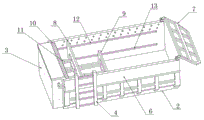
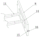
In the figure: 1. a vehicle body; 2. a carriage; 3. a water storage tank; 4. hanging a barrel rack; 5. a top cover; 6. a protective box; 7. a rear box door; 8. a push plate is arranged; 9. a lower push plate; 10. a storage box; 11. a hydraulic push rod; 12. an upper slide rail; 13. a lower slide rail; 14. a connecting seat; 15. a slide base; 16. a scraper knife; 17. a water spray hole; 18. a chute; 19. a limiting seat; 20. an electric push rod; 21. a lower nozzle; 22. an upper spray head; 23. a hydraulic cylinder; 61. a lower pipeline; 62. an upper pipeline; 63. a baffle plate; 64. a water drainage groove.
Detailed Description
The technical solutions in the embodiments of the present invention will be clearly and completely described below with reference to the drawings in the embodiments of the present invention, and it is obvious that the described embodiments are only a part of the embodiments of the present invention, and not all of the embodiments. All other embodiments, which can be derived by a person skilled in the art from the embodiments given herein without making any creative effort, shall fall within the protection scope of the present invention.
Referring to fig. 1 to 5, in the embodiment of the invention, an electric sanitation bucket hanging vehicle with a garbage pushing and compressing mechanism comprises a vehicle body 1, a carriage 2 is connected to the rear side of the vehicle body 1, a water storage tank 3 is arranged at the front end of the carriage 2, flushing mechanisms are arranged on two side faces of the carriage 2, the pushing and compressing mechanism and a discharging mechanism are arranged inside the carriage 2, a top cover 5 is arranged at the top end of the carriage 2, a rear box door 7 is connected to the rear side face of the carriage 2, a bucket hanging frame 4 is arranged on the side face of the front end of the carriage 2, a hydraulic cylinder 23 is arranged at the connection position of the middle part of the lower surface of the carriage 2 and the vehicle body 1, water spraying holes 17 are correspondingly formed in the upper end of the inner side wall of the carriage 2, the water.
The pushing and compressing mechanism comprises a containing box 10 positioned at the front end inside the carriage 2, a hydraulic push rod 11 extends inside the containing box 10, one end of the hydraulic push rod 11 is connected with an upper push plate 8, two side faces, corresponding to the upper push plate 8, of the inner side wall of the carriage 2 are provided with upper slide rails 12, the pushing and compressing mechanism also comprises slide seats 15 positioned at two side faces, corresponding to the upper slide rails 12, of the upper push plate 8, one side face of each slide seat 15 is connected with a scraper 16, each scraper 16 is of a triangular stainless steel structure, a connecting seat 14 is arranged at the joint of the upper push plate 8 and the hydraulic push rod 11, the upper push plate 8 and the hydraulic push rod 11 are fixedly connected through the connecting seat 14, two side faces of the upper push plate 8 are slidably connected with the inner side wall of the carriage 2 through the upper slide rails 12 and the slide seats 15, and when the garbage can is poured into the, due to the influence of the position of the barrel hanging frame 4, the garbage poured into the carriage 2 from the garbage can is in the same position, then the garbage at the position corresponding to the barrel hanging rack 4 in the carriage 2 is accumulated after being dumped for a plurality of times, at the moment, the upper push plate 8 is driven to push by controlling the extension and contraction of the hydraulic push rod 11 at the upper part, so that the garbage accumulated in the carriage 2 can be pushed to the rear part of the carriage 2, so that the garbage can be uniformly stored in the carriage 2, and when the push-up plate 8 moves to the rear side in the carriage 2, because rubbish becomes many, have partial rubbish to enter into last slide rail 12 in, at this moment, utilize the spiller 16 of slide 15 one side to carry out the shovel to removing in going up slide rail 12, keep unobstructed in the messenger goes up slide rail 12, the push up board 8 of being convenient for is to the promotion compression of piling up rubbish, both makes things convenient for storage rubbish that carriage 2 can be more, also makes things convenient for the concertina movement of push up board 8, has solved 2 interior rubbish of traditional carriage and has piled up the problem of unable reasonable application carriage 2 inner space area.
The discharging mechanism comprises a lower push plate 9 positioned at the lower end of an upper push plate 8, the lower push plate 9 and the upper push plate 8 are the same in size, lower sliding rails 13 are arranged on the inner side wall of the carriage 2 corresponding to two side faces of the lower push plate 9, the lower push plate 9 and the upper push plate 8 are the same in structural size, the sum of the heights of the lower push plate 9 and the upper push plate 8 is slightly smaller than the height of the inside of the carriage 2, two hydraulic push rods 11 are arranged in two groups, one end of each hydraulic push rod 11 is fixed inside a containing box 10, the other end of each hydraulic push rod 11 penetrates through the containing box 10 and is respectively and vertically connected with the upper push plate 8 and the lower push plate 9, when the discharging mechanism works, the carriage 2 is jacked up through a control hydraulic cylinder 23, a rear box door 7 is opened, garbage in the carriage 2 is poured out through the rear side, but, will cause the inside rubbish that glues in carriage 2 or produce dense smell, consequently the during operation drives down push pedal 9 through the hydraulic pressure push rod 11 of control lower part and stretches out and draws back, utilizes push pedal 9 to release the rubbish of carriage 2 bottom to can thoroughly dump its inside rubbish when carriage 2 dumps rubbish, improve carriage 2's the efficiency of unloading, the theory of operation of push pedal 9 is unanimous with the theory of operation of push pedal 8 down.
The washing mechanism comprises a protective box 6 positioned at the upper ends of two outer side surfaces of a carriage 2, a lower pipeline 61 is arranged in the protective box 6, an upper pipeline 62 is arranged on one side of the lower pipeline 61, a baffle 63 is arranged in the protective box 6 and close to the outer side wall of the carriage 2, a drainage groove 64 is arranged at the bottom end of the inner part of the protective box 6 and close to the outer side wall of the carriage 2, a lower spray head 21 positioned at the inner side of the lower pipeline 61 and corresponding to a lower row of spray holes 17, an upper spray head 22 is arranged at the position of the inner side of the upper pipeline 62 and corresponding to the upper row of spray holes 17, supports are arranged on the surfaces of the lower pipeline 61 and the upper pipeline 62, the lower pipeline 61 and the upper pipeline 62 are connected with the bottom of the protective box 6 through the supports, the number of the lower spray heads 21 is the same as and corresponding to the number of the lower row of spray holes 17, the spraying direction of the upper spray head 22 is downward, the lower end of the baffle 63 is provided with at least three electric push rods 20, the number of the baffle 63 is two, the two baffles 63 are same in size and respectively correspond to the two rows of drain holes 17, the distance between the two baffles 63 is just the same as the width of one of the baffles 63, the rear side of each baffle 63 is provided with at least three limiting seats 19 at equal intervals, one side of the outer side surface of the carriage 2, which is close to the water spraying holes 17, is provided with a sliding groove 18 corresponding to the limiting seats 19, the baffle 63 is fixedly connected with the bottom of the protective box 6 through the electric push rods 20, the side surface of the baffle 63 is in sliding connection with the outer side of the carriage 2 through the sliding groove 18 and the limiting seats 19, the baffle 63 is a stainless steel plate with the thickness of about 3 centimeters, after garbage in the carriage 2 is dumped, the electric push rods 20 are controlled to stretch, the baffle 63, through the work of the high pressure water pump in the control storage water tank 3 again, and then the cooperation pipeline is with the water suction in the storage water tank 3 go up pipeline 62 and lower pipeline 61 in, and spout through last shower nozzle 22 and lower shower nozzle 21, at this moment, it just corresponds last hole for water spraying 17 to go up shower nozzle 22, lower shower nozzle 21 just corresponds hole for water spraying 17 down, and then it can carry out high-pressure water spray in to carriage 2 through hole for water spraying 17 with lower shower nozzle 21 to go up shower nozzle 22, and because of the restriction of last shower nozzle 22 and lower shower nozzle 21 play water direction, can utilize last shower nozzle 22 to wash the lower extreme of 2 inside walls in carriage, utilize lower shower nozzle 21 to wash the inside wall upper end in carriage 2, thereby realize crisscross washing, can carry out high pressure to the inner wall in carriage 2 comprehensively and wash, further improvement the inside cleanliness factor in carriage 2, annotate: when the carriage 2 stores garbage, part of the garbage may enter the water spraying holes 17, but the garbage is not blocked under the action of the high-pressure nozzle, and in addition, after the garbage is washed, the electric push rod 20 is controlled to push the baffle 63 to move upwards, so that the two rows of the water spraying holes 17 are just blocked by the two baffles 63, and the garbage is prevented from entering the protective box 6 through the water spraying holes 17.
One end of water drainage tank 64 is connected with the drain pipe, and the one end of drain pipe extends to the inside of storage water tank 3, the inside of storage water tank 3 is provided with high pressure water pump, and high pressure water pump's output is linked together with the one end of lower pipeline 61 and upper pipeline 62 respectively through the trunk line, because of there being the clearance (clearance width slightly is greater than the thickness of baffle 63 promptly) between shower nozzle and the hole for water spraying 17, and then when the water spray begins or finishes, there is water to fall into protective housing 6, and then can collect the water that flows down through water drainage tank 64, and in draining into storage water tank 3 through the drain pipe, and then ensured the cleanness in protective housing 6, the waste of wasing water has also been avoided simultaneously.
The working principle of the invention is as follows: when the garbage in the garbage can is collected, the garbage can is influenced by the position of the garbage hanging frame 4 when the garbage in the garbage can is poured into the carriage 2 through the garbage hanging frame 4 matched with the existing garbage turning equipment, the garbage poured into the carriage 2 in the garbage can is at the same position, and then after being poured for many times, the garbage at the position corresponding to the garbage hanging frame 4 in the carriage 2 can be accumulated, at the moment, the upper push plate 8 is driven to push through the telescopic driving of the hydraulic push rod 11 at the upper part, so that the garbage accumulated in the carriage 2 can be pushed to the rear part of the carriage 2, the garbage can be uniformly stored in the carriage 2, the reasonable utilization of the internal space of the carriage 2 is facilitated, and the problem that the garbage accumulated in the conventional carriage 2 cannot reasonably utilize the internal space area of the carriage 2 is solved;
when dumping garbage in the carriage 2, the carriage 2 is jacked up by controlling the hydraulic cylinder 23, the rear box door 7 is opened, and the garbage in the carriage 2 is dumped through the rear side, but because moisture and sundries exist in the garbage, the garbage cannot be dumped completely when dumped, the lower hydraulic push rod 11 is controlled to drive the lower push plate 9 to stretch and retract, and the garbage at the bottom of the carriage 2 is pushed out by utilizing the lower push plate 9, so that the garbage in the carriage 2 can be dumped thoroughly when the carriage 2 dumps the garbage, and the unloading efficiency of the carriage 2 is improved;
after unloading is finished, the carriage 2 is restored, the electric push rod 20 is controlled to stretch and retract, the baffle 63 in the protective box 6 moves downwards along the sliding groove 18, the water spraying holes 17 are exposed, the high-pressure water pump in the water storage tank 3 is controlled to work, water in the water storage tank 3 is pumped into the upper pipeline 62 and the lower pipeline 61 by matching with the pipelines and is sprayed out through the upper spray head 22 and the lower spray head 21, the upper spray head 22 and the lower spray head 21 spray water into the carriage 2 at high pressure through the water spraying holes 17, and the upper end and the lower end of the inner side wall of the carriage 2 can be comprehensively washed due to the limitation of the water outlet directions of the upper spray head 22 and the lower spray head 21, so that the cleanness inside the carriage 2 is further improved;
the design is simple and convenient to operate, the utilization rate of the inner space of the carriage 2 is improved, the loading and unloading efficiency is improved, the interior of the carriage 2 can be thoroughly washed by matching with the use of the washing mechanism, the cleanness of the interior of the carriage 2 is improved, and the internal environmental sanitation is improved.
It should be noted that: the electric push rod 20 is ANT-52, the hydraulic push rod 11 is of DYTZ series, the specific stroke is selected according to the length inside the carriage, and the high-pressure water pump is of WQX6 series small high-pressure water pump.
It will be evident to those skilled in the art that the invention is not limited to the details of the foregoing illustrative embodiments, and that the present invention may be embodied in other specific forms without departing from the spirit or essential attributes thereof. The present embodiments are therefore to be considered in all respects as illustrative and not restrictive, the scope of the invention being indicated by the appended claims rather than by the foregoing description, and all changes which come within the meaning and range of equivalency of the claims are therefore intended to be embraced therein. Any reference sign in a claim should not be construed as limiting the claim concerned.
Claims (9)
1. An electric sanitation bucket hanging vehicle with a garbage pushing and compressing mechanism comprises a vehicle body (1) and is characterized in that the rear side of the vehicle body (1) is connected with a carriage (2), a water storage tank (3) is arranged at the front end of the carriage (2), flushing mechanisms are arranged on two side faces of the carriage (2), and the garbage pushing and compressing mechanism and a discharging mechanism are arranged inside the carriage (2);
the pushing and compressing mechanism comprises a containing box (10) positioned at the front end inside the carriage (2), a hydraulic push rod (11) extends inside the containing box (10), one end of the hydraulic push rod (11) is connected with an upper push plate (8), and upper sliding rails (12) are arranged on the inner side wall of the carriage (2) and correspond to the two side surfaces of the upper push plate (8);
the discharging mechanism comprises a lower push plate (9) positioned at the lower end of the upper push plate (8), the lower push plate (9) and the upper push plate (8) are the same in size, and lower sliding rails (13) are arranged on the inner side wall of the carriage (2) corresponding to two side faces of the lower push plate (9);
the flushing mechanism comprises a protective box (6) located at the upper end of two outer side faces of a carriage (2), a lower pipeline (61) is arranged inside the protective box (6), an upper pipeline (62) is arranged on one side of the lower pipeline (61), a baffle (63) is arranged on the outer side wall, close to the carriage (2), of the inside of the protective box (6), and a drainage groove (64) is formed in the outer side wall, close to the carriage (2), of the bottom end of the inside of the protective box (6).
2. The electric sanitation bucket hanging vehicle with the garbage pushing and compressing mechanism is characterized in that a top cover (5) is arranged at the top end of the carriage (2), a rear box door (7) is connected to the rear side face of the carriage (2), a bucket hanging frame (4) is arranged on the front side face of the carriage (2), a hydraulic cylinder (23) is arranged at the joint of the middle of the lower surface of the carriage (2) and the vehicle body (1), water spraying holes (17) are correspondingly formed in the upper end of the inner side wall of the carriage (2), the water spraying holes (17) are divided into an upper row and a lower row, and the positions of the water spraying holes (17) in the upper row and the lower row are not in the same vertical direction.
3. The electric sanitation hanging barrel vehicle with the garbage pushing and compressing mechanism is characterized in that the garbage pushing and compressing mechanism further comprises sliding seats (15) which are positioned on two side surfaces of the upper pushing plate (8) and correspond to the upper sliding rails (12), a scraper knife (16) is connected to one side surface of each sliding seat (15), each scraper knife (16) is of a triangular stainless steel structure, a connecting seat (14) is arranged at the joint of the upper pushing plate (8) and the hydraulic push rod (11), and the upper pushing plate (8) is fixedly connected with the hydraulic push rod (11) through the connecting seat (14).
4. The electric sanitation hanging barrel vehicle with a garbage pushing and compressing mechanism is characterized in that the lower push plate (9) and the upper push plate (8) are the same in structural size, the sum of the heights of the lower push plate (9) and the upper push plate (8) is slightly smaller than the height of the interior of the carriage (2), the hydraulic push rods (11) are arranged in two groups, two in each group, one end of each hydraulic push rod (11) is fixed in the interior of the containing box (10), and the other end of each hydraulic push rod (11) penetrates through the containing box (10) and is vertically connected with the upper push plate (8) and the lower push plate (9) respectively.
5. The electric sanitation hanging barrel vehicle with a garbage pushing and compressing mechanism is characterized in that the flushing mechanism further comprises a lower nozzle (21) which is positioned on the inner side of the lower pipeline (61) and corresponds to the lower row of the water spraying holes (17), an upper nozzle (22) is arranged on the inner side of the upper pipeline (62) and corresponds to the upper row of the water spraying holes (17), a bracket is arranged on the surface of each of the lower pipeline (61) and the upper pipeline (62), and the lower pipeline (61) and the upper pipeline (62) are connected with the bottom of the protective box (6) through the bracket.
6. The electric sanitation hanging barrel vehicle with a garbage pushing and compressing mechanism is characterized in that the number of the lower spray heads (21) is the same as and corresponds to the number of the lower rows of the water spraying holes (17), the number of the upper spray heads (22) is the same as and corresponds to the number of the upper rows of the water spraying holes (17), the spraying direction of the lower spray heads (21) is upward, and the spraying direction of the upper spray heads (22) is downward.
7. The electric sanitation hanging bucket vehicle with a garbage pushing and compressing mechanism is characterized in that one end of the drainage groove (64) is connected with a drainage pipe, one end of the drainage pipe extends to the inside of the water storage tank (3), a high-pressure water pump is arranged inside the water storage tank (3), and the output end of the high-pressure water pump is respectively communicated with one end of the lower pipeline (61) and one end of the upper pipeline (62) through a main pipeline.
8. The electric sanitation hanging barrel vehicle with a garbage pushing and compressing mechanism is characterized in that at least three electric push rods (20) are arranged at the lower ends of the baffle plates (63), two baffle plates (63) are arranged, the two baffle plates (63) are the same in size and correspond to the two rows (17), the distance between the two baffle plates (63) is just the same as the width of one baffle plate (63), at least three limiting seats (19) are arranged on the rear sides of the baffle plates (63) at equal intervals, and a sliding groove (18) is formed in one side, close to a water spraying hole (17), of the carriage (2) and corresponds to the position of the limiting seat (19).
9. The electric sanitation hanging barrel vehicle with a garbage pushing and compressing mechanism is characterized in that the baffle (63) is fixedly connected with the bottom of the protective box (6) through an electric push rod (20), the side surface of the baffle (63) is slidably connected with the outer side of the carriage (2) through a chute (18) and a limiting seat (19), and the baffle (63) is a stainless steel plate with the thickness of about 3 centimeters.
Priority Applications (1)
| Application Number | Priority Date | Filing Date | Title |
|---|---|---|---|
| CN202010153871.2A CN111169874A (en) | 2020-03-07 | 2020-03-07 | Electric sanitation bucket hanging vehicle with garbage pushing and compressing mechanism |
Applications Claiming Priority (1)
| Application Number | Priority Date | Filing Date | Title |
|---|---|---|---|
| CN202010153871.2A CN111169874A (en) | 2020-03-07 | 2020-03-07 | Electric sanitation bucket hanging vehicle with garbage pushing and compressing mechanism |
Publications (1)
| Publication Number | Publication Date |
|---|---|
| CN111169874A true CN111169874A (en) | 2020-05-19 |
Family
ID=70625188
Family Applications (1)
| Application Number | Title | Priority Date | Filing Date |
|---|---|---|---|
| CN202010153871.2A Pending CN111169874A (en) | 2020-03-07 | 2020-03-07 | Electric sanitation bucket hanging vehicle with garbage pushing and compressing mechanism |
Country Status (1)
| Country | Link |
|---|---|
| CN (1) | CN111169874A (en) |
Cited By (14)
| Publication number | Priority date | Publication date | Assignee | Title |
|---|---|---|---|---|
| CN112357422A (en) * | 2020-09-23 | 2021-02-12 | 安徽皖丰车业有限公司 | Self-loading and unloading bucket-hanging type garbage truck |
| CN112551008A (en) * | 2020-11-14 | 2021-03-26 | 徐州易尔环保科技有限公司 | Sanitation garbage truck with clean function |
| CN112707068A (en) * | 2020-12-17 | 2021-04-27 | 合肥佳华环境工程科技有限公司 | Compression type garbage transport vehicle |
| CN113022409A (en) * | 2021-04-16 | 2021-06-25 | 湖南路港建设有限公司 | Carriage for dump truck for digital earth excavation construction |
| CN113199975A (en) * | 2021-06-12 | 2021-08-03 | 河南跃薪智能机械有限公司 | Ore auxiliary unloading equipment on mining dump truck |
| CN113427814A (en) * | 2021-06-08 | 2021-09-24 | 厦门策琥贸易有限公司 | Automatic discharging device for kitchen waste treatment |
| CN113859825A (en) * | 2021-09-26 | 2021-12-31 | 徐州德高电动车科技有限公司 | Hanging type electric garbage transport vehicle |
| CN114111977A (en) * | 2020-08-27 | 2022-03-01 | 中石化石油工程技术服务有限公司 | Device and method for intelligently controlling pipeline steel wire brush to clean and weigh rock debris on tray |
| CN114453389A (en) * | 2021-12-31 | 2022-05-10 | 长沙中联重科环境产业有限公司 | Novel material crushing car |
| CN114622845A (en) * | 2020-12-11 | 2022-06-14 | 中石化石油工程技术服务有限公司 | Device and method for intelligently controlling and removing rock debris on weighing tray |
| CN114635384A (en) * | 2022-04-15 | 2022-06-17 | 陕西黑松环保科技有限公司 | High intelligent full-automatic formula cleans garbage truck |
| CN115215020A (en) * | 2022-07-21 | 2022-10-21 | 扬州福达兰特环保机械有限公司 | No-leakage back-feeding electric three-wheel compression collecting vehicle |
| CN115285553A (en) * | 2022-08-04 | 2022-11-04 | 扬州源友环保科技有限公司 | Sealed effectual rubbish transfer car (buggy) |
| CN115924363A (en) * | 2023-03-15 | 2023-04-07 | 黎明职业大学 | Efficient and environment-friendly garbage truck and using method thereof |
Citations (5)
| Publication number | Priority date | Publication date | Assignee | Title |
|---|---|---|---|---|
| JPS54144067A (en) * | 1978-04-28 | 1979-11-09 | Shin Meiwa Ind Co Ltd | Compactor/container |
| CN105292873A (en) * | 2015-12-11 | 2016-02-03 | 苏州市启扬商贸有限公司 | Multi-push-plate pushing and extruding type electric sanitation tricycle |
| CN109592268A (en) * | 2019-01-04 | 2019-04-09 | 甘肃兴华环境设施有限公司 | A kind of Full sealed garbage collection vehicle |
| CN110255018A (en) * | 2019-08-06 | 2019-09-20 | 江苏奥新新能源汽车有限公司 | A kind of electric dust cart rubbish automatic compression apparatus |
| CN110789886A (en) * | 2019-11-14 | 2020-02-14 | 安徽兴邦专用汽车股份有限公司 | Garbage truck with self-cleaning function |
-
2020
- 2020-03-07 CN CN202010153871.2A patent/CN111169874A/en active Pending
Patent Citations (5)
| Publication number | Priority date | Publication date | Assignee | Title |
|---|---|---|---|---|
| JPS54144067A (en) * | 1978-04-28 | 1979-11-09 | Shin Meiwa Ind Co Ltd | Compactor/container |
| CN105292873A (en) * | 2015-12-11 | 2016-02-03 | 苏州市启扬商贸有限公司 | Multi-push-plate pushing and extruding type electric sanitation tricycle |
| CN109592268A (en) * | 2019-01-04 | 2019-04-09 | 甘肃兴华环境设施有限公司 | A kind of Full sealed garbage collection vehicle |
| CN110255018A (en) * | 2019-08-06 | 2019-09-20 | 江苏奥新新能源汽车有限公司 | A kind of electric dust cart rubbish automatic compression apparatus |
| CN110789886A (en) * | 2019-11-14 | 2020-02-14 | 安徽兴邦专用汽车股份有限公司 | Garbage truck with self-cleaning function |
Cited By (18)
| Publication number | Priority date | Publication date | Assignee | Title |
|---|---|---|---|---|
| CN114111977A (en) * | 2020-08-27 | 2022-03-01 | 中石化石油工程技术服务有限公司 | Device and method for intelligently controlling pipeline steel wire brush to clean and weigh rock debris on tray |
| CN112357422A (en) * | 2020-09-23 | 2021-02-12 | 安徽皖丰车业有限公司 | Self-loading and unloading bucket-hanging type garbage truck |
| CN112551008A (en) * | 2020-11-14 | 2021-03-26 | 徐州易尔环保科技有限公司 | Sanitation garbage truck with clean function |
| CN114622845A (en) * | 2020-12-11 | 2022-06-14 | 中石化石油工程技术服务有限公司 | Device and method for intelligently controlling and removing rock debris on weighing tray |
| CN114622845B (en) * | 2020-12-11 | 2024-03-26 | 中石化石油工程技术服务股份有限公司 | Device and method for intelligently controlling and removing rock debris of weighing tray |
| CN112707068A (en) * | 2020-12-17 | 2021-04-27 | 合肥佳华环境工程科技有限公司 | Compression type garbage transport vehicle |
| CN113022409A (en) * | 2021-04-16 | 2021-06-25 | 湖南路港建设有限公司 | Carriage for dump truck for digital earth excavation construction |
| CN113427814B (en) * | 2021-06-08 | 2022-11-11 | 嘉兴传盛机械设备有限公司 | Automatic discharging device for kitchen waste treatment |
| CN113427814A (en) * | 2021-06-08 | 2021-09-24 | 厦门策琥贸易有限公司 | Automatic discharging device for kitchen waste treatment |
| CN113199975A (en) * | 2021-06-12 | 2021-08-03 | 河南跃薪智能机械有限公司 | Ore auxiliary unloading equipment on mining dump truck |
| CN113199975B (en) * | 2021-06-12 | 2022-05-20 | 河南跃薪智能机械有限公司 | Ore auxiliary unloading equipment on mining dump truck |
| CN113859825A (en) * | 2021-09-26 | 2021-12-31 | 徐州德高电动车科技有限公司 | Hanging type electric garbage transport vehicle |
| CN114453389A (en) * | 2021-12-31 | 2022-05-10 | 长沙中联重科环境产业有限公司 | Novel material crushing car |
| CN114635384A (en) * | 2022-04-15 | 2022-06-17 | 陕西黑松环保科技有限公司 | High intelligent full-automatic formula cleans garbage truck |
| CN115215020A (en) * | 2022-07-21 | 2022-10-21 | 扬州福达兰特环保机械有限公司 | No-leakage back-feeding electric three-wheel compression collecting vehicle |
| CN115285553A (en) * | 2022-08-04 | 2022-11-04 | 扬州源友环保科技有限公司 | Sealed effectual rubbish transfer car (buggy) |
| CN115924363A (en) * | 2023-03-15 | 2023-04-07 | 黎明职业大学 | Efficient and environment-friendly garbage truck and using method thereof |
| CN115924363B (en) * | 2023-03-15 | 2023-05-02 | 黎明职业大学 | Efficient and environment-friendly garbage truck and application method thereof |
Similar Documents
| Publication | Publication Date | Title |
|---|---|---|
| CN111169874A (en) | Electric sanitation bucket hanging vehicle with garbage pushing and compressing mechanism | |
| CN108820656A (en) | A kind of municipal garbage vehicle facilitating internal cleaning | |
| CN205708363U (en) | Dumper | |
| CN209038336U (en) | On-board high-voltage cleaning system with dustbin cleaning function | |
| CN211469551U (en) | Compressing device for cleaning urban garbage | |
| CN103144343A (en) | Vertical quantitative pre-compaction large trash compactor | |
| CN113002043B (en) | Garbage compression classification recycling device | |
| CN111980912B (en) | Portable wisdom pump station | |
| CN203306545U (en) | Kitchen garbage truck | |
| CN112046444A (en) | Car wash platform that building site used | |
| CN217147246U (en) | High-efficient rubbish collection fortune car | |
| CN215157947U (en) | Garbage compression equipment | |
| CN212048934U (en) | Garbage collecting and releasing device with self-cleaning function | |
| CN211200228U (en) | Sweeper with sweeping device replaced according to types of garbage in sweeping field | |
| CN213610001U (en) | Filtering device for polyester production wastewater | |
| CN211359951U (en) | Environment-friendly dumper | |
| CN109629803B (en) | Wall plastering machine capable of automatically recovering scattered mortar | |
| CN112211275A (en) | Automatic dredging, cleaning and collecting device for sewer opening | |
| CN113856298A (en) | Villages and small towns is liftable grid for sewage treatment | |
| CN218369794U (en) | High-pressure flushing device for garbage pavilion | |
| CN218574402U (en) | Cleaning device for garbage lifting platform | |
| CN218911595U (en) | A rainwater collection device for among scenery gardens | |
| CN112813894A (en) | Sweeper with sweeping device replaced according to types of garbage in sweeping field | |
| CN216108911U (en) | Automatic water changing vehicle cleaning pool for building construction | |
| CN213477130U (en) | Automatic dredging, cleaning and collecting device for sewer opening |
Legal Events
| Date | Code | Title | Description |
|---|---|---|---|
| PB01 | Publication | ||
| PB01 | Publication | ||
| SE01 | Entry into force of request for substantive examination | ||
| SE01 | Entry into force of request for substantive examination | ||
| RJ01 | Rejection of invention patent application after publication |
Application publication date: 20200519 |
|
| RJ01 | Rejection of invention patent application after publication |